Messerschmidt U. Dislocation Dynamics During Plastic Deformation
Подождите немного. Документ загружается.

422 10 Quasicrystals
1
2
3
4
2
3
4
PP
SP
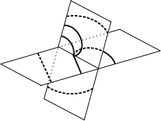
Fig. 10.24. Schematic of the multiplication of dislocations in Al–Pd–Mn after a
change from the primary plane of motion PP onto a secondary one SP. After [711]
different planes. After full bow-out, two dislocations move on the secondary
plane in opposite directions (stage 4). Thus, dislocation motion spreads from
one plane onto other planes as discussed in connection with Fig. 10.18, lead-
ing to the dislocation networks formed at high temperatures. However, at low
temperatures, the dislocations seem to return to planes parallel to the origi-
nal ones similar to the multiplication in crystals as indicated by the narrow
dislocation bands observed (Fig. 10.15b).
The following video clip illustrates dislocation generation, always con-
nected with some change of the plane of motion.
Video 10.5. Dislocation multiplication in i-Al–Pd–Mn single quasicrystals: The
three sequences were taken at 720, 685, and 675
◦
C. The parent dislocations are
marked by M. In the first sequence, the dislocation changes its plane of motion to
a new one as described above. Two new dislocations emerge and move in oppo-
site directions on a plane with its trace perpendicular to the tensile direction. In the
second sequence, the multiplication event is connected with a small parallel displace-
ment of the plane of motion. One dislocation quickly moves backwards, followed by
two dislocations moving in forward direction. In the third sequence, the dislocation
undergoes a shift onto a parallel plane. At A, one dislocation moving back annihi-
lates with another one on the same plane. At R, two dislocations moving on planes
with parallel traces of different inclination in the foil react with each other. As a
result, a dislocation with double contrast moves to the right.
The in situ study in [704] also revealed dislocation multiplication.
10.3.2 d-Al–Ni–Co
As classified in [716,717], the decagonal phase of Al–Ni–Co may have different
modifications depending on the exact composition. In the electron diffraction
patterns, they show particular superstructure reflections, being first observed
in [718]. The different modifications correspond to different states of structural
and chemical order. At the Co and Ni-rich ends of the decagonal phase field,
the decagonal structures do not show superlattice reflections. These structures
are termed ‘basic Co-rich’ and ‘basic Ni-rich’ variants. The results following
below are confined to the composition Al-15at%Ni-15at%Co with the type I
superstructure showing the so-called S1 and S2 superlattice reflections [718].
10.3 Microscopic Observations of Dislocations 423
2
3
4
5
6
b
2
b
3
b
4
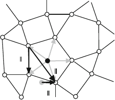
Fig. 10.25. Parallel components of the Burgers vectors in d-Al–Ni–Co single qua-
sicrystals as determined in [720]. b
1
is directed perpendicular to the quasiperiodic
image plane
The Burgers vectors of dislocations in decagonal quasicrystals were first
studied by Zhang and Urban [719] via contrast extinction, and later on by
other authors also by applying the CBED method (e.g., [719,720]). The paral-
lel components of the observed Burgers vectors are outlined in Fig. 10.25. The
grey arrows marked by 2 to 6 are the basis vectors in the quasicrystalline plane.
They are longer by a factor of τ than those introduced by Steurer et al. [667].
The Burgers vectors observed are the following: the periodic Burgers vector
directed along the periodic axis of the length of the c lattice constant in par-
allel space, in the full five-dimensional notation of Steurer et al. [667] written
as B
1
= [00001], the Burgers vectors in the quasiperiodic plane B
2
=[
¯
10010]
and B
3
=[
¯
1
¯
1010] of the lengths of 0.29 nm and 0.47 nm in parallel space,
and a mixed Burgers vector B
4
=[
¯
1/5,
¯
1/5,
¯
1/5,
¯
1/5,
¯
1/2] of the length of
0.25 nm in parallel space. The mixed Burgers vector is not a lattice vector
in hyperspace so that the respective dislocations are partial dislocations. The
strain accommodation parameters ζ for the quasiperiodic Burgers vectors are
τ
−1
and τ
−3
. Compared to i-Al–Pd–Mn, in d-Al–Ni–Co these values indicate
a lower tendency of the dislocations to be accompanied with phason defects.
The dislocations induced by plastic deformation show very strong preferen-
tial orientations parallel or perpendicular to the periodic axis. The dislocations
with periodic Burgers vectors assume both these line directions whereas those
with quasiperiodic or mixed Burgers vectors are arranged only parallel to the
periodic axis.
While, because of the high symmetry of icosahedral Al–Pd–Mn, its plastic
behavior is very isotropic, decagonal Al–Ni–Co has a restricted number of
Burgers vectors of different character and only a few dislocation line directions
resulting in a remarkable plastic anisotropy. It was first revealed on single Al–
Ni–Co quasicrystals in [721]. Mostly, stress–strain curves were measured with
loading axes parallel to the periodic axis, perpendicular to it, and at an angle
of 45
◦
, which may be denoted A
, A
⊥
,andA
45
. The highest yield stress always
has the orientation A
⊥
, whereas the lowest one has A
45
. The amount of the
intermediate value of A
depends on the composition, it is slightly higher than
424 10 Quasicrystals
that of A
45
for Al-15at%Ni-15at%Co and slightly less than that of A
⊥
for the
basic Co-rich material.
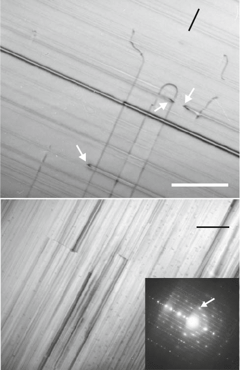
A characteristic deformation microstructure produced during in situ defor-
mation along the A
axis is shown in Fig. 10.26a. The figure was taken with a
systematic row of reflections parallel to the periodic axis, i.e., containing the
G = (00002) reflection, with a higher reflection excited (high-order bright-field
technique). This direction is also the tensile direction TD. Under these con-
ditions, dislocations with quasiperiodic Burgers vectors are extinguished. The
arrows in the figure point to dislocations with a periodic Burgers vector, which
appear as short dark lines that are attached to extended gray lines, which are
the traces of the dislocation motion. The periodic dislocations, which are seen
almost end-on, move along quasiperiodic planes perpendicular to the periodic
axis. Many other traces in the same direction as of dislocations running out
of the image area are visible as well. The dark double line in the center of the
figure is the trace of many dislocations. The gray lines parallel to the tensile
direction, marked by M, are dislocations which, according to [720], have mixed
Burgers vectors.
Figure 10.26b refers to a different specimen region, taken with a system-
atic row containing the quasiperiodic reflection G =(
¯
10010). Dislocations
with mixed and quasiperiodic Burgers vectors are visible but those with the
periodic Burgers vector are now extinguished. The entire image shows a back-
ground structure with a striation contrast parallel to the tenfold axis. This
contrast possibly originates from phason boundaries resulting from phason
disorder [722]. It appears under all diffraction vectors that exhibit any com-
ponent in the quasiperiodic direction. It makes the observation of dislocations
difficult.
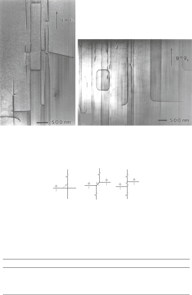
In macroscopic deformation experiments, all specimens were deformed
within the high-temperature range. In the A
orientation, the dislocations
form networks between dislocations with periodic and mixed Burgers vectors
as illustrated in Fig. 10.27a. Similar structures are observed in Al-15at%Ni-
15at%Co. Burgers vector analysis by the CBED method [720] showed that the
networks are formed by dislocation reactions with the periodic component of
the Burgers vector of the mixed dislocation being opposite to the direction
of the Burgers vector of the periodic dislocations, as outlined in Fig. 10.28.
The dislocations in Fig. 10.28a move across each other, forming a junction in
(b). The reaction is connected with a gain in energy. In (c), the junction has
rearranged. According to the definition in Sect. 10.3.1, the dislocations with
periodic Burgers vectors running horizontally in Fig. 10.27a are equivalent to
set A experiencing a high climb force but no glide force.
In the A
45
orientation, periodic dislocations arrange along the screw and
edge orientations with the screws dominating as illustrated in Fig. 10.27b.
The image plane is parallel to planes marked by slip steps on the specimen
surface. The figure also shows a dislocation loop. If it is assumed that the
loop plane is also the plane of motion, the loop has been formed by glide.
It may therefore be concluded that periodic dislocations in d-Al–Ni–Co can
10.3 Microscopic Observations of Dislocations 425
1 µm
M
M
M
C
TD
(a)
1µm
(00004)
(b)
Fig. 10.26. Deformation microstructure during in situ straining of a d-Al–15at%Ni–
15at%Co single quasicrystal along the A
axis in an HVEM at 730
◦
C, taken at the
P2 twofold pole of the foil normal. (a) g vector in the direction of the periodic axis.
(b)Quasiperiodicg vector. From [666]. Copyright Mater. Res. Soc. (2005)
glide. In addition, also dislocations with mixed Burgers vectors contribute to
the deformation. At the A
⊥
deformation axis, dislocations with quasiperiodic
and mixed Burgers vectors dominate. They are arranged along the periodic
axis.
Some dislocation density data of deformed Al–Ni–Co single quasicrystals
are compiled in Table 10.1, revealing a slight dominance of periodic disloca-
tions in the A
45
orientation, where slip of periodic dislocations is possible,
with a comparatively very low value of the total dislocation density. All
426 10 Quasicrystals
(a)
(b)
Fig. 10.27. Dislocation structures in decagonal basic Co-rich Al–Ni–Co single qua-
sicrystals deformed in macroscopic compression. (a) A
compression axis, 890
◦
C,
image plane containing the tenfold g vector g
p
.(b) A
45
compression axis, 790
◦
C,
image plane parallel to slip plane. g vector parallel to tenfold direction. From [723],
courtesy of Peter Schall
(a) (b) (c)
Fig. 10.28. Schematic of the reaction after [720, 723] between dislocations with
periodic and mixed Burgers vectors in d-Al–Ni–Co to form a dislocation network.
The Burgers vectors are indicated by grey arrows
Table 10.1. Densities of dislocations with periodic
p
,mixed
m
, and quasiperiodic
Burgers vectors
qp
in deformed Al–Ni–Co single quasicrystals in units of 10
12
m
−2
.
ps
and
pe
are densities of periodic screw and edge dislocations. Data from [723]
material, axis T (
◦
C) ε (%)
p
ps
pe
m
qp
Basic Co, A
860 6 4.2 14.5
Basic Co, A
45
860 6 0.6 0.2 0.5
Al-15Ni-15Co, A
45
790 4.50.10.60.6
Basic Co, A
⊥
860 6 1.2 17 19
10.3 Microscopic Observations of Dislocations 427
dislocation densities are remarkably higher than those in undeformed but
annealed reference specimens. They decrease with increasing temperature.
In situ straining experiments in an HVEM [666] yielded some character-
istics of dislocation motion in the A
orientation at 730
◦
C. This temperature
is relatively low compared with the temperatures of the conventional TEM
experiments described above. Most dislocations observed moved on planes per-
pendicular to the periodic axis, like those indicated by arrows in Fig. 10.26a.
These dislocations consist of two straight segments with a sharp knee between
them. They move by pure climb since their Burgers vector is perpendicular to
the plane of motion. As the tensile direction TD is also perpendicular to the
plane of motion, the climb force acting on the dislocations from the applied
load is maximum, but there is no glide force. These dislocations may be called
periodic dislocations on the climb system and are equivalent to the dislocations
of set A in i-Al–Pd–Mn. The following video illustrates their motion.
Video 10.6. Motion of dislocations with periodic Burgers vectors in a d-Al–Ni–
Co single quasicrystal: The dominating feature is the continuous viscous motion of
the dislocations in d-Al–Ni–Co. In some cases, dislocations move on planes with
traces on the specimen surface parallel to those in Fig. 10.26a, but which have a
different width, i.e., they are inclined with respect to the climb plane. In the first
sequence, the plane of motion of the dislocation marked by a yellow circle changes
continuously accompanied with a reduction of the width of the trace. The motion
should then occur by a combination of climb and glide. In the second sequence, two
dislocations of opposite sign annihilate each other. In the third sequence, periodic
dislocations cross those of mixed Burgers vectors. The two types of dislocations do
not seem to interact with each other. As described above, the reaction occurs only if
the periodic Burgers vector component of the mixed dislocations is opposite to the
Burgers vector of the periodic dislocations.
Figure 10.29 demonstrates that dislocations with periodic Burgers vectors
may change between the climb plane, labeled c, and a plane with a trace
inclined by about 18
◦
with respect to the trace of the climb plane, labeled i.
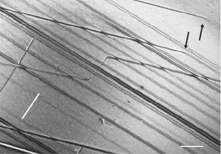
The places of the transition are marked by black arrows. In Fig. 10.29, these
inclined planes are also imaged edge-on. With reference to the diffraction pat-
tern in Fig. 10.6 (Fig. 10.29 is slightly rotated against Fig. 10.6), these planes
may be indexed (0
¯
1104). The mode of motion on these planes is a combination
of climb and glide. The inclined trace i in the middle of the figure changes
into the direction of the Burgers vector or the tensile direction, marked by g,
and back. The corresponding plane of motion is imaged edge-on, too. It may
be indexed (01
¯
100). This plane is a glide plane of these dislocations.
Similar processes are illustrated in the first sequence of the next video with
another dislocation iteratively changing its plane of motion.
Video 10.7. Climb and glide motion of a dislocation in d-Al–Ni–Co: In the first
part, the dislocation D extends approximately perpendicular to the periodic axis.
The traces directly connected with the dislocation are parallel to the periodic direc-
tion. Afterwards, the dislocation shifts to a plane with inclined traces, which have the
428 10 Quasicrystals
1μm
TD
c
i
i
i
g
Fig. 10.29. Micrograph showing traces of periodic dislocations moving on different
planes. From [666]. Copyright Mater. Res. Soc. (2005)
same orientation on the surface as the traces i in Fig. 10.29. Later on, it moves again
on the same plane as at the beginning of the recording. In contrast to Fig. 10.29,
the planes with the inclined trace and with the trace in the direction of the periodic
axis are not imaged edge-on. Considering the ratio between the widths of the two
traces, the corresponding planes of motion may be indexed (0
¯
1002) for the inclined
trace and (01000) for the trace in the direction of the periodic axis. In principle,
the planes of motion of a dislocation can change by glide and cross glide. The Burg-
ers vector would then be parallel to the intersection line between the two planes,
which is parallel to a quasiperiodic direction. These Burgers vectors are, however,
extinguished under the present imaging conditions with a g vector in the periodic
direction. Therefore, it is supposed that the dislocation also has a periodic Burg-
ers vector, since, according to [720], only these dislocations assume line directions
perpendicular to the periodic axis. Thus, the dislocation is a pure edge dislocation.
Consequently, the mode of motion is a combination of climb and glide for the inclined
traces, and it is a pure glide motion for the other one. The occurrence of the glide
motion is surprising, since in the current geometry, there should be no glide force in
a specimen with a homogeneous cross section. A glide force acting on the dislocation
could be due to the inhomogeneous shape of the microtensile specimen. The second
part of the video shows essentially the same. Now the dislocation changes between a
plane which is probably inclined with respect to the tenfold axis and the one normal
to it.
The dislocation velocities in the different modes of motion are quite different.
Measurements from the video recording yield 1.1and7nms
−1
for glide, and
325 and 285 nm s
−1
for the combination of climb and glide. In the same speci-
men area, a dislocation moved on the climb plane at a velocity of 460 nm s
−1
.
This shows that even for the periodic dislocations the glide velocity may be
much lower than the climb velocity. However, because of the very different
forces acting, the relation between the velocities does certainly not describe
the relation of the dislocation mobilities on the different planes.
10.3 Microscopic Observations of Dislocations 429
Both the macroscopic experiments in the A
orientation and the in situ
experiments show another set of dislocations with mixed Burgers vectors
marked by M in Fig. 10.26a. They move on planes containing the periodic
axis. The dislocation MCM expands by the curved segment C moving upwards
thus trailing the long straight dislocations labeled M. Accordingly, the long
straight dislocations parallel to the periodic axis do not represent the mobile
parts of the mixed dislocations. The mode of motion can be determined only
by indexing both the plane of motion and the Burgers vector. The determi-
nation of the Burgers vector was not possible during the in situ experiments
because of the unsuitable imaging conditions with most g vectors (see above,
Fig. 10.26b). As the plane of motion contains the tensile direction, neither
a glide nor a climb force from the applied load acts on the dislocations in
a macroscopic sense. Thus, these dislocations are equivalent to set B in i-
Al–Pd–Mn. Dislocation velocities were measured from a video recording of
a moving mixed dislocation segment as well as periodic dislocations on the
climb system. At the same applied stress, the dislocations on the climb system
are 20 times faster than the mixed dislocation.
As described above (Fig. 10.28), dislocations with periodic Burgers vec-
tors can interact with dislocations with mixed Burgers vectors. In most cases,
however, the moving periodic dislocations cut the mixed ones without a vis-
ible sign of reaction (third sequence in Video 10.6). However, sometimes the
reaction takes place as in the following video.
Video 10.8. Reaction between a dislocation with a periodic Burgers vector and
onewithamixedBurgersvectorinad-Al–Ni–Co single quasicrystal: The event
is marked by a yellow dot. The periodic dislocation exhibits a sharp knee, like
the dislocations marked by arrows in Fig. 10.26a. It moves to the left towards the
mixed dislocation. The latter shows a similar curved shape as that in Fig. 10.26a.
Both dislocations attract each other and join to form a segment of the product
dislocation. At the same time, the climbing periodic dislocation segment is shifted
onto a parallel climb plane (downwards in the video) due to the mutual elastic
interaction. The latter segment is fixed at the junction with the product dislocation
and starts to extend on the new climb plane (E). Later on, the segment indicated by
the straight yellow line moves back (upwards in the figure) and removes the product
dislocation. As a result, the mixed dislocation is restored and moves slowly upwards
while the periodic dislocation resumes its motion on the new climb plane. The dark
contrasts mark the traces of the dislocation motion.
In other cases, the same dislocation reaction results in the formation of a
dislocation source, as demonstrated in the video.
Video 10.9. Dislocation reaction and formation of a dislocation source in a d-Al–
Ni–Co single quasicrystal: Several dislocations with a periodic Burgers vector move
on the climb plane from right to left close to the bowed part of the dislocation
M with a mixed Burgers vector. After the mixed dislocation has slowly proceeded
upwards, the periodic dislocation following P reacts with the mixed one to form a
junction. Now, however, the segment of the periodic dislocation remains attached
to the junction and draws a long dislocation towards the left side. After the new
430 10 Quasicrystals
1 µm
(a)
a
b
c
d
(b)
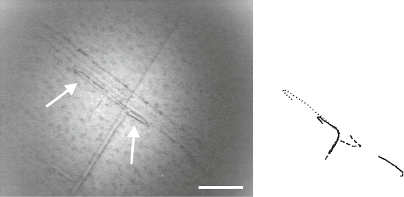
Fig. 10.30. Video frame of a dislocation climb source in d-Al–Ni–Co (a)and
schematic of several stages of the source (b). From [666]. Copyright Mater. Res.
Soc. (2005)
long segment of the periodic dislocation parallel to the specimen surface escaped
through the surface, the remaining new dislocation moves out of the image area
and the segment attached to the junction rotates to the right side of the mixed
dislocation and expands there. Finally, the source has emitted a dislocation moving
to the left whereas the rotating arm of the source has already turned to the right side
(arrows), with the source being restored, as illustrated in Fig. 10.30a. Some stages
of the operation of the source are schematically drawn in Fig. 10.30b. Afterwards,
the source continues its revolutions. After each revolution, the rotating segment
shifts slightly down onto a parallel plane. In the second part of the video, this spiral
character of the source is clearly visible.
Dislocation sources operating with climbing dislocations are called Bardeen-
Herring sources [724]. Several sources of this kind have been observed,
emitting tens of dislocations each. Owing to the spiral character, the generated
deformation bands grow in width.
During the observation of one source, the load was changed to study
the dynamic dislocation behavior. From the video recordings, the frequency
of the revolutions of the source f
source
was determined as a function of
the load F . In Fig. 10.31a, the results are plotted in a double-logarithmic
scale. Each symbol corresponds to one revolution of the source. During the
first part of the experiment, about 30 dislocations were emitted from the
source. The frequency of the source decreased only slightly while the load
remained almost constant (downward open triangles). Afterwards the speci-
men was partly unloaded until the source almost stopped to revolve. In the
plot of Fig. 10.31a, this phase of the experiment is characterized by a lin-
ear decrease of the frequency of the source with a load or stress exponent
m
sc ul
=dln(f
source
)/dlnF =dln(f
source
)/dlnσ =7.1. Afterwards, the spec-
imen was reloaded until fracture (full upward triangles). The figure shows that
unloading and reloading are reversible over the main part of the load range.
The reloading curve is linear, too, yielding a stress exponent of m
sc l
=4.4.

10.4 Macroscopic Deformation Parameters 431
In[F (N)]
In [f
source
(s
−1
)]
1.8 2.0 2.2 2.4
−5
−4
−3
−2
−1
m'
sc ul
= 7.1
m'
sc l
= 4.4
(a)
In[F (N)]
In [v
d
(nm s
−1
)]
1.8 2.0 2.2 2.4
3
4
5
6
m' = 3.9
(b)
Fig. 10.31. Load dependence of the frequency of the operation of a dislocation
source (a) and velocity of dislocations with periodic Burgers vectors moving away
from the source (b). Open downward triangles: unloading; full upward triangles:
re-loading. Data from [666]
For higher loads, the unloading and reloading curves do not coincide. In addi-
tion, the velocity v
d
of the dislocations emitted to the left was determined
from digitized video frames and plotted in Fig. 10.31b also as a function of
the load. This curve is linear, too, yielding a load or stress exponent of the
dislocation velocity of m
=dlnv
d
/dlnF =dlnv
d
/dlnσ =3.9.
In summarizing this section, the following may be stated.
• At high temperatures, dislocations in icosahedral Al–Pd–Mn quasicrystals
are mostly straight and oriented along crystallographic directions. They
move on crystallographic planes.
• The motion is smooth in a viscous way with a stress exponent of about
4–6.
• Many dislocations move on planes where they experience a climb force
but no glide force (set A), or even no force at all from the external load
(set B). The determination of both the Burgers vectors and the plane of
motion showed that climb is the dominating mode of dislocation motion
in icosahedral quasicrystals.
• The dislocations drag phason walls which disappear at high temperatures
by retiling.
• At low temperatures, the dislocations are curved.
• In decagonal quasicrystals, periodic dislocations may climb and glide. The
mode of motion of the quasiperiodic and mixed dislocations is not yet
clear.
10.4 Macroscopic Deformation Parameters
The whole methodology, which for more than 50 years had been designed to
study the plastic deformation of crystals, was applied to quasicrystals within
a few years. As diffusion is involved in the plastic deformation of quasicrys-
tals, respective data, usual deformation experiments at ambient pressure are
