Mattingly J.D., Heiser W.H., Pratt D.T. Aircraft Engine Design
Подождите немного. Документ загружается.

APPENDIX M: EXAMPLE MATERIAL PROPERTIES 633
2O
tm
J¢
i
40 ~ " 1200 F
"-.2
4 ,, 1795 F
~,~
\
2
0.1
percent total plastic
in
..... 0.5
percent total plastic strain
~-~
Rupture
I ] I l I I
tO0
tO00 I0,000
Time, hours
'Nimoni¢ 10S Extrmdled Bar'
I
2100 F, 4 hrs, AC + 1920 F, 16 hrs.
I
AC + 1560 F, 16 hi'=, AC
"~ ,¢~.,,~. "'-" ".~... "" "-,,
, ~"~\
, ~::~ 1500 F
\
\
-,,\
~'~'~ 1600 F
100,000
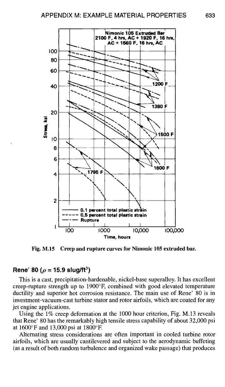
Fig. M.15 Creep and rupture curves for Nimonic 105 extruded bar.
Rene' 80 (p = 15.9 slug/ft 3)
This is a cast, precipitation-hardenable, nickel-base superalloy. It has excellent
creep-rupture strength up to 1900°F, combined with good elevated temperature
ductility and superior hot corrosion resistance. The main use of Rene' 80 is in
investment-vacuum-cast turbine stator and rotor airfoils, which are coated for any
jet engine applications.
Using the 1% creep deformation at the 1000 hour criterion, Fig. M.13 reveals
that Rene' 80 has the remarkably high tensile stress capability of about 32,000 psi
at 1600°F and 13,000 psi at 1800°E
Alternating stress considerations are often important in cooled turbine rotor
airfoils, which are usually cantilevered and subject to the aerodynamic buffeting
(as a result of both random turbulence and organized wake passage) that produces
634 AIRCRAFT ENGINE DESIGN
vibratory loads. It is especially important to avoid resonance between a regular
upstream disturbance and a natural frequency of the rotor airfoils.
Thermal stresses can cause low-cycle fatigue failure if the limits given in
Fig. M.14 are reached. This means that cooled airfoils must be designed with the
greatest care so that no local areas of large thermal stress are created at any time
during the normal engine operation. In particular, it can be readily seen that a thin
airfoil "skin" with a large temperature difference between coolant and mainstream
will not last long.
Nimonic 105 (p = 15.5 slug/ft 3)
This is a wrought nickel-cobalt-chromium-base superalloy having creep and
oxidation resistances that make it suitable for service at temperatures up to 1750°E
It is used for turbine rotor airfoils, disks, forgings, ring sections, bolts, and fasteners.
The data of Fig. M.15 show that Nimonic 105 falls between Rene' 80 and
Hastelloy X in tensile strength. Under the same ground rules, one finds a stress of
about 17,000 psi at 1600°F and perhaps 3000 psi at 1800°E No data were given
for the low-cycle fatigue behavior of Nimonic 105.
Reference
IAerospace Structural Metals Handbook, Battelle Memorial Inst., Columbus Lab.,
Columbus, OH, 1984.
Appendix N
Turbine Engine Life Management
N.1 Introduction to the Engine Lifing Process
While performing their intended aerodynamic tasks, the rotating compressor and
turbine parts must also be almost certain to last the design lifetime of the engine. The
turbine engine lifing (pronounced "life"-ing) process is evolutionary and has been
unfolding over the past 50 years. In various degrees it is affected today by many
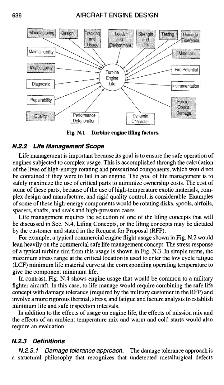
of the factors depicted in Fig. N. 1. These factors have all evolved through lessons
learned and state-of-the-art changes. Some of the most notable advances that have
been made are in the areas indicated by the shaded blocks in Fig. N. 1. Some
of these include: 1) finite element modeling techniques used in stress analysis;
2) improved materials (strength, temperature capability, life, fracture toughness);
3) engine controls; 4) testing techniques; 5) manufacturing and inspection; 6) sur-
face treatments that instill beneficial residual stresses such as laser shock peening;
7) data recording systems for usage monitoring; and 8) usage tracking systems.
When taken together, all of these advances in the "state of art" have had a very
positive effect on the ability to predict engine component life and on safety.
N.2 Engine Life Management
N.2.1 Lessons Learned
Through many development programs (commercial and military) and customer
engine problems the following summary of generic lessons learned has been
collected:
1) It is dangerous to assume defect-free structures in safety of flight components.
2) Critical parts and potential failure modes must be identified early in devel-
opment and appropriate control measures implemented.
3) Thermal and vibratory environments must be identified early in engine
development.
4) For complex components analytic stresses must be verified by testing.
5) Materials and processes must be adequately characterized (particularly, the
fracture properties).
6) Design stress spectra, component test spectra, and full scale engine test
spectra must be based on the anticipated service usage of the engine.
7) Potential engine/airframe structural interactions must be defined and taken
into account.
8) Closed-loop management procedures must be defined and enforced through
the application of realistic inspection and maintenance requirements, individual
engine tracking procedures, deficiency reporting, and updates in procedures based
on actual usage.
635
636 AIRCRAFT ENGINE DESIGN
Fig. N.I Turbine engine lifing factors.
N.2.2 Life Management Scope
Life management is important because its goal is to ensure the safe operation of
engines subjected to complex usage. This is accomplished through the calculation
of the lives of high-energy rotating and pressurized components, which would not
be contained if they were to fail in an engine. The goal of life management is to
safely maximize the use of critical parts to minimize ownership costs. The cost of
some of these parts, because of the use of high-temperature exotic materials, com-
plex design and manufacture, and rigid quality control, is considerable. Examples
of some of these high-energy components would be rotating disks, spools, airfoils,
spacers, shafts, and seals and high-pressure cases.
Life management requires the selection of one of the lifing concepts that will
be discussed in Sec. N.4, Lifing Concepts, or the lifing concepts may be dictated
by the customer and stated in the Request for Proposal (RFP).
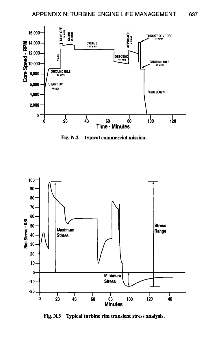
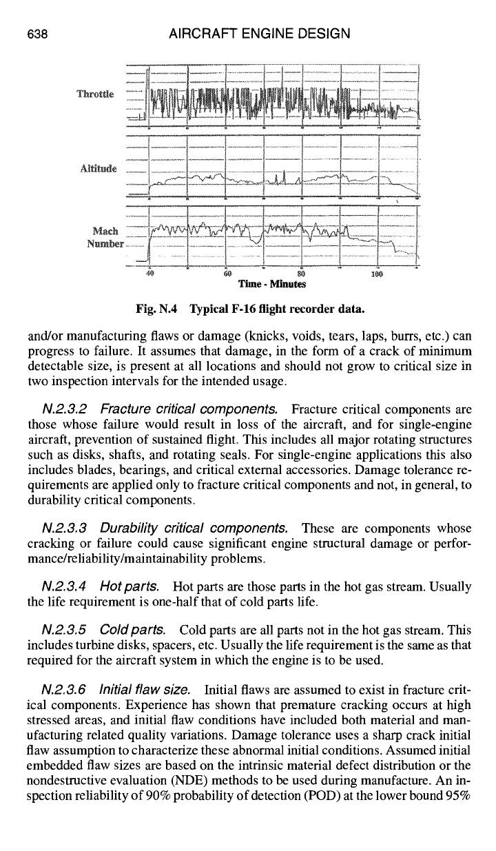
For example, a typical commercial engine flight usage shown in Fig. N.2 would
lean heavily on the commercial safe life management concept. The stress response
of a typical turbine rim from this usage is shown in Fig. N.3. In simple terms, the
maximum stress range at the critical location is used to enter the low cycle fatigue
(LCF) minimum life material curve at the corresponding operating temperature to
give the component minimum life.
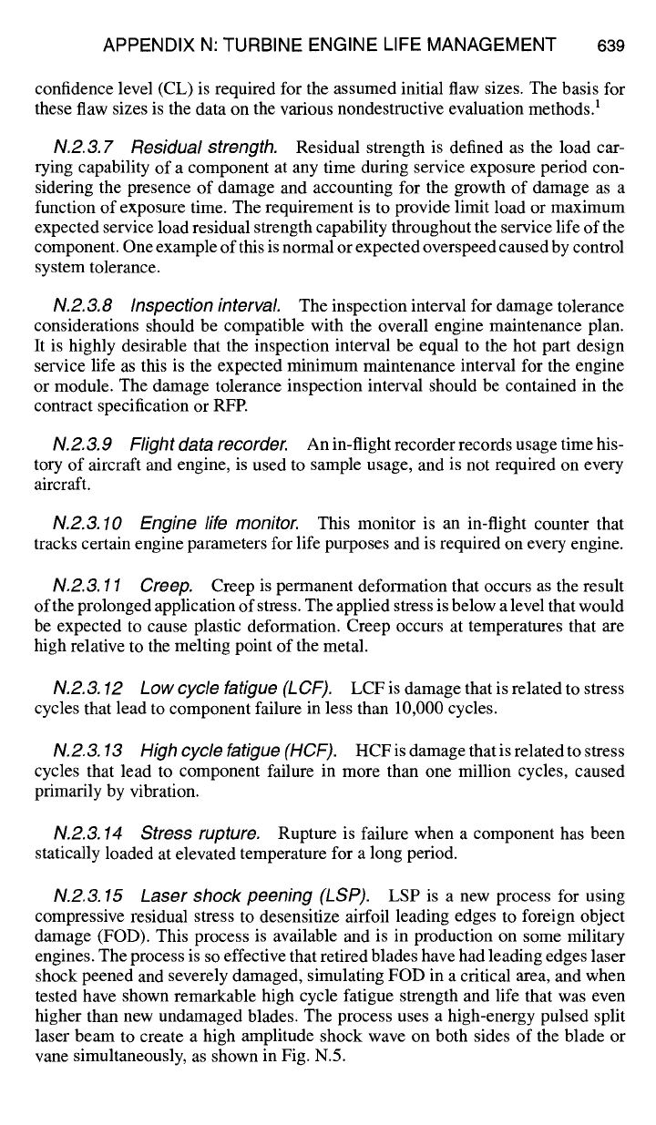
In contrast, Fig. N.4 shows engine usage that would be common to a military
fighter aircraft. In this case, to life manage would require combining the safe life
concept with damage tolerance (required by the military customer in the RFP) and
involve a more rigorous thermal, stress, and fatigue and facture analysis to establish
minimum life and safe inspection intervals.
In addition to the effects of usage on engine life, the effects of mission mix and
the effects of an ambient temperature mix and warm and cold starts would also
require an evaluation.
N.2.3 Definitions
N.2.3.1 Damage tolerance approach.
The damage tolerance approach is
a structural philosophy that recognizes that undetected metallurgical defects
APPENDIX N: TURBINE ENGINE LIFE MANAGEMENT 637
16,000--
~14,000--
a.
n.-
,12,000--
~.10,O00--
or)
.o 8,000-
o
¢J
6,000-
4,000-
2,000 -
~" THRUST REVERSE
p.~ ~ ~j~ 0 z 22SECS
DESCEND
~l
II
GROUNO~OLE
-- I.I .......
GROUND ID E
85 MINS
START UP
SECS
SHUTDOWN
I I I I I I
20 40 60 80 100 120
Time - Minutes
Fig. N.2 Typical commercial mission.
100--
90--
80--
70--
60--
~', 50--
i
.E 3o-
20-
10-
O-
-10-
-20 -
0
\
Maximum
Stress
i S
Minimum
Stress ~,,.~
I I I I I I
20 40 60 80 100 120
Minutes
Stress
Range
140
Fig. N.3 Typical turbine rim transient stress analysis.
638 AIRCRAFT ENGINE DESIGN
Throttle
Altitude
Math
i,,_" ...... ~
Number
..........
4O
60 80 100
Time - Minutes
Fig. N.4 Typical F-16 flight recorder data.
and/or manufacturing flaws or damage (knicks, voids, tears, laps, burrs, etc.) can
progress to failure. It assumes that damage, in the form of a crack of minimum
detectable size, is present at all locations and should not grow to critical size in
two inspection intervals for the intended usage.
N.2.3.2 Fracture critical components.
Fracture critical components are
those whose failure would result in loss of the aircraft, and for single-engine
aircraft, prevention of sustained flight. This includes all major rotating structures
such as disks, shafts, and rotating seals. For single-engine applications this also
includes blades, bearings, and critical external accessories. Damage tolerance re-
quirements are applied only to fracture critical components and not, in general, to
durability critical components.
N.2.&3 Durability critical components. These are components whose
cracking or failure could cause significant engine structural damage or perfor-
mance/reliability/maintainability problems.
N.2.&4 Hot parts. Hot parts are those parts in the hot gas stream. Usually
the life requirement is one-half that of cold parts life.
N.2.3.5 Coldparts. Cold parts are all parts not in the hot gas stream. This
includes turbine disks, spacers, etc. Usually the life requirement is the same as that
required for the aircraft system in which the engine is to be used.
N.2.3.6 Initial flaw size. Initial flaws are assumed to exist in fracture crit-
ical components. Experience has shown that premature cracking occurs at high
stressed areas, and initial flaw conditions have included both material and man-
ufacturing related quality variations. Damage tolerance uses a sharp crack initial
flaw assumption to characterize these abnormal initial conditions. Assumed initial
embedded flaw sizes are based on the intrinsic material defect distribution or the
nondestructive evaluation (NDE) methods to be used during manufacture. An in-
spection reliability of 90% probability of detection (POD) at the lower bound 95%
APPENDIX N: TURBINE ENGINE LIFE MANAGEMENT 639
confidence level (CL) is required for the assumed initial flaw sizes. The basis for
these flaw sizes is the data on the various nondestructive evaluation methods. 1
N.2.3.7 Residual strength.
Residual strength is defined as the load car-
rying capability of a component at any time during service exposure period con-
sidering the presence of damage and accounting for the growth of damage as a
function of exposure time. The requirement is to provide limit load or maximum
expected service load residual strength capability throughout the service life of the
component. One example of this is normal or expected overspeed caused by control
system tolerance.
N.2.3.8 Inspection interval
The inspection interval for damage tolerance
considerations should be compatible with the overall engine maintenance plan.
It is highly desirable that the inspection interval be equal to the hot part design
service life as this is the expected minimum maintenance interval for the engine
or module. The damage tolerance inspection interval should be contained in the
contract specification or RFP.
N.2.3.9 Flight data recorder.
An in-flight recorder records usage time his-
tory of aircraft and engine, is used to sample usage, and is not required on every
aircraft.
N.2.3.10 Engine life monitor.
This monitor is an in-flight counter that
tracks certain engine parameters for life purposes and is required on every engine.
N.2.3. 11 Creep.
Creep is permanent deformation that occurs as the result
of the prolonged application of stress. The applied stress is below a level that would
be expected to cause plastic deformation. Creep occurs at temperatures that are
high relative to the melting point of the metal.
N.2.3.12 Low cycle fatigue (LCF).
LCF is damage that is related to stress
cycles that lead to component failure in less than 10,000 cycles.
N.2.3.13 High cycle fatigue (HCF).
HCFisdamagethatisrelatedtostress
cycles that lead to component failure in more than one million cycles, caused
primarily by vibration.
N.2.3.14 Stress rupture.
Rupture is failure when a component has been
statically loaded at elevated temperature for a long period.
N.2.3.15 Laser shock peening (LSP).
LSP is a new process for using
compressive residual stress to desensitize airfoil leading edges to foreign object
damage (FOD). This process is available and is in production on some military
engines. The process is so effective that retired blades have had leading edges laser
shock peened and severely damaged, simulating FOD in a critical area, and when
tested have shown remarkable high cycle fatigue strength and life that was even
higher than new undamaged blades. The process uses a high-energy pulsed split
laser beam to create a high amplitude shock wave on both sides of the blade or
vane simultaneously, as shown in Fig. N.5.
640 AIRCRAFT ENGINE DESIGN
OSCILLATOR
PRE-AMPLIFIER
, , [oo,- o ol
DI
AMPL,F,ERSIul I I
DI
TARGET
AMPLIFIERS
<
Fig. N.5 Pulsed laser beam used in peening.
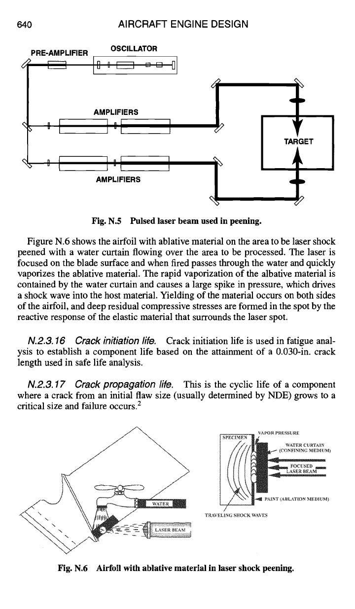
Figure N.6 shows the airfoil with ablative material on the area to be laser shock
peened with a water curtain flowing over the area to be processed. The laser is
focused on the blade surface and when fired passes through the water and quickly
vaporizes the ablative material. The rapid vaporization of the albative material is
contained by the water curtain and causes a large spike in pressure, which drives
a shock wave into the host material. Yielding of the material occurs on both sides
of the airfoil, and deep residual compressive stresses are formed in the spot by the
reactive response of the elastic material that surrounds the laser spot.
N.2.3.16 Crack initiation life.
Crack initiation life is used in fatigue anal-
ysis to establish a component life based on the attainment of a 0.030-in. crack
length used in safe life analysis.
N.2.3.17 Crack propagation fife.
This is the cyclic life of a component
where a crack from an initial flaw size (usually determined by NDE) grows to a
critical size and failure occurs. 2
"~ -~- "~ ~ LASER BEAM
VAPOR PRESSURE
~M)WATER CURTAIN
FOCUSED ll ~
LASERBEAM "
/
TRAVELING SHOCK WAVES
Fig. N.6 Airfoil with ablative material in laser shock peening.
APPENDIX N: TURBINE ENGINE LIFE MANAGEMENT 641
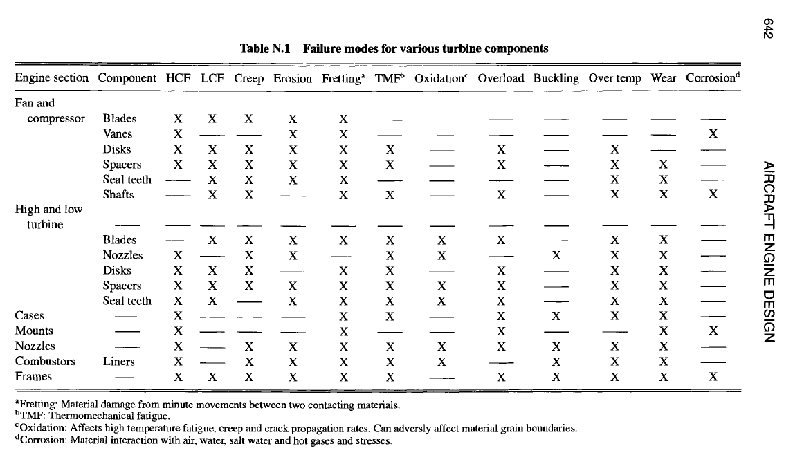
N.3 Engine Failure Modes
Each component of the engine can react differently, from a life standpoint,
to the duty cycle to which the engine is subjected. For example, turbine blades
and vanes can be critical in creep or stress rupture if the usage requires long
periods of time at maximum power. On the other hand, a large number of throttle
transients in this duty cycle can alter the failure mode of the same turbine blade
and vanes to that of LCF. Because of this sensitivity, engine usage must be moni-
tored for significant changes relative to that assumed for design. Table N. 1 shows
the failure modes for various components in the engine for typical usage.
N.4 Lifing Concepts
Lifing concepts have evolved and improved since the early period of the gas
turbine engine. Early on, passing a 150-h test was the main "pass or fail" criteria
used to qualify a new engine design to enter production and service. Engine life
development and life prediction techniques evolved mostly in response to dura-
bility problems, customer demands, and/or regulatory involvement. The safe life
(see Fig. N.7) and damage tolerance concepts have been the two most widely
used design methods for producing components to meet life requirements. More
recently, however, the combination of both life concepts, as shown in Fig. N.8, is
the preferred lifing method for both commercial and military and is required by
the military in their engine structural development programs.
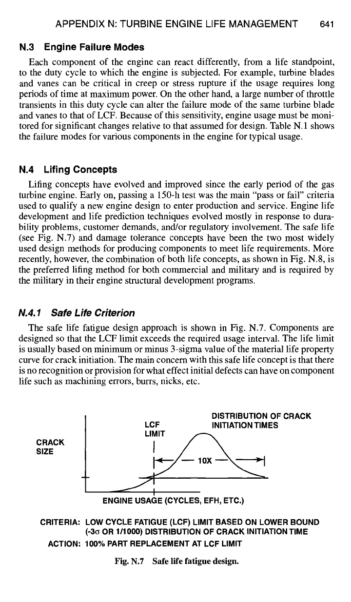
N.4.1 Safe Life
Criterion
The safe life fatigue design approach is shown in Fig. N.7. Components are
designed so that the LCF limit exceeds the required usage interval. The life limit
is usually based on minimum or minus 3-sigma value of the material life property
curve for crack initiation. The main concern with this safe life concept is that there
is no recognition or provision for what effect initial defects can have on component
life such as machining errors, burrs, nicks, etc.
CRACK
SIZE
DISTRIBUTION OF CRACK
LCF INiTIATiON TIMES
I
ENGINE USAGE (CYCLES, EFH, ETC.)
CRITERIA: LOW CYCLE FATIGUE (LCF) LIMIT BASED ON LOWER BOUND
(-3G OR 1/1000) DISTRIBUTION OF CRACK INITIATION TIME
ACTION: 100% PART REPLACEMENT AT LCF LIMIT
Fig. N.7 Safe life fatigue design.
642 AIRCRAFT ENGINE DESIGN
0
r,)
©
e~
E ~
• ~ ©
0
r,.)
o
0
r~
0
©
I
0
o
r..)
"0
0
.t-
o
o
• .~ -~