Mattingly J.D., Heiser W.H., Pratt D.T. Aircraft Engine Design
Подождите немного. Документ загружается.

APPENDIX L: PROPELLER DESIGN TOOLS 613
r/p
1.o
' ' ' I ' ' ' I ' ' ' I ' ' ' I ' ' '
0.8
Cr
0.7
0.6 1
0.5 0
1 1.2 1.4 1.6 1.8 2
V~ lVo
4
3
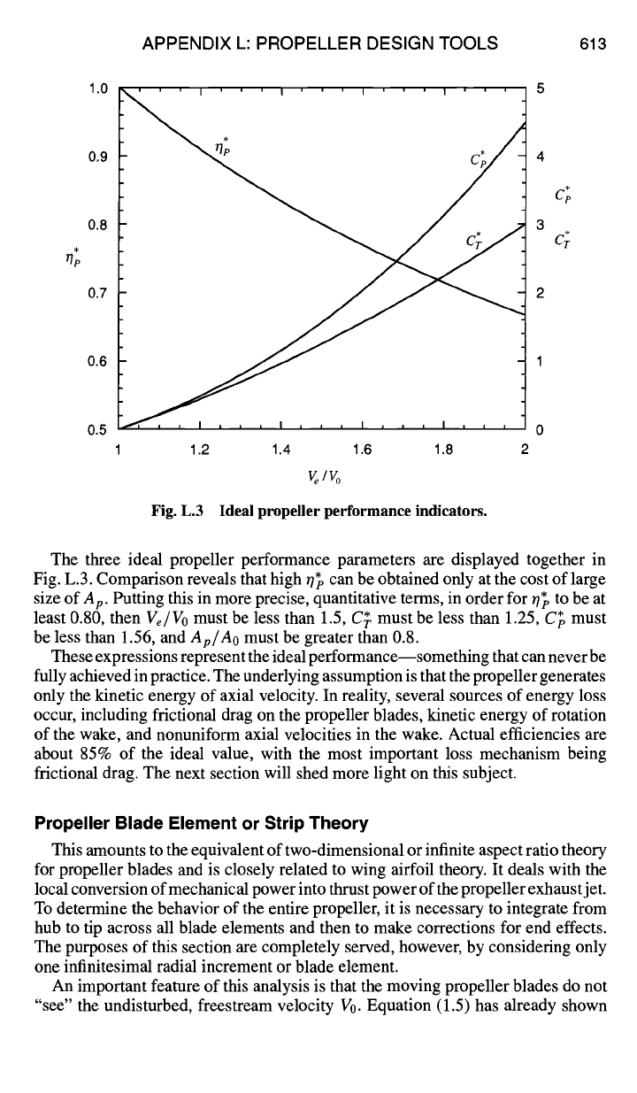
Fig. L.3 Ideal propeller performance indicators.
The three ideal propeller performance parameters are displayed together in
Fig. L.3. Comparison reveals that high r/~o can be obtained only at the cost of large
size of
Ap.
Putting this in more precise, quantitative terms, in order for ~7~ to be at
least 0.80, then
Ve/Vo
must be less than 1.5, C~. must be less than 1.25, C~ must
be less than 1.56, and
Ap/Ao
must be greater than 0.8.
These expressions represent the ideal performance--something that can never be
fully achieved in practice. The underlying assumption is that the propeller generates
only the kinetic energy of axial velocity. In reality, several sources of energy loss
occur, including frictional drag on the propeller blades, kinetic energy of rotation
of the wake, and nonuniform axial velocities in the wake. Actual efficiencies are
about 85% of the ideal value, with the most important loss mechanism being
frictional drag. The next section will shed more light on this subject.
Propeller Blade Element or Strip Theory
This amounts to the equivalent of two-dimensional or infinite aspect ratio theory
for propeller blades and is closely related to wing airfoil theory. It deals with the
local conversion of mechanical power into thrust power of the propeller exhaust jet.
To determine the behavior of the entire propeller, it is necessary to integrate from
hub to tip across all blade elements and then to make corrections for end effects.
The purposes of this section are completely served, however, by considering only
one infinitesimal radial increment or blade element.
An important feature of this analysis is that the moving propeller blades do not
"see" the undisturbed, freestream velocity V0. Equation (1.5) has already shown
614 AIRCRAFT ENGINE DESIGN
Tip
Cross- ~Blade
Element~ ~'dr
Total Airfoil Force Tangential Force
~dR ~dQ/r
Lift/__
I
~\ I ~ Drag
I
I 4~ ~k I // / / Geometric
s,i Pitch
~ - ~ = Angle of Attack
••
Pitch or
Advance
Relative Wind, V~ Angle
a ')J2r
tan y = D/L = CD/CL
(l+a) V0
tan # =
Vo(l+a)/(1-a')Or
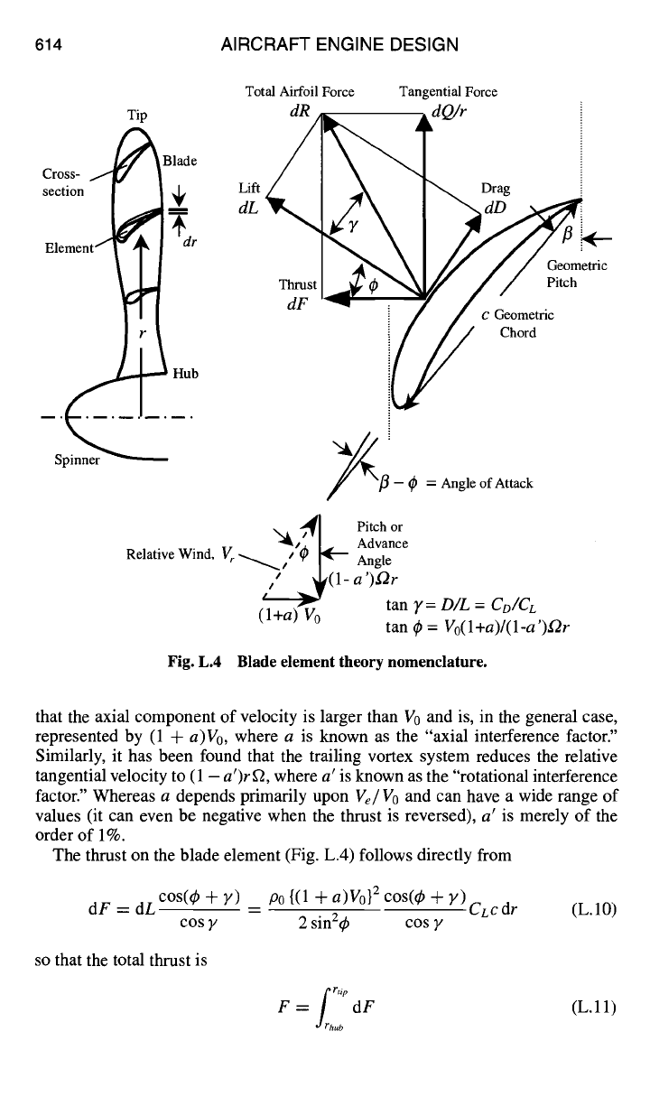
Fig. L.4 Blade element theory nomenclature.
that the axial component of velocity is larger than V0 and is, in the general case,
represented by (1 +
a)Vo,
where a is known as the "axial interference factor."
Similarly, it has been found that the trailing vortex system reduces the relative
tangential velocity to (1 -
a')rfL
where a' is known as the "rotational interference
factor." Whereas a depends primarily upon
Ve/Vo
and can have a wide range of
values (it can even be negative when the thrust is reversed), a' is merely of the
order of 1%.
The thrust on the blade element (Fig. L.4) follows directly from
dF = dL c°s(~ + y) -- P0 {(1 + a)V0} 2 cos(~b -F
Y)CLcdr
(L.10)
cos y 2 sin2~ cos y
so that the total thrust is
frf tip
F = dF (L.11)
ub
APPENDIX L: PROPELLER DESIGN TOOLS 615
The tangential torque on the blade element follows directly from
dQ = rdL
sln(q~ + y) _
cos y 2 sin 2 ~b cos y
p0{(1 + a)V0} 2 sin(~b +
Y)CLC rdr
(L.12)
so that the total torque is
frh 'tip
Q = dQ (L.13)
ub
The most interesting relationship, which allows the evaluation of the local or blade
element efficiency of conversion of mechanical power into thrust power, comes
from the definition of the blade element efficiency Oe.
.__VodF
(V0)( dd@/r )
Oe
which, from the relative wind velocity and total airfoil force triangles of Fig. L.4,
becomes
1 -
a' tan 4,
~e •
(L.14)
1 + a tan(4~ + y)
The local conversion efficiency therefore depends primarily upon a, y, and q~.
If a and ~b are held constant, t/e must decrease as y increases, which certainly
makes sense because that decreases dF while increasing
dQ/r.
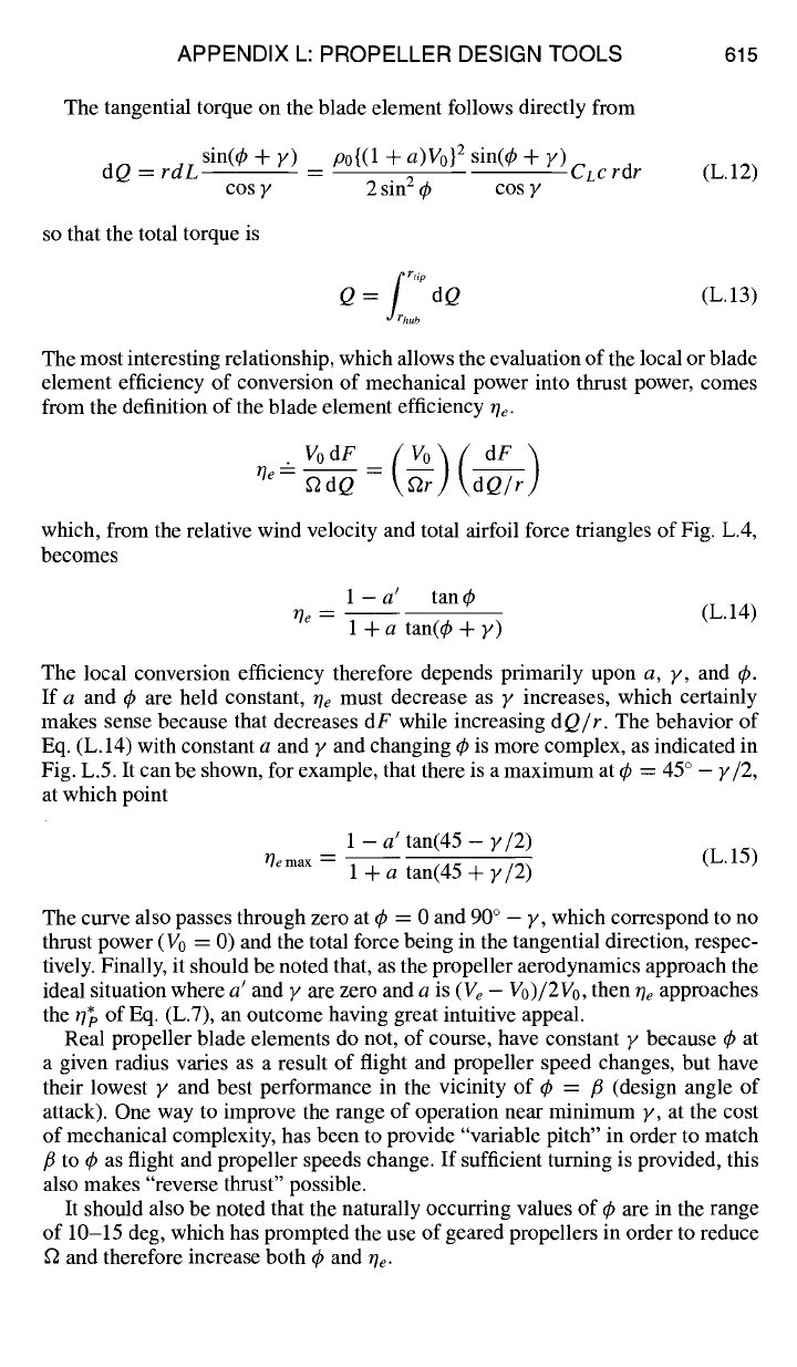
The behavior of
Eq. (L.14) with constant a and y and changing q~ is more complex, as indicated in
Fig. L.5. It can be shown, for example, that there is a maximum at q~ = 45 ° -
y/2,
at which point
1 - a' tan(45 - y/2)
t]ema x =
(L.15)
1 + a tan(45 + y/2)
The curve also passes through zero at ~b = 0 and 90 ° - y, which correspond to no
thrust power (V0 = 0) and the total force being in the tangential direction, respec-
tively. Finally, it should be noted that, as the propeller aerodynamics approach the
ideal situation where
a' and y are
zero and a is
(Ve - Vo)/2Vo,
then Oe approaches
the ~ of Eq. (L.7), an outcome having great intuitive appeal.
Real propeller blade elements do not, of course, have constant y because 4) at
a given radius varies as a result of flight and propeller speed changes, but have
their lowest y and best performance in the vicinity of 4, = /~ (design angle of
attack). One way to improve the range of operation near minimum y, at the cost
of mechanical complexity, has been to provide "variable pitch" in order to match
/3 to q~ as flight and propeller speeds change. If sufficient turning is provided, this
also makes "reverse thrust" possible.
It should also be noted that the naturally occurring values of q~ are in the range
of 10-15 deg, which has prompted the use of geared propellers in order to reduce
f2 and therefore increase both q~ and Oe.
616 AIRCRAFT ENGINE DESIGN
1.0
~e
0.5
0.0
I I I I I I I I
%
/
30 60 90
¢ (o)
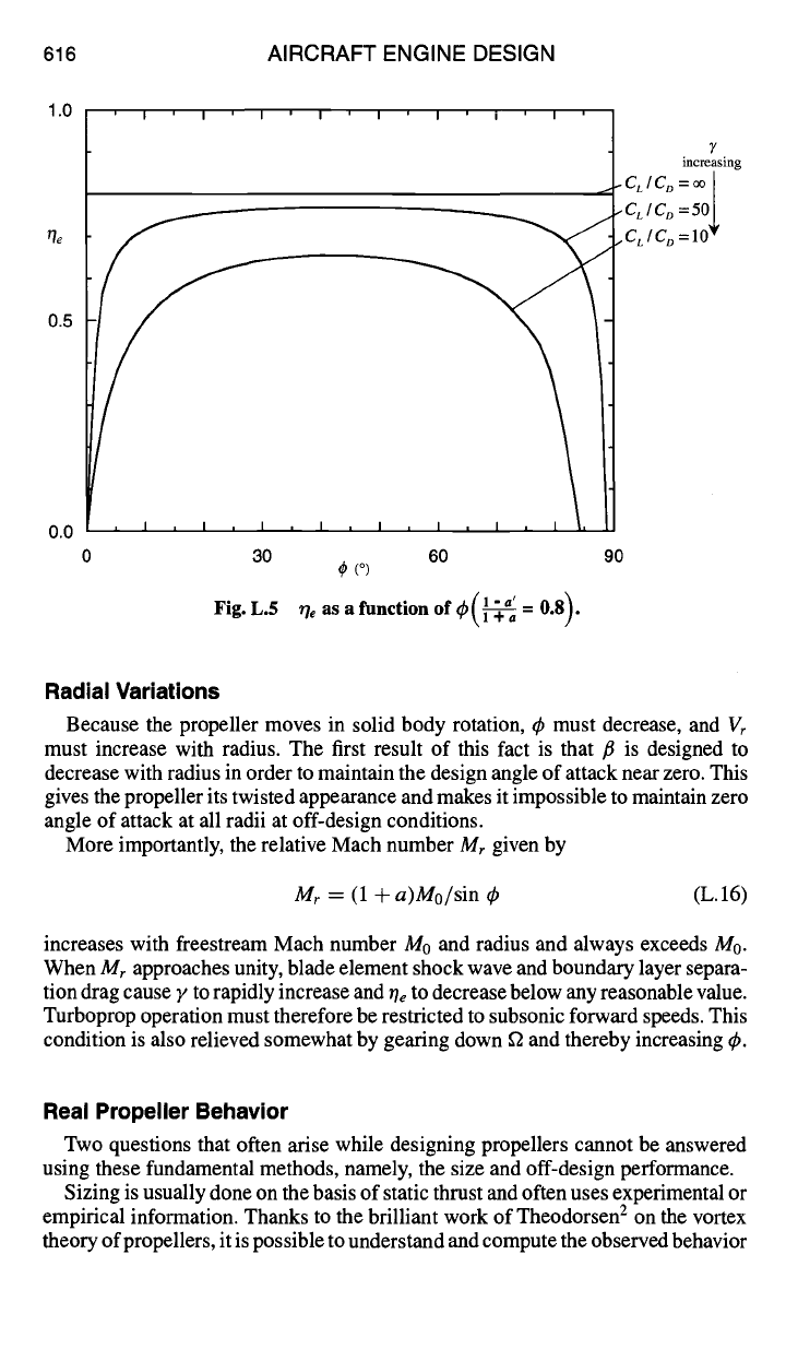
Fig. L.5 r/e as a function of ~b(~ = 0.8).
7
increasing
.CLIC o =oo~
.CL I C ~
=50
.CLIC o
=10
Radial Variations
Because the propeller moves in solid body rotation, ~ must decrease, and Vr
must increase with radius. The first result of this fact is that fl is designed to
decrease with radius in order to maintain the design angle of attack near zero. This
gives the propeller its twisted appearance and makes it impossible to maintain zero
angle of attack at all radii at off-design conditions.
More importantly, the relative Mach number
Mr
given by
Mr
= (1 +
a)Mo/sin
(L.16)
increases with freestream Mach number M0 and radius and always exceeds M0.
When
Mr
approaches unity, blade element shock wave and boundary layer separa-
tion drag cause F to rapidly increase and Oe to decrease below any reasonable value.
Turboprop operation must therefore be restricted to subsonic forward speeds. This
condition is also relieved somewhat by gearing down f2 and thereby increasing ~b.
Real Propeller Behavior
Two questions that often arise while designing propellers cannot be answered
using these fundamental methods, namely, the size and off-design performance.
Sizing is usually done on the basis of static thrust and often uses experimental or
empirical information. Thanks to the brilliant work of Theodorsen 2 on the vortex
theory of propellers, it is possible to understand and compute the observed behavior
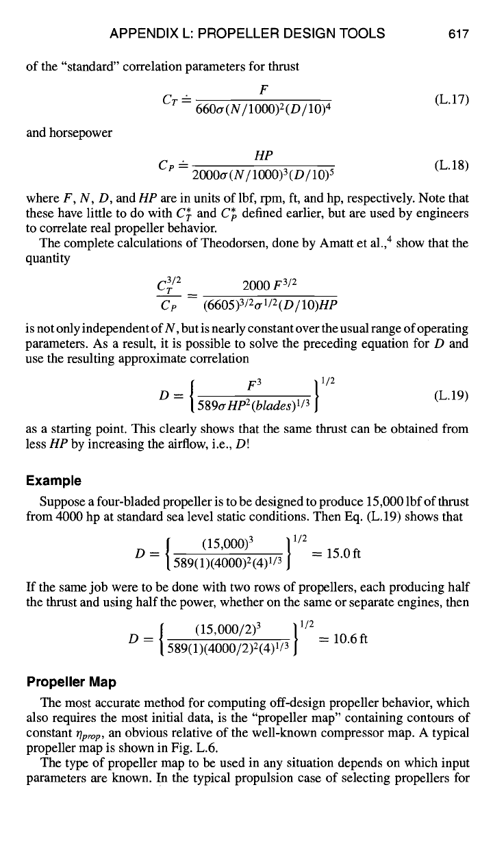
APPENDIX L: PROPELLER DESIGN TOOLS 617
of the "standard" correlation parameters for thrust
and horsepower
F
Cr -
(L.17)
660a (N / 1000)2 (D / 10)
4
HP
Cp -
(L. 18)
2000a
(N/1000)
3
(D/10)
5
where F, N, D, and
lip are
in units of lbf, rpm, fl, and hp, respectively. Note that
these have little to do with C~. and C~o defined earlier, but are used by engineers
to correlate real propeller behavior.
The complete calculations of Theodorsen, done by Amatt et al.,4 show that the
quantity
C3/2
2000
F 3/2
T
Cp (6605)3/2tr1/2(D/lO)HP
is not only independent of N, but is nearly constant over the usual range of operating
parameters. As a result, it is possible to solve the preceding equation for D and
use the resulting approximate correlation
D = 589aHp2(blades)l/3
(L.19)
as a starting point. This clearly shows that the same thrust can be obtained from
less
lip
by increasing the airflow, i.e., D!
Example
Suppose a four-bladed propeller is to be designed to produce 15,000 lbf of thrust
from 4000 hp at standard sea level static conditions. Then Eq. (L. 19) shows that
{ (15,000)3
}1/2
D = 589(1)(4000)2(4)1/3 = 15.0ft
If the same job were to be done with two rows of propellers, each producing half
the thrust and using half the power, whether on the same or separate engines, then
/ (15'000/2)3 }1/2
D ---- [ 589(~4)1/3 = 10.6ft
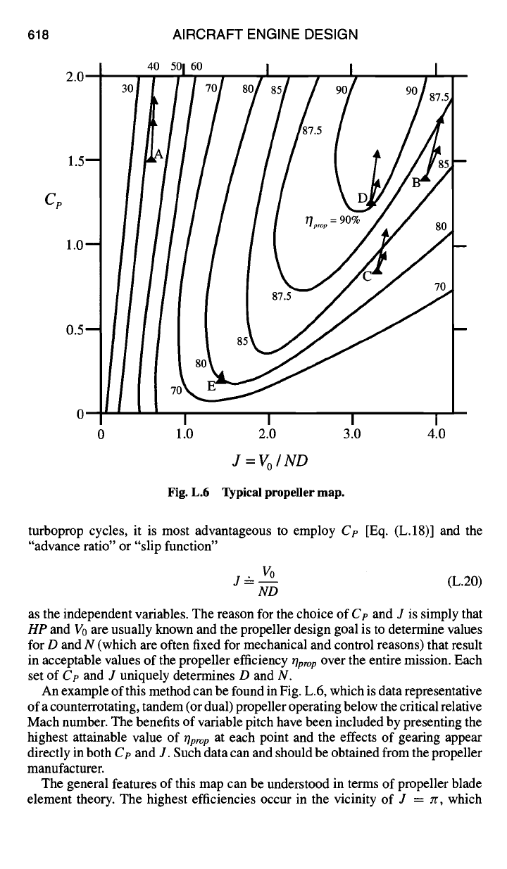
Propeller Map
The most accurate method for computing off-design propeller behavior, which
also requires the most initial data, is the "propeller map" containing contours of
constant
Oprop, an
obvious relative of the well-known compressor map. A typical
propeller map is shown in Fig. L.6.
The type of propeller map to be used in any situation depends on which input
parameters are known. In the typical propulsion case of selecting propellers for
618 AIRCRAFT ENGINE DESIGN
Cp
0 1.0 2.0 3.0 4.0
J=Vo/ ND
Fig. L.6 Typical propeller map.
turboprop cycles, it is most advantageous to employ
Ce
[Eq. (L.18)] and the
"advance ratio" or "slip function"
I10
J ---- -- (L.20)
ND
as the independent variables. The reason for the choice of Cp and J is simply that
HP and Vo are
usually known and the propeller design goal is to determine values
for D and N (which are often fixed for mechanical and control reasons) that result
in acceptable values of the propeller efficiency
rlprop
over the entire mission. Each
set of Cp and J uniquely determines D and N.
An example of this method can be found in Fig. L.6, which is data representative
of a counterrotating, tandem (or dual) propeller operating below the critical relative
Mach number. The benefits of variable pitch have been included by presenting the
highest attainable value of
17pro p
at each point and the effects of gearing appear
directly in both
Ce and J.
Such data can and should be obtained from the propeller
manufacturer.
The general features of this map can be understood in terms of propeller blade
element theory. The highest efficiencies occur in the vicinity of J = Jr, which
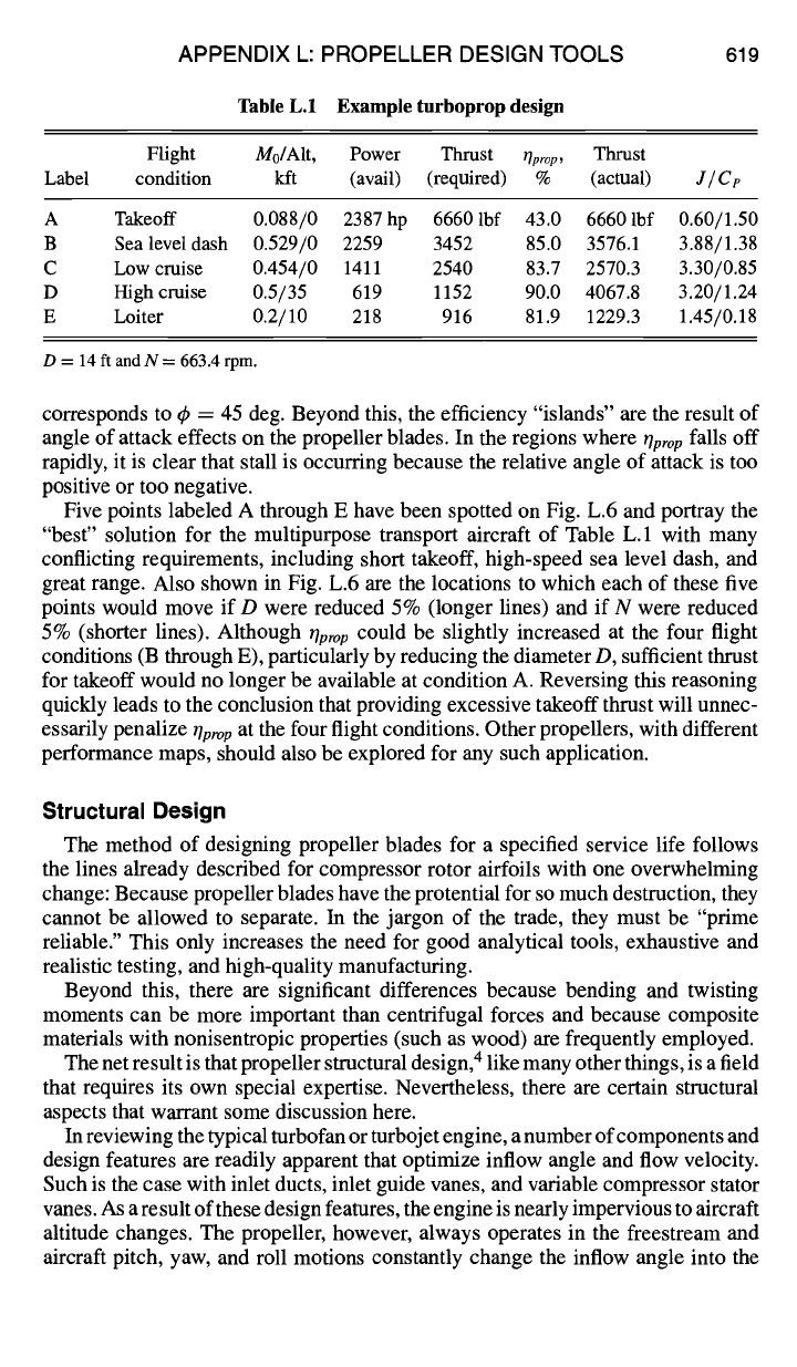
APPENDIX L: PROPELLER DESIGN TOOLS 619
Table L.I Example turboprop design
Flight M0/Alt, Power Thrust
rlprop,
Thrust
Label condition kft (avail) (required) % (actual)
J/Ce
A Takeoff 0.088/0 2387hp 66601bf 43.0 66601bf 0.60/1.50
B Sealeveldash 0.529/0 2259 3452 85.0 3576.1 3.88/1.38
C Low cruise 0.454/0 1411 2540 83.7 2570.3 3.30/0.85
D High cruise 0.5/35 619 1152 90.0 4067.8 3.20/1.24
E Loiter 0.2/10 218 916 81.9 1229.3 1.45/0.18
D = 14 ft and N = 663.4 rpm.
corresponds to 4' = 45 deg. Beyond this, the efficiency "islands" are the result of
angle of attack effects on the propeller blades. In the regions where
llpro p
falls off
rapidly, it is clear that stall is occurring because the relative angle of attack is too
positive or too negative.
Five points labeled A through E have been spotted on Fig. L.6 and portray the
"best" solution for the multipurpose transport aircraft of Table L. 1 with many
conflicting requirements, including short takeoff, high-speed sea level dash, and
great range. Also shown in Fig. L.6 are the locations to which each of these five
points would move if D were reduced 5% (longer lines) and if N were reduced
5% (shorter lines). Although
tiptop
could be slightly increased at the four flight
conditions (B through E), particularly by reducing the diameter D, sufficient thrust
for takeoff would no longer be available at condition A. Reversing this reasoning
quickly leads to the conclusion that providing excessive takeoff thrust will unnec-
essarily penalize
Oprop
at the four flight conditions. Other propellers, with different
performance maps, should also be explored for any such application.
Structural Design
The method of designing propeller blades for a specified service life follows
the lines already described for compressor rotor airfoils with one overwhelming
change: Because propeller blades have the protential for so much destruction, they
cannot be allowed to separate. In the jargon of the trade, they must be "prime
reliable." This only increases the need for good analytical tools, exhaustive and
realistic testing, and high-quality manufacturing.
Beyond this, there are significant differences because bending and twisting
moments can be more important than centrifugal forces and because composite
materials with nonisentropic properties (such as wood) are frequently employed.
The net result is that propeller structural design, 4 like many other things, is a field
that requires its own special expertise. Nevertheless, there are certain structural
aspects that warrant some discussion here.
In reviewing the typical turbofan or turbojet engine, a number of components and
design features are readily apparent that optimize inflow angle and flow velocity.
Such is the case with inlet ducts, inlet guide vanes, and variable compressor stator
vanes. As a result of these design features, the engine is nearly impervious to aircraft
altitude changes. The propeller, however, always operates in the freestream and
aircraft pitch, yaw, and roll motions constantly change the inflow angle into the
620 AIRCRAFT ENGINE DESIGN
blades. More often than not, the inflow angle is such that the velocity vector is
not normal to the propeller blade plane of rotation. This condition results in cyclic
aerodynamic loads that peak one time per (1XP) revolution. This cyclic loading
is known as the "IXP" moment and is directly proportional to the product of
inflow angle and dynamic pressure. In aft-mounted (pusher) propeller, the wing
and nacelle flowfield interactions result in other moments, referred to as "2XP,"
etc., that must be considered. These cyclic loads are of paramount importance to
the structural integrity of propellers, especially in view of their "prime reliable"
requirements.
It was just mentioned that the twisting and bending moments on propeller blades
are more significant than those on axial compressor blades. A typical compressor
rotor has upward of 100 blades, giving high solidity (which means greater ability
to absorb power), with a low aspect ratio on the blades (of the order of 1 to 2). In
contrast, a typical propeller has four blades of high aspect ratio (greater than six).
This means that fewer blades must absorb all the power, which translates into very
high loading. This has an impact on the severity of bending moments, which grow
rapidly with radius and are greatest at the root. The high loading also affects the
twisting moments because the pressure distribution on the highly twisted blades
is asymmetric.
These differences between compressor blades and propeller blades highlight the
complexity of structural considerations in propellers. These problems are made
more acute by the need to install anti-ice or de-ice devices on the leading edge of
propeller blades. In compressors this is done by injecting hot air bleed from the
compressor into the inlet, but this is not easily accomplished with a propeller blade
rotating in the freestream. Although there are various methods, such as circulation
of hot oil along the leading edge, the most common is the resistive heater, in which
an electrical heating element is installed along the leading edge of the blade.
Variable Speed vs Constant Speed
One of the advantages of turboprop and turboshaft engines lies in the fact that
their purpose allows for operation at constant speeds. By simply changing the
blade pitch, and hence the load, a pilot can control thrust. Throttle movements
will increase or decrease fuel flow to the engine, with a consequent tendency to
increase or decrease rpm. The propeller governor will sense the change and adjust
propeller pitch, thereby adjusting the load corresponding to engine power output
and hence maintaining constant rpm. Such a mode of operation allows for rugged,
simple engines, constructed with a single compressor tied to the turbine by just
one shaft, which also drives the propeller reduction gearbox. On the other hand,
constant speed does not allow for most efficient propeller operation at all aircraft
airspeeds. Under constant N conditions, given that the diameter is constant, the
advance ratio will vary only with flight airspeed. At the same time, power setting
will change the value of the power coefficient. The end result is that, at low flight
speeds and power settings, the propeller is not operating at optimum efficiency
for the flight condition. To remedy this problem, given a set at low airspeed, the
rotational speed must be decreased in order to increase the value of the advance
ratio. At greater values of J, the operating point on the propeller map moves to the
right and up on efficiency. This can have a significant impact on fuel consumption
APPENDIX L: PROPELLER DESIGN TOOLS 621
and aircraft loiter time. The drawback of the variable speed propeller is that the
engine must now operate in a more conventional way, that is through an extended
range of rotational speeds. This will increase the complexity of controls, structures,
and manufacture, and ultimately cost. It is thus extremely important to take into
consideration the intended duty cycle or mission profile in order to make the most
advantageous choice---constant speed or variable speed.
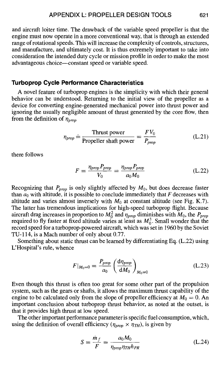
Turboprop Cycle Performance Characteristics
A novel feature of turboprop engines is the simplicity with which their general
behavior can be understood. Returning to the initial view of the propeller as a
device for converting engine-generated mechanical power into thrust power and
ignoring the usually negligible amount of thrust generated by the core flow, then
from the definition of
T/pro p
Thrust power F Vo
T/prop "z-
Propeller shaft power
Pprop
(L.21)
there follows
F -- T/prop Pprop -- l'lprop eprop
(L.22)
Vo aoMo
Recognizing that
Pprop
is only slightly affected by M0, but does decrease faster
than a0 with altitude, it is possible to conclude immediately that F decreases with
altitude and varies almost inversely with M0 at constant altitude (see Fig. K.7).
The latter has tremendous implications for high-speed turboprop flight. Because
aircraft drag increases in proportion to M E and
T/prop
diminishes with M0, the
Pprop
required to fly faster at fixed altitude varies at least as M 3. Small wonder that the
record speed for a turboprop-powered aircraft, which was set in 1960 by the Soviet
TU-114, is a Mach number of only about 0.77.
Something about static thrust can be learned by differentiating Eq. (L.22) using
UHospital's rule, whence
FIMo=0
Pprop ( dT/prop ~
(L.23)
= a-7- /Mo=O
Even though this thrust is often too great for some other part of the propulsion
system, such as the gears or shafts, it allows the maximum thrust capability of the
engine to be calculated only from the slope of propeller efficiency at M0 = O. An
important conclusion about turboprop thrust behavior, as noted at the outset, is
that it provides high thrust at low speed.
The other important performance parameter is specific fuel consumption, which,
using the definition of overall efficiency
(T/prop × T/TH),
is given by
S = thf =.
aoMo
(L.24)
F
T/propT/THhpR
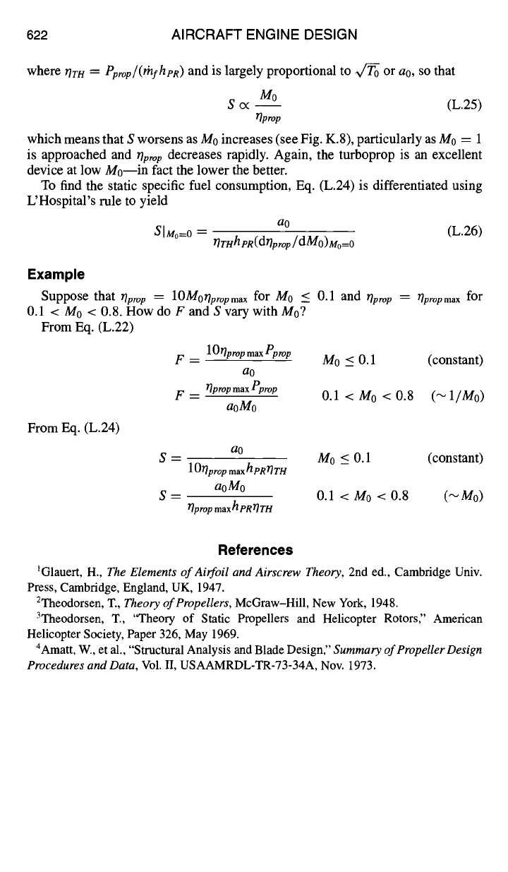
622 AIRCRAFT ENGINE DESIGN
where OrH
=
Pprop/(lhfhpR)
and is largely proportional to Vc~ or a0, so that
M0
S c< -- (L.25)
~prop
which means that S worsens as Mo increases (see Fig. K.8), particularly as Mo = 1
is approached and
Oprop
decreases rapidly. Again, the turboprop is an excellent
device at low Mo--in fact the lower the better.
To find the static specific fuel consumption, Eq. (L.24) is differentiated using
L'Hospital's rule to yield
a0
SIMo=0 =
rlrHhpR(d~prop/dMO)Mo= 0
(L.26)
Example
Suppose that
~prop
0.1 < M0 < 0.8. How do F and S vary with Mo?
From Eq. (L.22)
F
= lO~lpropmaxPprop
ao
F
-- ~prop
max
Pprop
aoMo
From Eq. (L.24)
= lOMoOpropma x
for M0 _< 0.1 and
Oprop
= Opropmax for
M0 < 0.1 (constant)
0.1 < Mo < 0.8 (~l/Mo)
a0
S = M0 < 0.1 (constant)
10ITpro
p
max
hpRrlTH
aoMo
S = 0.1 < Mo < 0.8 (~M0)
Oprop max h pR lTTH
References
IGlauert, H.,
The Elements of Airfoil and Airscrew Theory,
2nd ed., Cambridge Univ.
Press, Cambridge, England, UK, 1947.
2Theodorsen, T.,
Theory of Propellers,
McGraw-Hill, New York, 1948.
3Theodorsen, T., "Theory of Static Propellers and Helicopter Rotors," American
Helicopter Society, Paper 326, May 1969.
4Amatt, W., et al., "Structural Analysis and Blade Design,"
Summary of Propeller Design
Procedures and Data,
Vol. II, USAAMRDL-TR-73-34A, Nov. 1973.