Linden D., Reddy T.B. (eds.) Handbook of batteries
Подождите немного. Документ загружается.

NICKEL-HYDROGEN BATTERIES 32.3
the cell reversal mode without pressure buildup or net change in electrolyte concentration.
This is a unique feature of the system.
32.2.4 Self-Discharge
The electrode stack is surrounded by hydrogen under pressure. A salient feature is that the
hydrogen reacts electrochemically but not chemically to reduce the nickel oxyhydroxide.
Actually, the nickel oxyhydroxide is reduced chemically, but at such an extremely low rate
that performance for aerospace applications is not affected.
32.3 CELL AND ELECTRODE-STACK COMPONENTS
Ni-H
2
cell stacks are assembled in three distinct configurations. These include the COMSAT
back-to-back, the Air Force recirculating and the hybrid, Mantech back-to-back designs. This
section describes the electrode-stack components used for the fabrication of aerospace Ni-
H
2
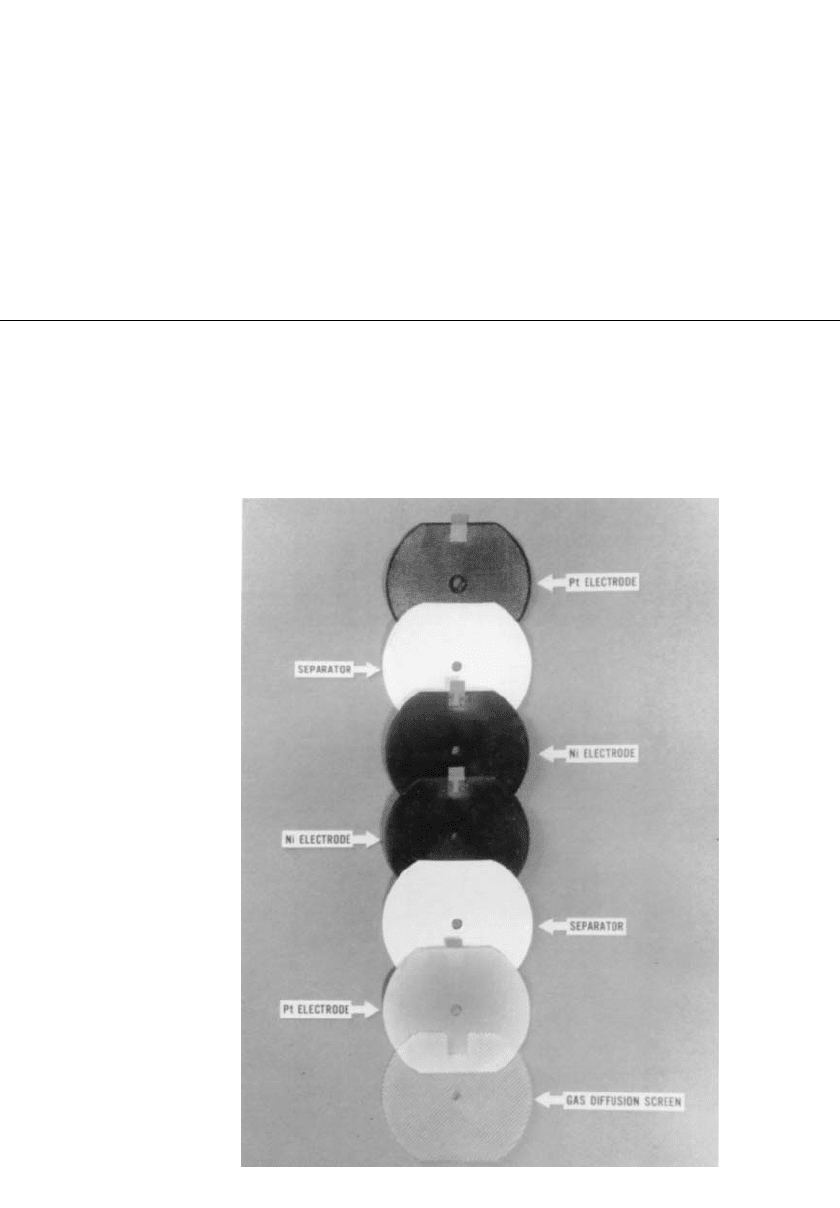
cells in these configurations. Figure 32.1 shows the truncated disk electrode-stack com-
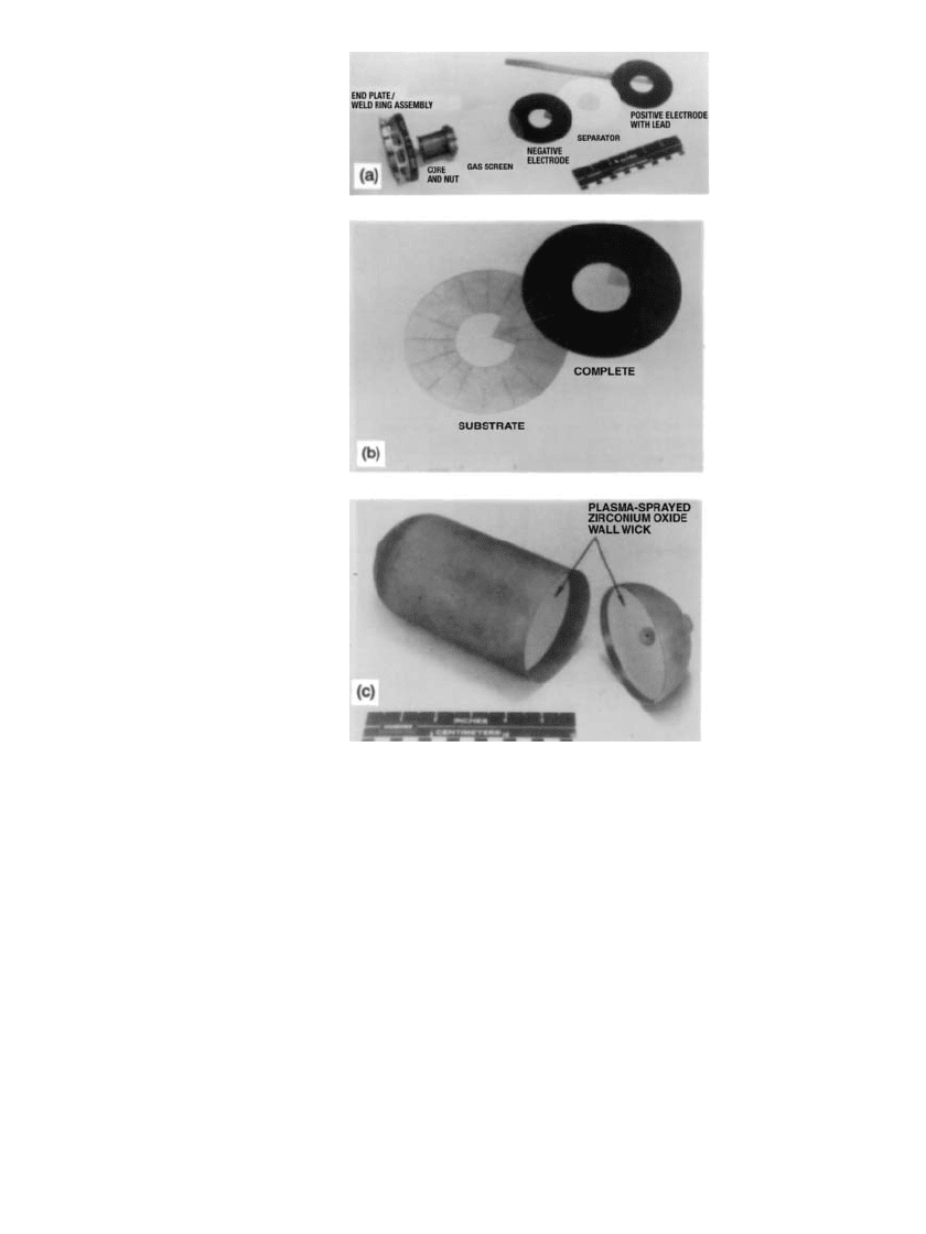
ponents used in the COMSAT design. Figure 32.2a and b shows the circular components
for the Air Force recirculating and hybrid, Mantech back-to-back designs.
FIGURE 32.1 COMSAT bus-bar-configuration electrode-stack compo-
nents.
32.4 CHAPTER THIRTY-TWO
FIGURE 32.2 Air Force pineapple-slice config-
uration: (a) Stack components. (b) Negative elec-
trode. (c) Pressure-vessel cylinder and dome.
32.3.1 Positive Electrodes (Sintered)
The sintered positive electrode consists of a sintered porous nickel plaque that is impregnated
with nickel hydroxide active material. The porous sintered plaque serves to retain the active
nickel hydroxide material within its pores and to conduct the electric current to and from
the active material. Essential features of the sintered plaque are high porosity, large surface
area, and electrical conductivity in combination with good mechanical strength.
2
Active material is impregnated into the sintered plaque by an electrochemical impreg-
nation process. There are two electrochemical impregnation processes used—aqueous and
alcoholic. The aqueous impregnation process (Bell Laboratories process)
3
uses an aqueous-
based nickel nitrate solution for the impregnation bath. The alcoholic impregnation process
(Air Force process)
4
uses an alcohol-based nickel nitrate solution for the impregnation bath.
Both processes provide the following advantages:
1. Loading of active material: Electrochemical impregnation gives very uniform loading of
the active material within the pores of the nickel sinter.

NICKEL-HYDROGEN BATTERIES 32.5
2. Loading level: The loading level of active material can be accurately controlled by the
electrochemical impregnation process. Typical loading values are
1.67
Ⳳ 0.1 g/cm
3
void volume for GEO applications
1.65
Ⳳ 0.1 g/cm
3
void volume for LEO applications
32.3.2 Hydrogen Electrode
The hydrogen electrodes consist of a Teflon-bonded platinum black catalyst supported on a
photo-etched nickel substrate with Teflon bonding. The sintered Teflon-bonded platinum
electrodes were originally developed at Tyco Laboratories for the fuel-cell industry.
5
For Ni-
H
2
cells, a hydrophobic Teflon backing was added to these platinum electrodes to stop water
or electrolyte loss from the back side of the negative platinum electrode during charge and
overcharge while readily allowing diffusion of hydrogen and oxygen gas. The use of Gortex
威
as the microporous Teflon membrane resulted from a development contract with HAC
(Hughes Aircraft Corporation).
6
The platinum content is normally specified as 7.0 Ⳳ 1.0
mg/cm
2
. The physical properties of this hydrogen electrode provide the right interface for
the electrochemical reactions to occur without flooding or drying out the electrode at the
separator interface.
32.3.3 Separator Materials
Two types of separator materials are being used for aerospace Ni-H
2
cells, (1) asbestos (fuel-
cell-grade asbestos paper) and (2) Zircar (untreated knit ZYK-15 Zircar cloth).
Fuel-cell-grade asbestos is a nonwoven fabric with a thickness of 10 to 15 mil. The
asbestos fibers are made into a long roll of nonwoven cloth by a paper-making process. As
an added precaution, the asbestos can be reconstituted in a blender and then reformed into
a cloth to avoid any nonuniformity in the original structure that would allow oxygen to
bubble through. The fuel-cell-grade asbestos has a high bubble pressure for oxygen gas; a
pressure difference of more than 1.7
⫻ 10
5
Pa is required across the separator cloth (250
m thick) to force oxygen bubbles through the material. During overcharge, oxygen gas is
forced off the backside of the positive electrode. The oxygen cannot channel or bubble
through the separator to cause rapid recombination at the negative electrode.
Zicar fibrous ceramic separators are available in textile product forms (Zircar Products,
Inc.). These textiles are composed of zirconia fibers stabilized with yttria. These materials
offer the extreme temperature and chemical resistance of the ceramic zirconia. They are
constructed of essentially continuous individual filaments fabricated in flexible textile forms.
Even with the fibrous structure, the inherently brittle nature of the ceramic material zirconia
makes these separators fragile and susceptible to breaking. They must be handled with care.
Untreated knit ZYK-15 Zircar cloth material is the tensile form used for Ni-H
2
cells.
7
Either
one of two 250 to 380
m-thick layers of this separator material can be used. The second
ZYK-15 layer is normally used as a backup to prevent oxygen channeling in the event of
assembly damage to the first layer. The knit Zircar cloth has a very low oxygen bubble-
through pressure, and during charge and overcharge, oxygen gas readily permeates through
the separator to recombine at the hydrogen platinum electrode to form water.
Both the asbestos and the Zircar separators serve the following functions:
1. They act as separators between positive and negative electrodes.
2. They serve as reservoirs for KOH electrolyte and remain stable in the electrolyte, allowing
long-term storage and cycling.
3. They serve as media for charge and discharge current through the separator via ionic
conduction of hydroxyl ions in the electrolyte.
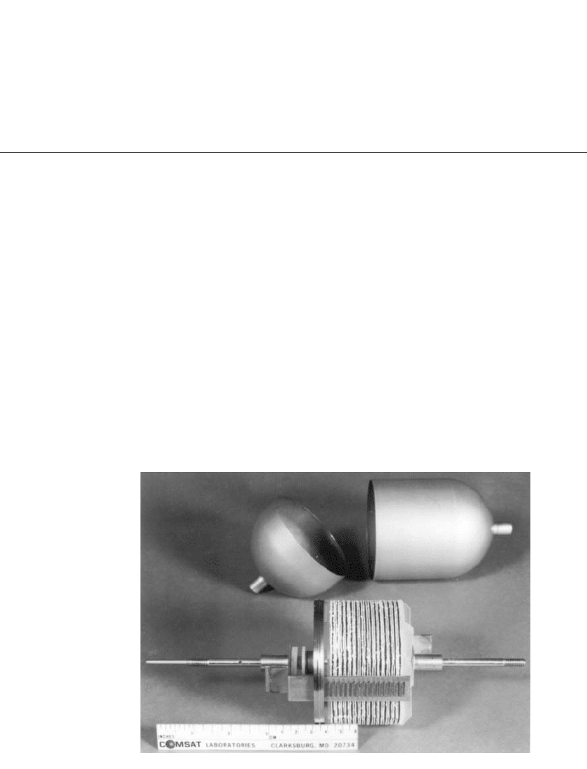
32.6 CHAPTER THIRTY-TWO
FIGURE 32.3 COMSAT NTS-2 Ni-H
2
cell components.
32.3.4 Gas Screen
A polypropylene gas diffusion screen is placed behind the hydrogen electrode to allow
hydrogen gas and oxygen gas to diffuse to the back side of the negative electrode with the
Teflon backing.
32.4 Ni-H
2
CELL CONSTRUCTION
Sealed Ni-H
2
cells contain hydrogen gas under pressure within a cylindrical pressure vessel
(see Fig. 32.2c). They are referred to as individual-pressure-vessel (IPV) cells because each
individual cell is contained within its own pressure vessel. IPV cells are assembled using
either single or dual electrode stack configurations inside the pressure vessel. An extension
of IPV is the two cell (2.5 V) CPV design made by connecting the dual electrode stacks in
series within a single pressure vessel. IPV designs include cells having diameters of 6.35,
8.89, 11.43 and 13.97 centimeters.
Descriptions of the various cell designs follow. These designs represent the first generation
of Ni-H
2
cell technology, which was developed in the 1970s and utilized in the 1980s along
with the baseline designs currently in use.
32.4.1 COMSAT Ni-H
2
Cell
Components of the COMSAT NTS-2 Ni-H
2
cell are shown in Fig. 32.3 with the electrode-
stack assembly and weld ring positioned in front of the pressure shells.
8,9
These cells were
built by Eagle-Picher Industries (EPI) under an INTELSAT/COMSAT licensing agreement.
The U.S. Navy’s Navigation Technology Satellite-2 (NTS-2), launched on June 23, 1977,
was the first flight demonstration of the Ni-H
2
battery.

NICKEL-HYDROGEN BATTERIES 32.7
Electrode Stack. Figure 32.1 shows the basic arrangement of the electrode-stack compo-
nents for the COMSAT back-to-back design. Two positive nickel oxide electrodes are po-
sitioned back-to-back. A separator is placed on each side of the positive electrodes. The
negative platinum electrodes are placed with the platinum black surface next to the separator
material. A plastic diffusion screen is placed on the back side of each negative electrode to
facilitate gas diffusion to the back side of this electrode. These components constitute one
module of the electrode stack. This arrangement is repeated until the number of modules is
reached to provide the required capacity. A complete stack can be seen in Fig. 32.3. The
bus bars for the positive and negative electrodes are located along the outside of the electrode
stack.
During charge and overcharge, oxygen gas that evolves at the nickel electrodes is forced
out between the back-to-back positive electrodes. The oxygen diffuses into the gas space
between the electrode stack and the pressure vessel wall into the region of the gas diffusion
screens on the back of the negative electrode, and through the porous backing of the negative
electrode, where it combines with hydrogen to form water. The partial pressure of oxygen
is dependent on this diffusion process. The limiting step is the oxygen diffusion in the gas-
phase pores of the Teflon-bonded electrode, not in the Teflon backing.
6
The fraction of
oxygen gas should be less than 0.5% in the surrounding hydrogen gas when the cell is
continuously overcharged at a C/2 rate.
Pressure Vessel. The pressure vessel (dome and cylinder), terminal bosses and weld rings
are all fabricated from Inconel alloy 718. The weld ring is manufactured by one of two
methods. The first is manufactured using an investment casting process and is then machined
to final dimensions. The second is manufactured by machining to final dimensions from an
extruded or wrought Inconel metal. The outside diameter of the weld ring is machined as a
T section to position the pressure shells on the weld ring and provide a backup support for
an electron beam girth weld. The Inconel 718 pressure vessel shells are manufactured to a
near uniform thickness using either a hydroforming or drawn process and then cut to length.
The thickness is determined by the operating pressure and cycle requirements for the par-
ticular use. The pressure shells are ‘‘age hardened’’ using a standard heat treatment process.
The terminal bosses for the compression seals are machined from Inconel 718 material and
electron beam welded into the domes of the pressure vessel shells. Nylon plastic is injection
molded into these barrels. The Ziegler compression seal
10
is made by crimping the bosses.
Cell designs commonly operate under maximum operating pressures between 4.1
⫻ 10
6
Pa
and 8.3
⫻ 10
6
Pa. Depending on the particular use, the vessels are designed to provide a
safety factor between 2:1 to over 4:1.
32.4.2 Air Force Ni-H
2
Cell
Typical components for the Air Force NiH
2
cell are shown in Fig. 32.2 including the elec-
trode stack components, the negative electrodes with the chem-milled substrate, and the
pressure vessel cylinder and dome with the plasma sprayed zirconium oxide wall wick for
the electrolyte. These components are typically assembled in one of two configurations.
Separators used in these designs are asbestos and Zircar alone or in combination with each
other.
The first is commonly referred to as the recirculating electrode stack design. It is made
of a number of modules comprised of a gas screen, hydrogen electrode (negative), separa-
tor(s), and nickel electrode. The capacity of the cell is determined by the number of modules
used to assemble the stack. A single gas screen and hydrogen electrode is used as the final
module to maintain a hydrogen electrode for recombination on both sides of the positive
throughout the stack. A wall wick is used on the interior of the pressure vessel to return
electrolyte to the stack, hence the name recirculating design.

32.8 CHAPTER THIRTY-TWO
In this design using asbestos or a combination of asbestos and Zircar separators, the
oxygen generated on overcharge diffuses off the back of the nickel electrode. The diffusion
path is very short; the oxygen gas simply travels through the gas screen to recombine at the
next hydrogen electrode. Oxygen comes off the back side of the positive electrode of one
module and recombines to form water at the next module. During overcharge, this transfer
of water to the next module occurs throughout the electrode stack. The last module in the
stack is simply a negative electrode and separator reservoir. The water formed at this elec-
trode-separator combination goes to the wall wick and recirculated back to balance the
electrolyte throughout the stack. With this recirculating design, the oxygen concentration is
kept very low (below 0.2% in the surrounding hydrogen gas) during continuous overcharge
at the C rate.
The second configuration is the Air Force Mantech back-to-back design. It is made in
the same manner as the COMSAT design. A separator is placed on each side of the positive
electrodes. The negative platinum electrodes are placed with the platinum black surface next
to the separator material. A plastic diffusion screen is placed on the back side of each
negative electrode to facilitate gas diffusion to the back side of this electrode. These com-
ponents constitute one module of the electrode stack. This arrangement is repeated until the
number of modules is reached to provide the required capacity. This design also uses the
wall wick for return of electrolyte to the stack.
Designs using Zircar alone normally extend the separator to the pressure vessel wall. The
Zircar contains large enough pores for oxygen gas to permeate through the pores of this
separator to the negative electrode, where it recombines to form water. Oxygen can, of
course, also emerge off the back side of the nickel electrode and diffuse through the gas
screens as before. However, most of the oxygen permeates through the separator and there
is little or no recirculation of water in cells with Zircar separators. For this design, the
concentration of oxygen in the surrounding hydrogen gas is negligible.
The electrode-stack components are shaped like a pineapple slice (see Fig. 32.2b) with
provisions for the tab in the center hole. These electrode-stack components are assembled
onto a polysulfone central core (see Fig. 32.2a). The electrode tabs are brought out through
this central core. The positive and negative tabs can be in opposite directions or in the same
direction depending on the terminal configuration. This center core serves to align the elec-
trode-stack components, provide a conduit for the positive and negative tabs, and insulate
the positive and negative tabs from each other and from the electrode-stack components.
The cell capacity in a particular diameter is limited by the ability to manufacture a
pressure vessel of sufficient length. In designing cells of larger capacity without increasing
the diameter of the pressure vessel, two approaches are used. The first involves the use of a
dual stack design to increase the capacities of cells for the individual cell diameters.
15
This
is accomplished by using two stacks assembled on a single core as described above. The
two stacks are separated by end plates and a weld ring and are connected electrically in
parallel to attain a 1.25 volt cell. The second approach utilizes a three piece pressure vessel
assembly.
16
A single electrode-stack is made with weld rings at each end. A cylinder is
placed over the stack and joined at each end with the weld rings and two dome assemblies.
Heat transfer is better with the pineapple-slice configurations than with the COMSAT
back-to-back configuration. Heat is transferred uniformly from the entire circumference of
the pineapple-slice electrodes, whereas sections are removed from the circumference of the
COMSAT back-to-back electrodes.
Pressure Vessel. The pressure vessels used for the Air Force designs are essentially the
same as those for the COMSAT designs. Certain designs utilize chemical milling to remove
material from lower stress areas for weight reduction. Typically the weld areas are not re-
duced to compensate for the strength reduction of the age hardened, Inconel 718 material in
the heat-affected zone of the weld areas. The chemical milling is done prior to heat treating
(age hardening) of the pressure vessel. The operating pressures and design margins are
similar to those discussed for the COMSAT designs.

NICKEL-HYDROGEN BATTERIES 32.9
Two terminal designs have been used. One involves the terminal design using the com-
pression seal described for the COMSAT designs. The second utilizes a hydraulic seal design.
When this is used, the seal area is hydroformed as an integral part of the dome and cylinder.
The terminal seals are hydraulic cold-flow Teflon seals.
14
Electrolyte Management. There are three mechanisms for the loss of electrolyte from the
electrode stack: (1) by entrainment in the hydrogen and oxygen gases evolved during charge
and overcharge, (2) by weeping of the negative electrode, and (3) by electrolyte displacement,
that is, the electrolyte being pressed out of the positive electrodes in the cell stack by oxygen
gas evolved during charge and overcharge.
Electrolyte loss by both entrainment and weeping of the negative electrode was deter-
mined to be negligible for negative electrodes with Gortex backing for both back-to-back
and recirculating electrode-stack configurations. The major electrolyte loss mechanism is by
displacement. When electrolyte is added to the cell, the void volume of the positive electrode
is completely saturated with electrolyte. During activation, approximately 25% of the elec-
trolyte in the positive electrodes is displaced by oxygen gas during charge and overcharge
of the cell.
6
It was found that electrolyte loss by displacement occurred during initial cycling
(activation) but eventually decreased to zero, leaving enough electrolyte to operate the cell
efficiently.
11,12
Water Loss. Water loss from the electrode stack can result from evaporation and conden-
sation of water vapor from the cell stack to the pressure-vessel wall when a large enough
temperature difference exists between stack and wall (approximately 10
⬚C difference). The
plasma-sprayed zirconium oxide wall wick
13
shown in Fig. 32.2c provides a return path for
any water loss from the cell stack independent of the mechanism.
32.4.3 Specific Energy and Energy Density
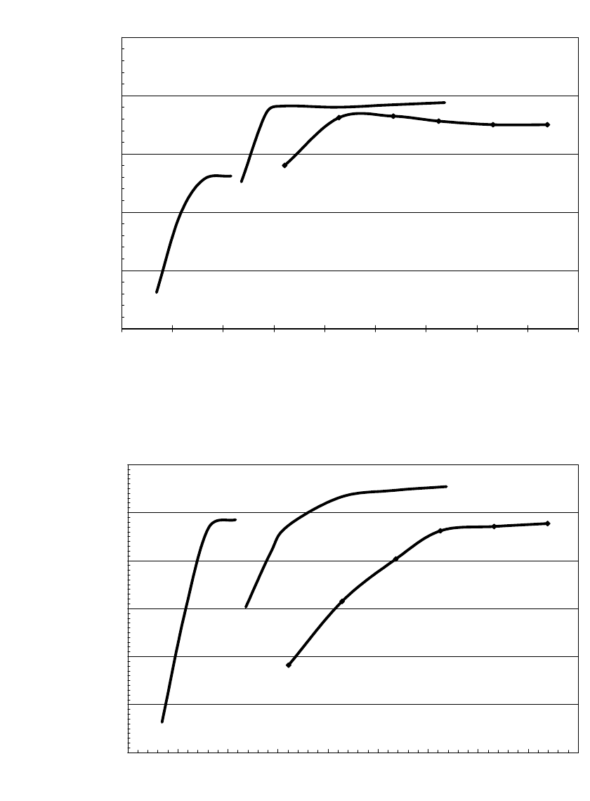
Figures 32.4 and 32.5 depict the specific energy and energy density that could be projected
for the different nickel-hydrogen cell designs. The actual values may vary depending on
manufacturer.
1. In general, the specific energy increases as the capacity increases.
2. The choice and number of separators affect the weight (quantity of electrolyte) and thus
the specific energy of the cell.
3. The energy density is primarily a function of the pressure range or free volume in the
cell. Cells operating at higher maximum operating pressures have higher energy densities.
This increase is a result of the reduction in weight of the pressure vessel at the higher
pressures.
32.10 CHAPTER THIRTY-TWO
45
50
55
60
65
70
0 50 100 150 200 250 300 350 400 450
Capacity (Ah)
Specific Energy (Wh/kg)
3.5 inch
4.5 inch
5.5 inch
FIGURE 32.4 Specific energy of Ni-H
2
cells.
50
60
70
80
90
100
110
0 50 100 150 200 250 300 350 400 450
Capacity (Ah)
Energy Density (Wh/liter)
3.5 inch
4.5 inch
5.5 inch
FIGURE 32.5 Energy density of Ni-H
2
cells.
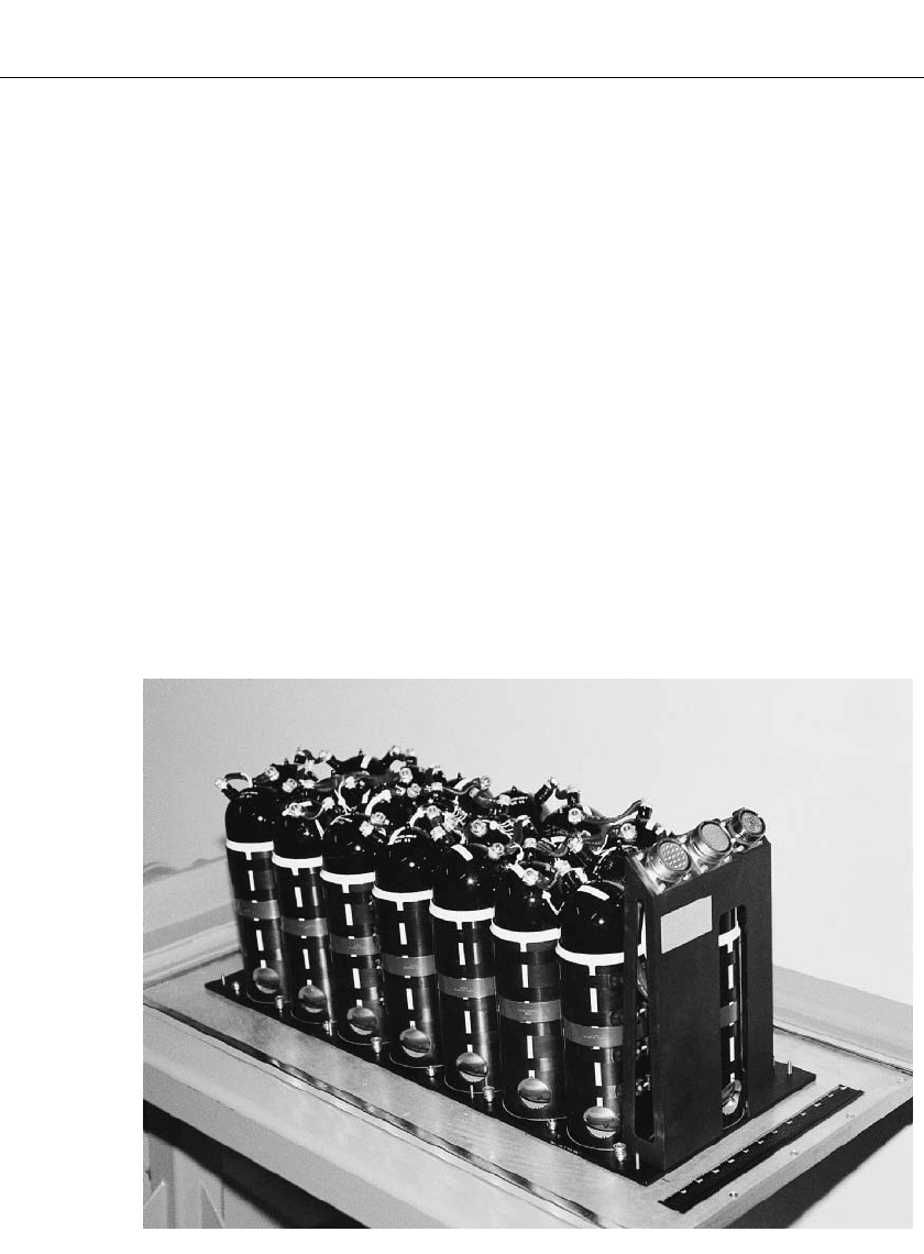
NICKEL-HYDROGEN BATTERIES 32.11
FIGURE 32.6 DMPS 100-Ah Ni-H
2
battery assembly.
32.5 Ni-H
2
BATTERY DESIGN
Various Ni-H
2
battery designs have evolved through the years. They are tailored to the
specific application and interface with the particular satellite. Mechanical and thermal re-
quirements are the primary drivers for the configuration and interface of each battery. The
nickel-hydrogen system is sensitive to temperature and performs best between
⫺10⬚C and
⫹10⬚C. Thus, thermal control of the battery is important to minimize size and weight.
Several features have been integrated into the battery designs which enhance the perform-
ance and reliability. These include: pressure monitoring of cells through strain gage or trans-
ducers, strain gage voltage amplification circuits, individual cell voltage monitors, temper-
ature monitoring, redundant individual cell heaters, and individual cell diode bypass
protection. Bypass diodes on each cell protect the battery against a failure from an open-
circuited cell. Protection in the charge direction is provided by three silicon diodes in series,
while protection in the discharge direction is provided by one Schottky barrier diode. The
diodes are mounted on heat sinks on the thermal sleeves near the base of the cells or on a
separate panel attached to the battery base plate.
Several different battery configurations can be seen in Figs. 32.6, 32.7, 32.8, 32.9 and
32.10. One of the earliest Ni-H
2
battery designs was flown on the INTELSAT V program.
Two 27-cell, 30 Ah Ni-H
2
batteries were used to provide the electric energy during launch,
transfer orbit and solar eclipses.
17
The first battery using the dual electrode stack configuration was made by Eagle-Picher
Technologies, LLC for the EUTELSAT II Program. The first of two flight sets was delivered
in February 1990 and launched in August 1990.
18
This battery is shown in Fig. 32.7.
The photovoltaic power subsystem for the International Space Station will use Ni-H
2
batteries for energy storage to support eclipse and contingency operations. These batteries
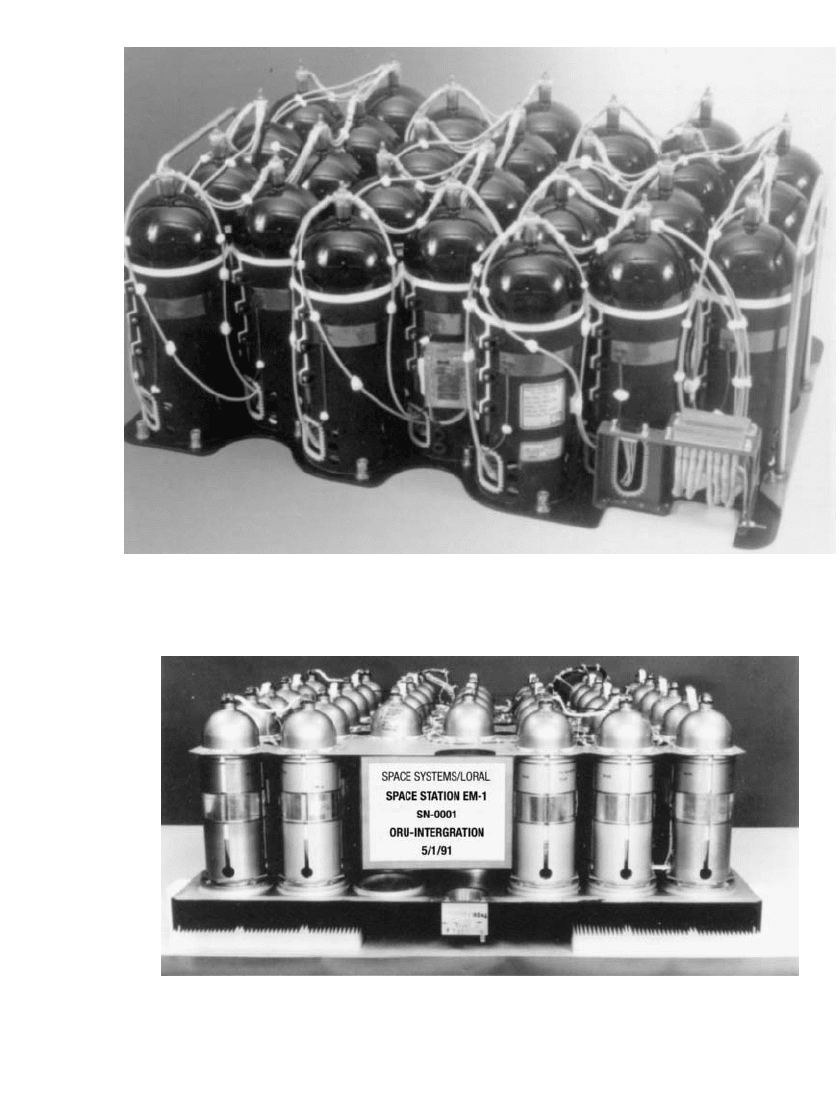
32.12 CHAPTER THIRTY-TWO
FIGURE 32.7 EUTELSAT II 58-Ah Ni-H
2
battery.
FIGURE 32.8 International Space Station 81-Ah Ni-H
2
38-cell assembly.
