Lewis R.I. Turbomachinery Performance Analysis
Подождите немного. Документ загружается.

264
Selected supporting fluid dynamic analysis
of Chapter 2. In real applications, however, it is hardly practicable to specify the
vector mean flow (W~,/3~). Let us consider instead the solution of the more realistic
direct
problem in which the cascade geometry is already fully specified and we wish
to predict its fluid-dynamic behaviour for a prescribed inflow (W1,/31).
From Fig. 9.15, making use also of Eqn (9.37), the upstream and downstream
velocities in the y direction are thus
F
Fu Fv
V1-- Voo q--~ = Voo+ Uoo-~ "+" Voo
2t
F
Fu Fv
V2= V~176 2t= V~176176176 -V~176 2t
(9.41)
Since
U 1 -- U 2 : Uoo,
dividing this equation throughout by Uoo results in
Fu Fv
tan
fll =
tan fl~ + -~- + -~-
tan/3oo
tan
f12 -"
tan/3oo Fu Fv
2t 2t tan/3oo
(9.42)
Adding these equations results in the expression for /3oo derived in Chapter 2,
namely
tan/3oo = X(tan
fll "}"
tan/32)
(2.1)
Subtracting Eqns (9.42) and using the last expression to eliminate /3oo results
finally in
[(aFv,2/) (2 )ru]
/32 = arc tan 1 + Fv/2t tan
fll-
1 + Fv/2t --~ (9.43)
Thus for any chosen inlet angle
ill,
the outlet angle/32 is immediately calculable from
the two unit solutions which deliver the unique values of Fu and Fv, Eqns (9.35),
derived in the previous section for the single aerofoil but equally applicable for the
cascade.
9.4.2 Shock-free inflow conditions
As already discussed in Section 2.6 and illustrated by Fig. 9.16, shock-free inflow
is the fluid-dynamic ideal to achieve minimum profile losses. The stagnation point
will then be located directly on the leading edge of the profile. By analogy with the
Kutta-Joukowski trailing edge condition, Section 9.3.3, smooth leading edge flow
will occur when the surface velocities Vs on elements 1 and M closest to the leading
edge are equal and opposite (remembering the convention that Vs is +ve when
clockwise). Thus, by analogy with Eqn (9.30), for shock-free inflow we will have
VSI=--VsM
or
"Y(S1)=--'Y(SM)
(9.44)
9.5 Axisymmetric bodies, ducts and ducted propellers
265
4
3
,,
v
Fig. 9.16
Shock-free inflow conditions
Substituting from Eqn (9.36) and rearranging, the vector mean angle for shock-free
inflow is thus
fl~SF= _ arctan ( yu(sl) + yu(sM) + Fu(yr(sl) + yr(sM)) )
~/v(Sl) + Vv(SM) + Fv(3,r(sl) +
Vr(SM))
The shock-free inflow angle then follows from Eqn (9.42a), namely
(9.45)
{Fu ( Fv)
fllSF
=
arc tan -~- + tan/30o 1 + -~ (9.46)
Example 9.3 Flow past a compressor cascade
The source code for a simple PASCAL program BLADEROW is provided on the
accompanying disc to show how the above cascade analysis can be converted into
computer code. BLADEROW receives as input
(x,y)
profile coordinate data
generated by the blade design program STACK which is stored in the file
RAWDATA. The more advanced program CASCADE performs both profile design
and flow analysis (user instructions are given in Appendix II) and also stores the raw
profile coordinates in the file RAWDATA. A comparison of predicted surface
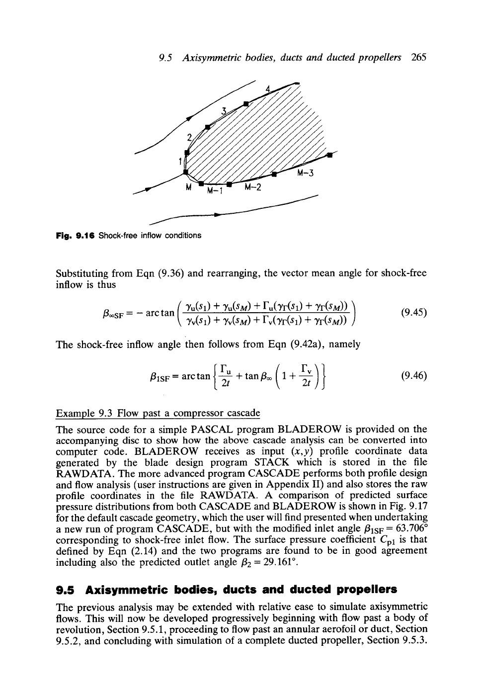
pressure distributions from both CASCADE and BLADEROW is shown in Fig. 9.17
for the default cascade geometry, which the user will find presented when undertaking
a new run of program CASCADE, but with the modified inlet angle/31SF = 63.706 ~
corresponding to shock-free inlet flow. The surface pressure coefficient Cpl is that
defined by Eqn (2.14) and the two programs are found to be in good agreement
including also the predicted outlet angle/32 = 29.161 ~
9.5 Axisymmetric bodies, ducts and ducted propellers
The previous analysis may be extended with relative ease to simulate axisymmetric
flows. This will now be developed progressively beginning with flow past a body of
revolution, Section 9.5.1, proceeding to flow past an annular aerofoil or duct, Section
9.5.2, and concluding with simulation of a complete ducted propeller, Section 9.5.3.
266
Selected supporting fluid dynamic analysis
1.~ I
0.8
0.6"
O.4
.I
'- 0. 0"2 i
o 0.0
--0.2"
-0"4 i
--0.6'
-0.8
0.0 0:s
x/I
1.0
Program CASCADE 9 Program BLADEROW
]
C4 profile
2L = 45 ~
circular arc camber 0 = 60 ~
t/l = 1.0 fll = 63-706~ (i.e. shock-free)
f12 = 29.161 o (predicted)
Fig. 9.17 Comparison of surface pressure distributions predicted by programs CASCADE and
BLADEROW for a compressor cascade designed for shock-free inflow
W~
m
v x
\
.,.
Surface ring vorticity
element
',((Sn)AS n
,/
n
Ax
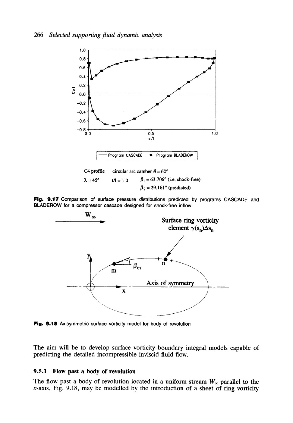
Fig. 9.18 Axisymmetric surface vorticity model for body of revolution
The aim will be to develop surface vorticity boundary integral models capable of
predicting the detailed incompressible inviscid fluid flow.
9.5.1 Flow past a body of revolution
The flow past a body of revolution located in a uniform stream Woo parallel to the
x-axis, Fig. 9.18, may be modelled by the introduction of a sheet of ring vorticity
9.5 Axisymmetric bodies, ducts and ducted propellers 267
1.6
1.4
vs/Wo.
1.2
1.0
0.8
0.6
0.4
0.2
0.0
Exact solution.
I
Pr ogr am AXISYM
o zb 4b 6o 8'0 160~ol~,o~f~olao
0
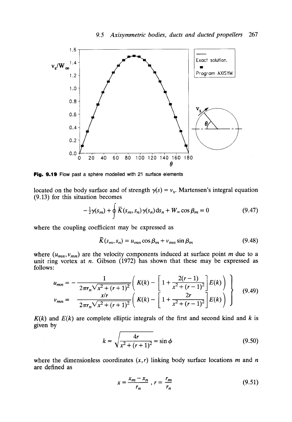
Fig. 9.19 Flow past a sphere modelled with 21 surface elements
located on the body surface and of strength y(s) = Vs. Martensen's integral equation
(9.13) for this situation becomes
-- l~l(Sm) + ~ g(Sm, Sn)'}t(Sn)dSn "at" Woo
cos tim = 0
(9.47)
J
where the coupling coefficient may be expressed as
m
g(Sm, Sn) = Umn
COS
~m Jr- 1Jmn
sin
tim
(9.48)
where
(Umn ,
Vmn ) are the velocity components induced at surface point m due to a
unit ring vortex at n. Gibson (1972) has shown that these may be expressed as
follows:
Umn = --
Vmn =
1 (
2 7rr n V'X 2 + ( r + 1) 2
x/r (
2rrrnN/X2 + (r +
1) 2
K(k)- [
K(~:)- [
1,] )
1 +
X2 q'-
(r- 1) 2 E(k)
1 + x2 + (r- 1) 2 E(k)
(9.49)
K(k) and E(k) are complete elliptic integrals of the first and second kind and k is
given by
~/x 4r
k = 2 + (r + 1) 2 = sin 4) (9.50)
where the dimensionless coordinates (x,r) linking body surface locations m and n
are defined as
Xm--Xn rm
(9.51)
X--~ , r--
rn rn
268
Selected supporting fluid dynamic analysis
i
< e ~---I
v
x
A~_is of symmet~
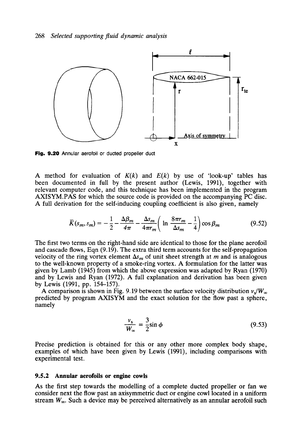
Fig. 9.20 Annular aerofoil or ducted propeller duct
rte
A method for evaluation of
K(k)
and
E(k)
by use of 'look-up' tables has
been documented in full by the present author (Lewis, 1991), together with
relevant computer code, and this technique has been implemented in the program
AXISYM.PAS for which the source code is provided on the accompanying PC disc.
A full derivation for the self-inducing coupling coefficient is also given, namely
m(,nS rm
K (Sm,
Sm) =
2 47r
47rr m
Z~S m
COS
tim (9.52)
The first two terms on the right-hand side are identical to those for the plane aerofoil
and cascade flows, Eqn (9.19). The extra third term accounts for the self-propagation
velocity of the ring vortex element/~m
Of
unit sheet strength at m and is analogous
to the well-known property of a smoke-ring vortex. A formulation for the latter was
given by Lamb (1945) from which the above expression was adapted by Ryan (1970)
and by Lewis and Ryan (1972). A full explanation and derivation has been given
by Lewis (1991, pp. 154--157).
A comparison is shown in Fig. 9.19 between the surface velocity distribution
vJW~
predicted by program AXISYM and the exact solution for the flow past a sphere,
namely
Vs
3 .
W~ = ~sm 4) (9.53)
Precise prediction is obtained for this or any other more complex body shape,
examples of which have been given by Lewis (1991), including comparisons with
experimental test.
9.5.2 Annular aerofoils or engine cowls
As the first step towards the modelling of a complete ducted propeller or fan we
consider next the flow past an axisymmetric duct or engine cowl located in a uniform
stream W~. Such a device may be perceived alternatively as an annular aerofoil such
Cp
9.5 Axisymmetric bodies, ducts and ducted propellers
269
1.0
P -P,,
W 2
0.5
S
0.0
-0.5
-1.0
o.o o.'z o14 o16 x/e o18
Theory- DUCT.PAS 9 Fxpt. 0ufer surfece 9 Expf. Inner surfece
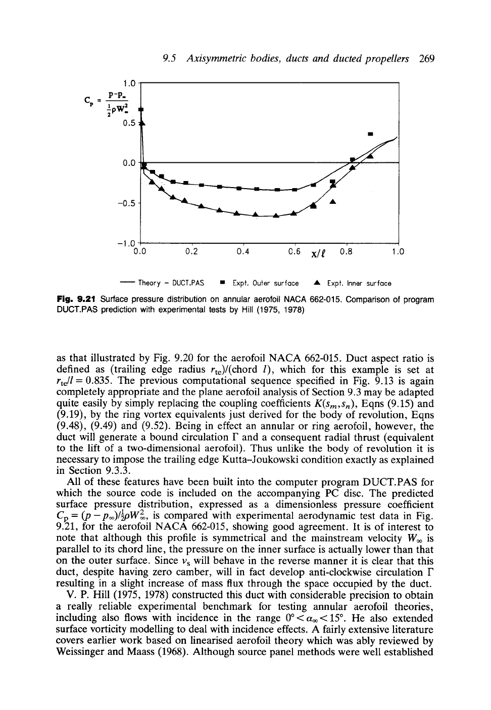
Fig, 9,21 Surface pressure distribution on annular aerofoil NACA 662-015. Comparison of program
DUCT.PAS prediction with experimental tests by Hill (1975, 1978)
as that illustrated by Fig. 9.20 for the aerofoil NACA 662-015. Duct aspect ratio is
defined as (trailing edge radius rte)/(chord l), which for this example is set at
rte/l
= 0.835. The previous computational sequence specified in Fig. 9.13 is again
completely appropriate and the plane aerofoil analysis of Section 9.3 may be adapted
quite easily by simply replacing the coupling coefficients
K(sm,Sn) ,
Eqns (9.15) and
(9.19), by the ring vortex equivalents just derived for the body of revolution, Eqns
(9.48), (9.49) and (9.52). Being in effect an annular or ring aerofoil, however, the
duct will generate a bound circulation F and a consequent radial thrust (equivalent
to the lift of a two-dimensional aerofoil). Thus unlike the body of revolution it is
necessary to impose the trailing edge Kutta-Joukowski condition exactly as explained
in Section 9.3.3.
All of these features have been built into the computer program DUCT.PAS for
which the source code is included on the accompanying PC disc. The predicted
surface pressure distribution, expressed as a dimensionless pressure coefficient
Cp "- (19- poO/~oW=,~
2 is compared with experimental aerodynamic test data in Fig.
9.21, for the aerofoil NACA 662-015, showing good agreement. It is of interest to
note that although this profile is symmetrical and the mainstream velocity Woo is
parallel to its chord line, the pressure on the inner surface is actually lower than that
on the outer surface. Since Vs will behave in the reverse manner it is clear that this
duct, despite having zero camber, will in fact develop anti-clockwise circulation F
resulting in a slight increase of mass flux through the space occupied by the duct.
V. P. Hill (1975, 1978) constructed this duct with considerable precision to obtain
a really reliable experimental benchmark for testing annular aerofoil theories,
including also flows with incidence in the range 0~ aoo < 15 ~ He also extended
surface vorticity modelling to deal with incidence effects. A fairly extensive literature
covers earlier work based on linearised aerofoil theory which was ably reviewed by
Weissinger and Maass (1968). Although source panel methods were well established
270
Selected supporting fluid dynamic analysis
in the 1960s, e.g. Smith and Hess (1966), surface vorticity modelling was still
undeveloped for duct flows until the publication by Ryan (1970) out of which the
work of Hill and others developed.
9.5.3 Ducted propellers
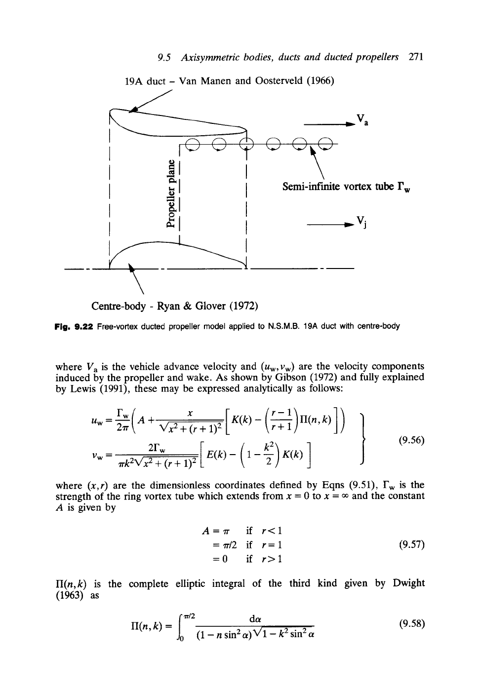
A complete ducted propeller system may be modelled in the manner illustrated in
Fig. 9.22. First of all the body of revolution and annular aerofoil solutions of Sections
9.5.1 and 9.5.2 may be combined for simulation of the propeller boss and surrounding
duct. Secondly the discontinuity across the edge of the downstream jet wake from
the jet velocity Vj to the mainstream advance velocity Va may be modelled by a
semi-infinite vortex tube Fw. Here we will consider only the free-vortex propeller and
its circumferentially averaged effect. In reality the blade bound vortices would be
shed from the blade tips as a structure of helical vortices extending downstream to
x = oo. The circumferential model of this comprises a vortex tube emanating from
the blade tips in the form of a helically spiralling vortex sheet. The tangential or 'ring'
vorticity component of this sheet, which forms a tube, is of special importance here
since it induces velocity components (Uw, Vw) due to the propeller and its infinite wake
which must be accounted for in the flow simulation model. We will return to this
matter again shortly, having first considered the overall structure of the boundary
integral equations and their consequent matrix form for simulation of this problem,
namely
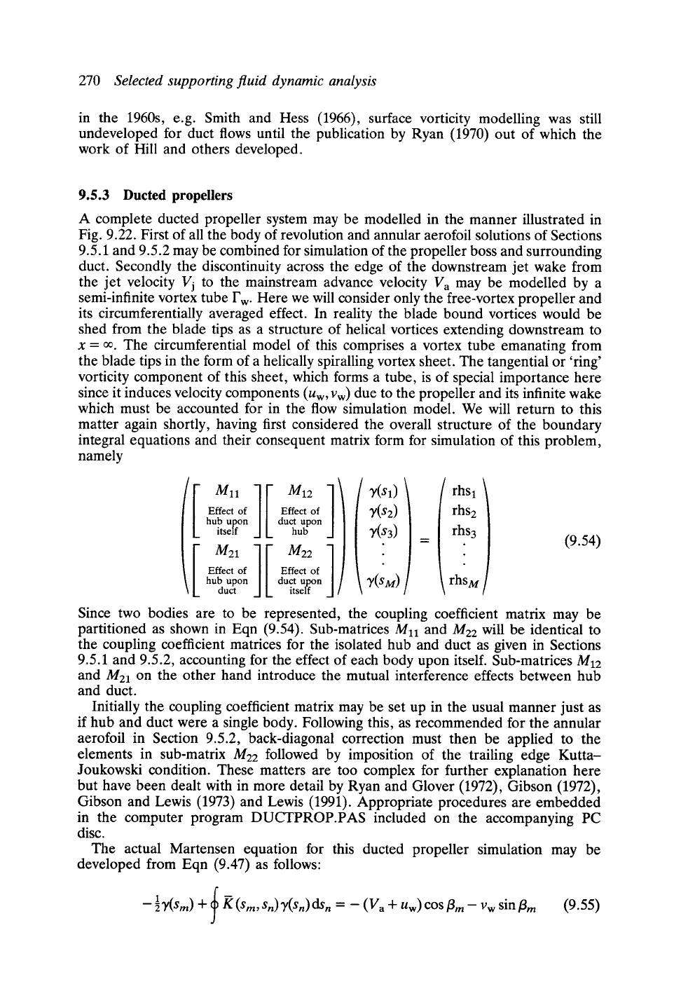
i ][ ] '
Effect of Effect of
hub upon duct upon
itself hub
[ ][ ]
Effect of Effect of
hub upon duct upon
duct itself ]
~(S1
T(S2
~'(sM
rhSl
rhs2
rhs3
rhSM
(9.54)
Since two bodies are to be represented, the coupling coefficient matrix may be
partitioned as shown in Eqn (9.54). Sub-matrices
Mll
and M22 will be identical to
the coupling coefficient matrices for the isolated hub and duct as given in Sections
9.5.1 and 9.5.2, accounting for the effect of each body upon itself. Sub-matrices M12
and M21 on the other hand introduce the mutual interference effects between hub
and duct.
Initially the coupling coefficient matrix may be set up in the usual manner just as
if hub and duct were a single body. Following this, as recommended for the annular
aerofoil in Section 9.5.2, back-diagonal correction must then be applied to the
elements in sub-matrix M22 followed by imposition of the trailing edge Kutta-
Joukowski condition. These matters are too complex for further explanation here
but have been dealt with in more detail by Ryan and Glover (1972), Gibson (1972),
Gibson and Lewis (1973) and Lewis (1991). Appropriate procedures are embedded
in the computer program DUCTPROP.PAS included on the accompanying PC
disc.
The actual Martensen equation for this ducted propeller simulation may be
developed from Eqn (9.47) as follows:
--~t(Sm) + K(sm, Sn)T(sn)ds n
= - (V a + Uw)COS~m-- VwSin/3 m
(9.55)
9.5 Axisymmetric bodies, ducts and ducted propellers
271
19A duct- Van Manen and Oosterveld (1966)
I
I - I
a
-
..V
a
v
Semi-infinite vortex
tube
r W
. vj
Centre-body - Ryan & Glover (1972)
Fig. 9.22 Free-vortex ducted propeller model applied to N.S.M.B. 19A duct with centre-body
where Va is the vehicle advance velocity and (Uw, Vw) are the velocity components
induced by the propeller and wake. As shown by Gibson (1972) and fully explained
by Lewis (1991), these may be expressed analytically as follows"
rw(
Uw = -~-~ A-t
x [K(k)-(r-1)H(n k)])
V'x2 + (r + 1)2 r+
1 '
2rw
[ E(k)_ ( l _ k__~ ) K(k) ]
Vw = ,trkEN//x2 +
(r
+
1) 2
(9.56)
where (x,r) are the dimensionless coordinates defined by Eqns (9.51), Fw is the
strength of the ring vortex tube which extends from x = 0 to x = oo and the constant
A is given by
A=~r
if r<l
=~r/2 if r=l
=0 if r>l
(9.57)
H(n,k) is the complete elliptic integral of the third kind given by Dwight
(1963) as
(
Ir/2 da
II(n, k) =
J0 (1 - n sin E a)~v/1 - k 2 sin E a
(9.58)
272
-5
-10
-15
-20
-25
Selected supporting fluid dynamic analysis
~
x ,,,:_ x x x ~< ~ ~ v
M
m
0 20
(a)
J =
0.224
40 60 80 100
x/l%
1
0
-1
-2
-3
rJ_. 4
-5
--6
-7
-8
- A
L ............ x .... x x
0 20 40 60 80 100
x/l%
(b) J = 0.36
1.0
0.0
-1.0
-2.0
-3.0
ira-
x
0 20 40 60 80 100
x/! %
(c) J = 0.551
[ -Theory,- DUCTPROP
" Inner surface -
Exp
x Outer surface -
Exp!
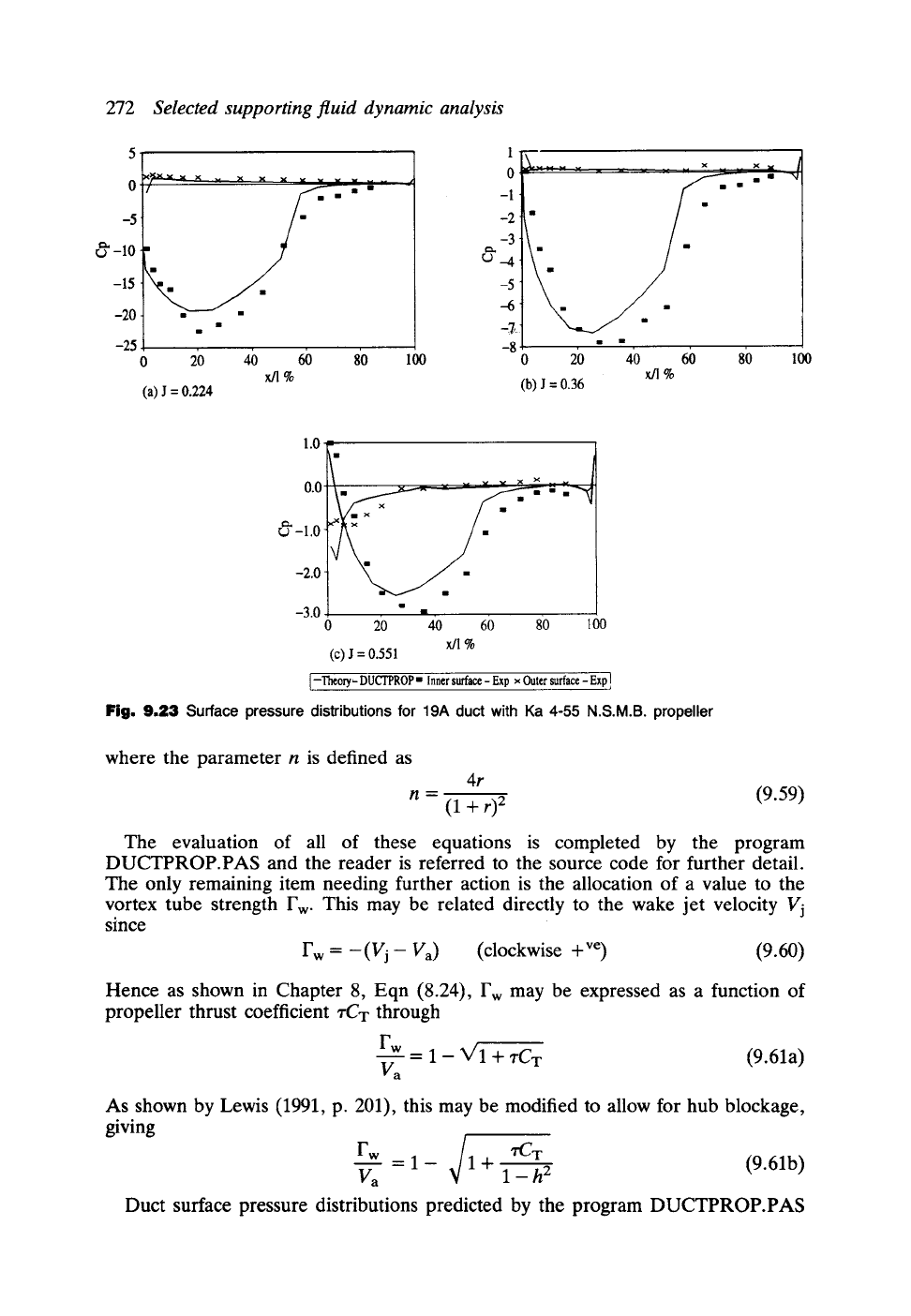
Fig. 9.23 Surface pressure distributions for 19A duct with Ka 4-55 N.S.M.B. propeller
where the parameter n is defined as
4r
n = (1 + r) 2 (9.59)
The evaluation of all of these equations is completed by the program
DUCTPROP.PAS and the reader is referred to the source code for further detail.
The only remaining item needing further action is the allocation of a value to the
vortex tube strength Fw. This may be related directly to the wake jet velocity Vj
since
Fw = -(Vj- Va) (clockwise +ve) (9.60)
Hence as shown in Chapter 8, Eqn (8.24), Fw may be expressed as a function of
propeller thrust coefficient zCT through
F...~w = 1 - V'I + "rCT
(9.61a)
Va
As shown by Lewis (1991, p. 201), this may be modified to allow for hub blockage,
giving
rw /
Va =1- ~/1+ l_h2
(9.61b)
Duct surface pressure distributions predicted by the program DUCTPROP.PAS
9.5 Axisymmetric bodies, ducts and ducted propellers
273
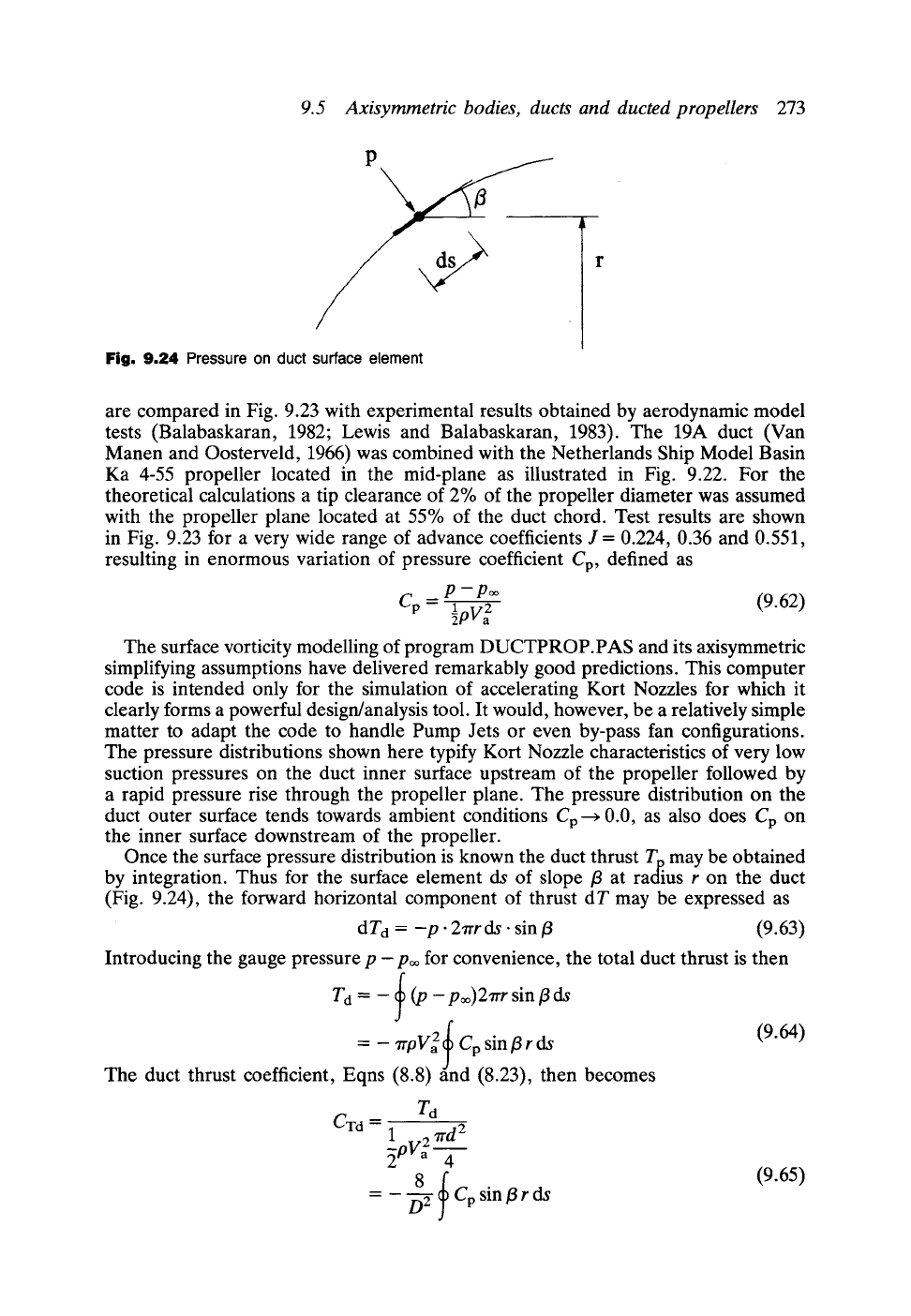
Fig. 9.24
Pressure on duct surface element
are compared in Fig. 9.23 with experimental results obtained by aerodynamic model
tests (Balabaskaran, 1982; Lewis and Balabaskaran, 1983). The 19A duct (Van
Manen and Oosterveld, 1966) was combined with the Netherlands Ship Model Basin
Ka 4-55 propeller located in the mid-plane as illustrated in Fig. 9.22. For the
theoretical calculations a tip clearance of 2% of the propeller diameter was assumed
with the propeller plane located at 55% of the duct chord. Test results are shown
in Fig. 9.23 for a very wide range of advance coefficients J = 0.224, 0.36 and 0.551,
resulting in enormous variation of pressure coefficient Cp, defined as
Cp --" P--P=1
2 (9.62)
~pv~
The surface vorticity modelling of program DUCTPROP.PAS and its axisymmetric
simplifying assumptions have delivered remarkably good predictions. This computer
code is intended only for the simulation of accelerating Kort Nozzles for which it
clearly forms a powerful design/analysis tool. It would, however, be a relatively simple
matter to adapt the code to handle Pump Jets or even by-pass fan configurations.
The pressure distributions shown here typify Kort Nozzle characteristics of very low
suction pressures on the duct inner surface upstream of the propeller followed by
a rapid pressure rise through the propeller plane. The pressure distribution on the
duct outer surface tends towards ambient conditions Cp ~ 0.0, as also does Cp on
the inner surface downstream of the propeller.
Once the surface pressure distribution is known the duct thrust Tp. may be obtained
by integration. Thus for the surface element ds of slope/3 at radius r on the duct
(Fig. 9.24), the forward horizontal component of thrust d T may be expressed as
d Td = --p" 27rr ds. sin/3
(9.63)
Introducing the gauge pressure p -p= for convenience, the total duct thrust is then
f
Td = - ~b (p - po~)27rr sin/3 ds
J
= - 7rpV 2 ~ Cp
sin/3 r ds (9.64)
!
The duct thrust coefficient, Eqns (8.8) find (8.23), then becomes
CTd -" 1 2 7rd2
~pVa 4
=---'~ Cp
sin/3 r ds
(9.65)