Lewis R.I. Turbomachinery Performance Analysis
Подождите немного. Документ загружается.

294
Appendix H
negative/~1
positive
/~1
~ positive
t
~N negative
Compressor Turbine
cascade cascade
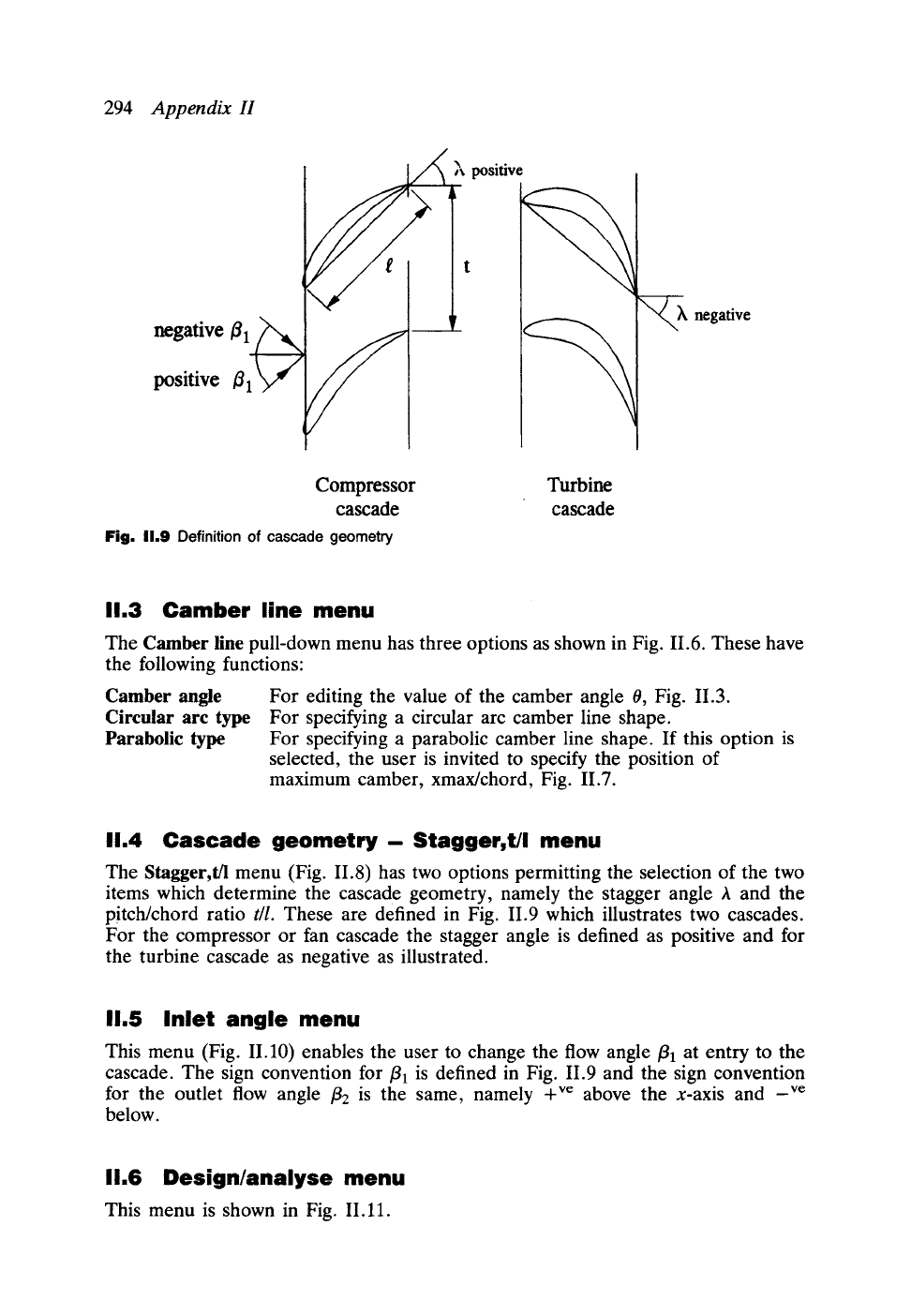
Fig. 11.9 Definition of cascade geometry
11.3 Camber line menu
The Camber line pull-down menu has three options as shown in Fig. 11.6. These have
the following functions:
Camber angle For editing the value of the camber angle 0, Fig. 11.3.
Circular
arc type
For specifying a circular arc camber line shape.
Parabolic type
For specifying a parabolic camber line shape. If this option is
selected, the user is invited to specify the position of
maximum camber, xmax/chord, Fig. II.7.
11.4 Cascade geometry- Stagger, t/I menu
The Stagger, t/l menu (Fig. 11.8) has two options permitting the selection of the two
items which determine the cascade geometry, namely the stagger angle A and the
pitch/chord ratio
t/l.
These are defined in Fig. 11.9 which illustrates two cascades.
For the compressor or fan cascade the stagger angle is defined as positive and for
the turbine cascade as negative as illustrated.
11.5 Inlet angle menu
This menu (Fig. II.10) enables the user to change the flow angle/3~ at entry to the
cascade. The sign convention for/31 is defined in Fig. 11.9 and the sign convention
for the outlet flow angle /32 is the same, namely +ve above the x-axis and _ve
below.
11.6 Design/analyse menu
This menu is shown in Fig. II.11.
11.6 Design/analysemenu
295
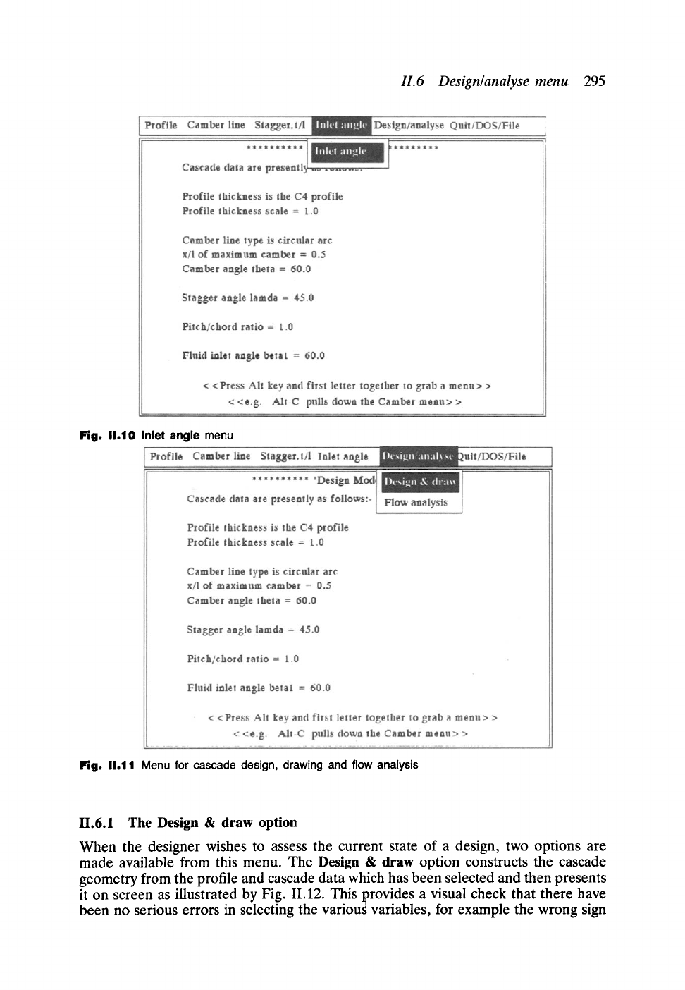
Fig. I1.10 Inlet angle menu
Fig. I1.11 Menu for cascade design, drawing and flow
analysis
11.6.1 The Design & draw option
When the designer wishes to assess the current state of a design, two options are
made available from this menu. The Design & draw option constructs the cascade
geometry from the profile and cascade data which has been selected and then presents
it on screen as illustrated by Fig. 11.12. This provides a visual check that there have
been no serious errors in selecting the variougvariables, for example the wrong sign
296
Appendix H
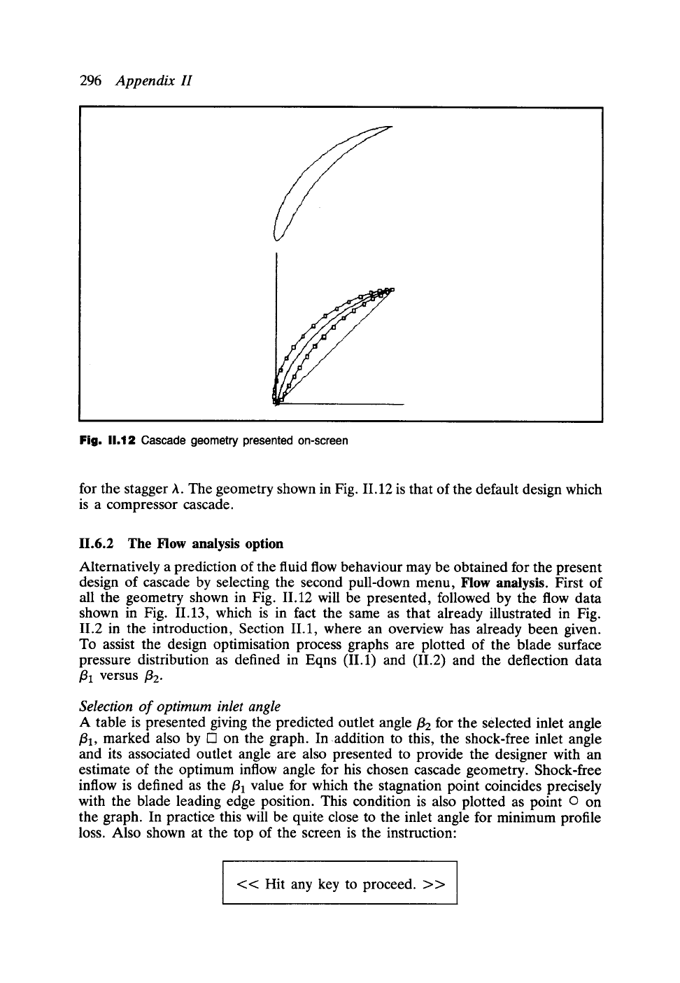
Fig. 11.12 Cascade geometry presented
on-screen
for the stagger h. The geometry shown in Fig. II. 12 is that of the default design which
is a compressor cascade.
11.6.2 The Flow analysis option
Alternatively a prediction of the fluid flow behaviour may be obtained for the present
design of cascade by selecting the second pull-down menu, Flow analysis. First of
all the geometry shown in Fig. 11.12 will be presented, followed by the flow data
shown in Fig. 11.13, which is in fact the same as that already illustrated in Fig.
11.2 in the introduction, Section II.1, where an overview has already been given.
To assist the design optimisation process graphs are plotted of the blade surface
pressure distribution as defined in Eqns (II.1) and (11.2) and the deflection data
fll
versus f12"
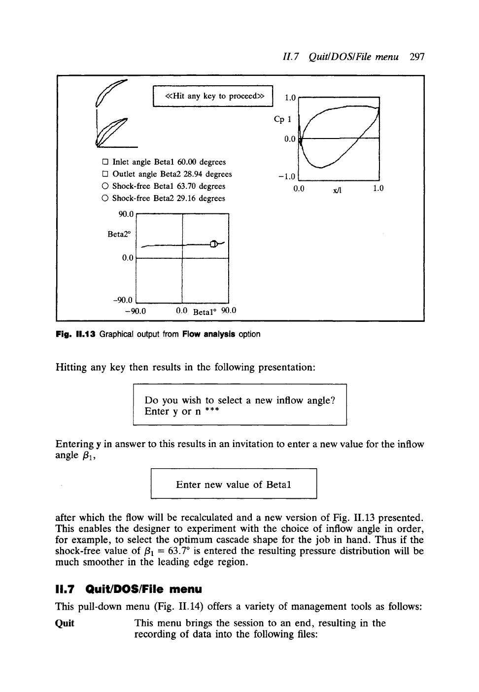
Selection of optimum inlet angle
A table is presented giving the predicted outlet angle
f12
for the selected inlet angle
/31, marked also by I-q on the graph. Inaddition to this, the shock-free inlet angle
and its associated outlet angle are also presented to provide the designer with an
estimate of the optimum inflow angle for his chosen cascade geometry. Shock-free
inflow is defined as the/31 value for which the stagnation point coincides precisely
with the blade leading edge position. This condition is also plotted as point o on
the graph. In practice this will be quite close to the inlet angle for minimum profile
loss. Also shown at the top of the screen is the instruction:
<< Hit any key to proceed. >>
H. 7 Quit~DOS~File menu 297
f
<<Hit any key to proceed>>
I
1.0
Cp 1
0.0
-1.0
0.0 x/l
l-3 Inlet angle Beta1 60.00 degrees
[--1 Outlet angle Beta2 28.94 degrees
O Shock-free Betal 63.70 degrees
O Shock-free Beta2 29.16 degrees
90.0 r
Beta2 ~
0.0
-90.0
-90.0
0.0 Betal o 90.0
Fig. 11.13 Graphical output from Flow analysis option
1.0
Hitting any key then results in the following presentation:
Do you wish to select a new inflow angle?
Enter y or n ***
Entering y in answer to this results in an invitation to enter a new value for the inflow
angle/31,
Enter new value of Beta1
after which the flow will be recalculated and a new version of Fig. 11.13 presented.
This enables the designer to experiment with the choice of inflow angle in order,
for example, to select the optimum cascade shape for the job in hand. Thus if the
shock-free value of/31 = 63.7 ~ is entered the resulting pressure distribution will be
much smoother in the leading edge region.
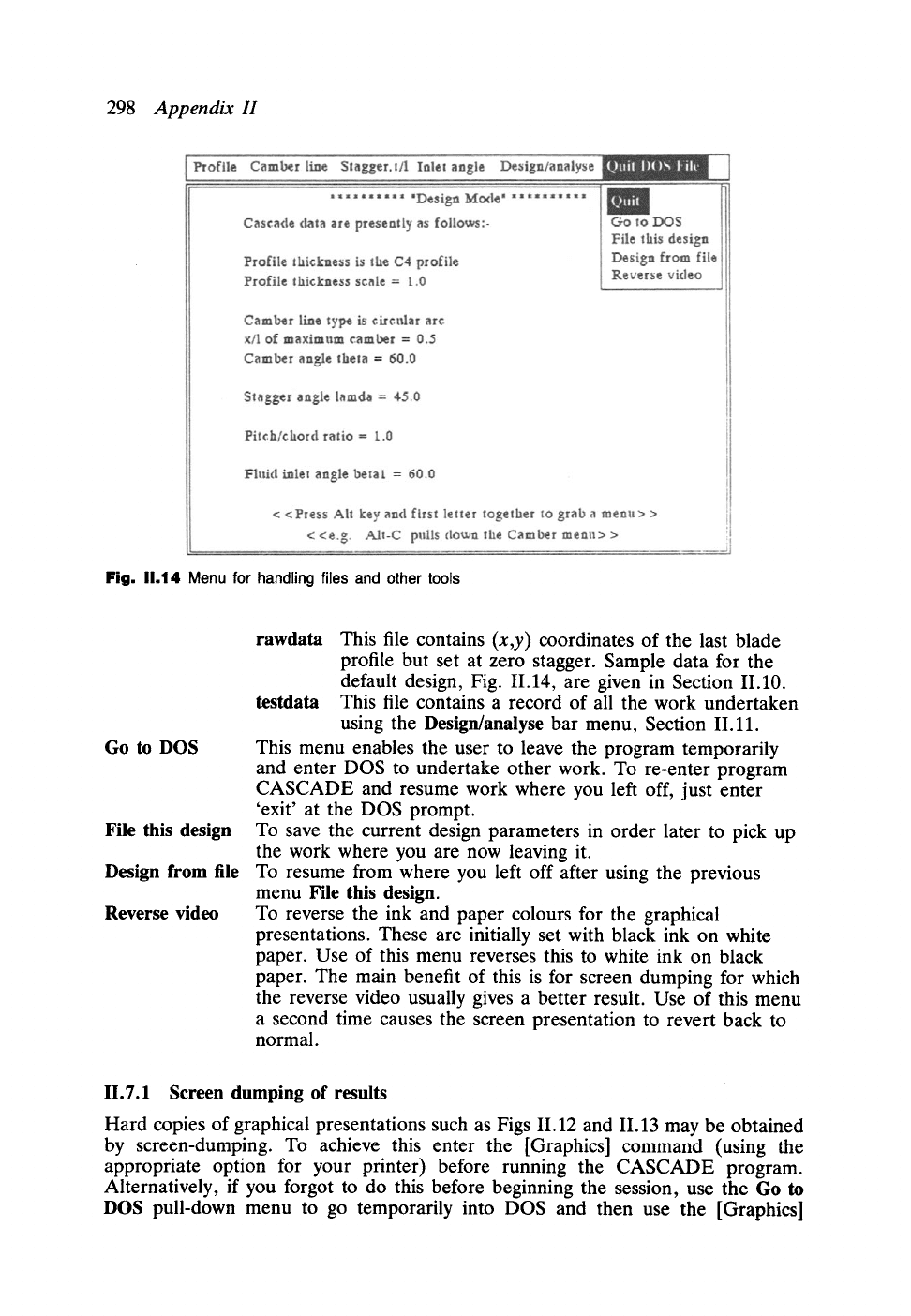
11.7 Quit/DOS/File menu
This pull-down menu (Fig. 11.14) offers a variety of management tools as follows:
Quit
This menu brings the session to an end, resulting in the
recording of data into the following files:
298
Appendix H
Fig. 11.14 Menu for handling files and other tools
Go to DOS
File this design
Design from file
Reverse video
rawdata
This file contains (x,y) coordinates of the last blade
profile but set at zero stagger. Sample data for the
default design, Fig. 11.14, are given in Section II.10.
testdata
This file contains a record of all the work undertaken
using the Design/analyse bar menu, Section II.11.
This menu enables the user to leave the program temporarily
and enter DOS to undertake other work. To re-enter program
CASCADE and resume work where you left off, just enter
'exit' at the DOS prompt.
To save the current design parameters in order later to pick up
the work where you are now leaving it.
To resume from where you left off after using the previous
menu File
this design.
To reverse the ink and paper colours for the graphical
presentations. These are initially set with black ink on white
paper. Use of this menu reverses this to white ink on black
paper. The main benefit of this is for screen dumping for which
the reverse video usually gives a better result. Use of this menu
a second time causes the screen presentation to revert back to
normal.
II.7.1 Screen dumping of results
Hard copies of graphical presentations such as Figs 11.12 and 11.13 may be obtained
by screen-dumping. To achieve this enter the [Graphics] command (using the
appropriate option for your printer) before running the CASCADE program.
Alternatively, if you forgot to do this before beginning the session, use the Go to
DOS pull-down menu to go temporarily into DOS and then use the [Graphics]
H.8 Example- design of an optimum compressor cascade
299
command before returning to CASCADE. Then press the Print Screen key whenever
you wish to dump the graphical presentations to the printer.
11.8 Example- design of an optimum compressor cascade
To illustrate the use of the program CASCADE let us consider the selection of
optimum profile geometry to meet prescribed aerodynamic requirements which are
to be as follows:
Design requirements
We will adopt the case considered in Chapter 2, Fig. 2.7, where we are given
fll ----
54.59~
f12 =
30.69~ C4 profile, circular arc camber-line. Let us also specify that
the loading must be conservative compared with the maximum allowable diffusion
factor of DF = 0.6.
The first task is to estimate a suitable value for the pitch/chord ratio
t/l.
Substituting
the above data into Eqn (2.30) for DF = 0.6 gives the maximum allowable value
t/l
= 1.1623. Since we are asked to produce a conservative design let us adopt the
slightly smaller value
t/l
= 1.0. Back-substitution into Eqn (2.28) then yields a
conservative diffusion factor of DF = 0.5618.
Now we can proceed to use the program CASCADE to find the camber 0 and
stagger A values to deliver the required
~2
with shock-free inflow/31. There are two
practical approaches as follows.
Solution - first method, interpolation
For a first crude estimate of cascade geometry we could guess that the stagger might
approximate to the average of
fll
and 132 (see Fig. 2.5 for a perception of this). On
the other hand we might expect the camber angle to be rather bigger than the fluid
deflection, say 1.5 x (131-/32). Thus our first estimation will be as follows:
A ~ 1(54.59~ + 30.69 ~ = 42.64 ~ 43 ~
0 ~- 1.5 • (54.59 ~ 30.69 ~ = 35.85~ ~ 36 ~
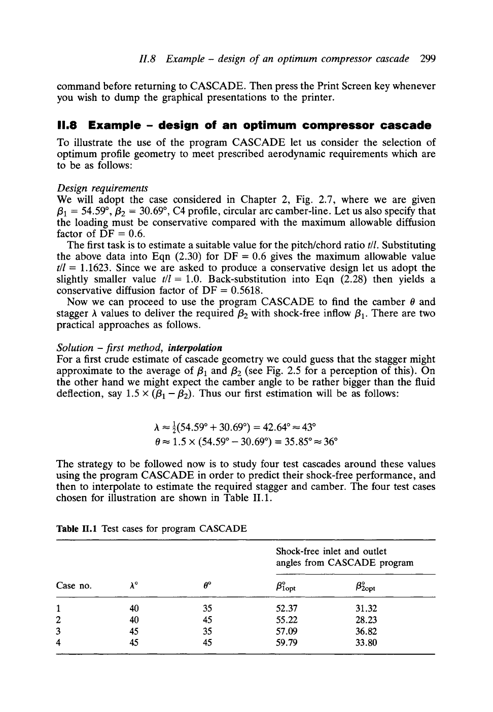
The strategy to be followed now is to study four test cascades around these values
using the program CASCADE in order to predict their shock-free performance, and
then to interpolate to estimate the required stagger and camber. The four test cases
chosen for illustration are shown in Table II.1.
Table II.1 Test cases for program CASCADE
Shock-free inlet and outlet
angles from CASCADE program
Case no. A ~ O~
~opt ~opt
1 40 35 52.37 31.32
2 40 45 55.22 28.23
3 45 35 57.09 36.82
4 45 45 59.79 33.80
300
Appendix H
I
opt
~,0-
39
58
57
36
55-
-
54-
55""'
52"
51"
30
29:
2s~
=
27~
..2
26:
25i
50
I I I
Design point
i N t
\
J
f
X
=
40 ~
0=35*
f
9
v
J2 ~
J
J
J
!
X
=45 ~
J
0=45*
J
51
52 53 54 55 56 57 58 59 60
~2 opt
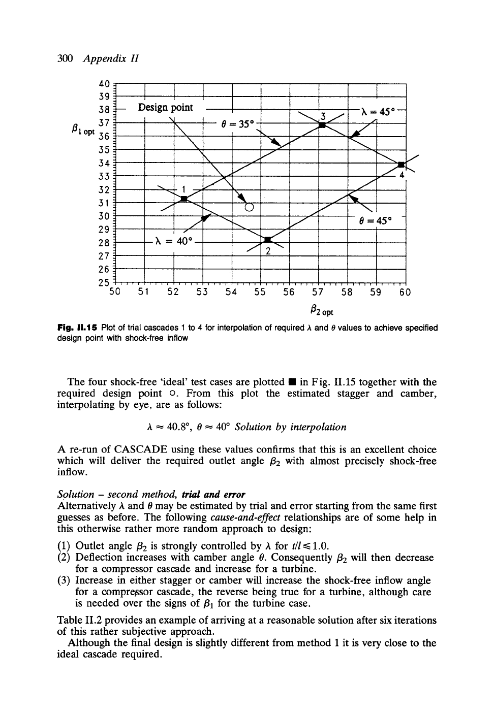
Fig, 11,15 Plot of trial cascades 1 to 4 for interpolation of required ,~ and
0
values to
achieve specified
design point with shock-free inflow
The four shock-free 'ideal' test cases are plotted II in F ig. 11.15 together with the
required design point o. From this plot the estimated stagger and camber,
interpolating by eye, are as follows:
A ~ 40.8 ~ 0 ~ 40 ~
Solution by interpolation
A re-run of CASCADE using these values confirms that this is an excellent choice
which will deliver the required outlet angle /32 with almost precisely shock-free
inflow.
Solution - second method, trial and error
Alternatively A and 0 may be estimated by trial and error starting from the same first
guesses as before. The following
cause-and-effect
relationships are of some help in
this otherwise rather more random approach to design:
(1) Outlet angle
f12
is strongly controlled by A for
t/l <<.
1.0.
(2) Deflection increases with camber angle 0. Consequently
fiE
will then decrease
for a compressor cascade and increase for a turbine.
(3) Increase in either stagger or camber will increase the shock-free inflow angle
for a compressor cascade, the reverse being true for a turbine, although care
is needed over the signs of/31 for the turbine case.
Table II.2 provides an example of arriving at a reasonable solution after six iterations
of this rather subjective approach.
Although the final design is slightly different from method 1 it is very close to the
ideal cascade required.
H.9 Contents of data file profiles
301
Table II.2 Design of a shock-free compressor cascade by trial and error selection of stagger
and camber angles
Target design values
54.59 ~ 30.69 ~
Iteration h ~ 0 ~
fll ~ f12 ~ fl]opt J~opt
1 43 36 54.59 34.26 55.49 34.31
2 40 36 54.59 31.10 52.66 31.02
3 40 38 54.59 30.46 53.23 30.40
4 40.2 38 54.59 30.67 53.42 30.62
5 40.7 39 54.59 30.88 54.18 30.86
6 40.5 39 54.59 ~ 30.67 ~ 53.99 30.64
Final design Shock-free angles
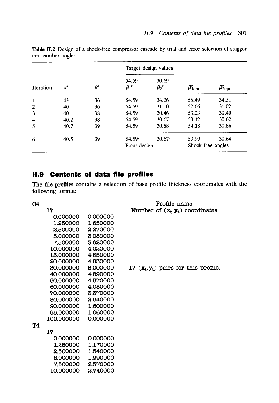
11.9 Contents of data file profiles
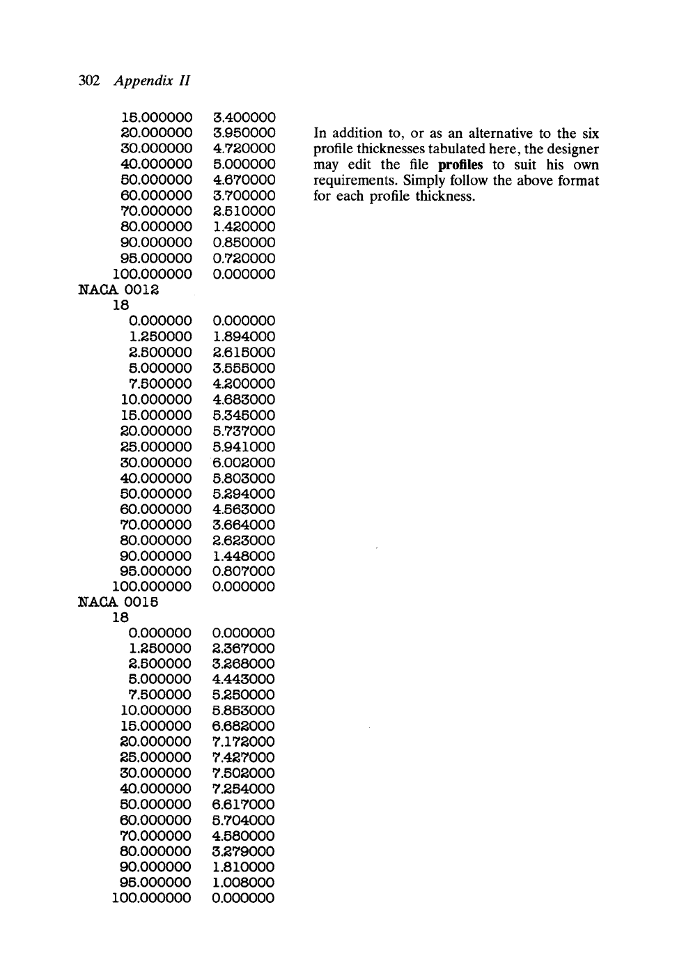
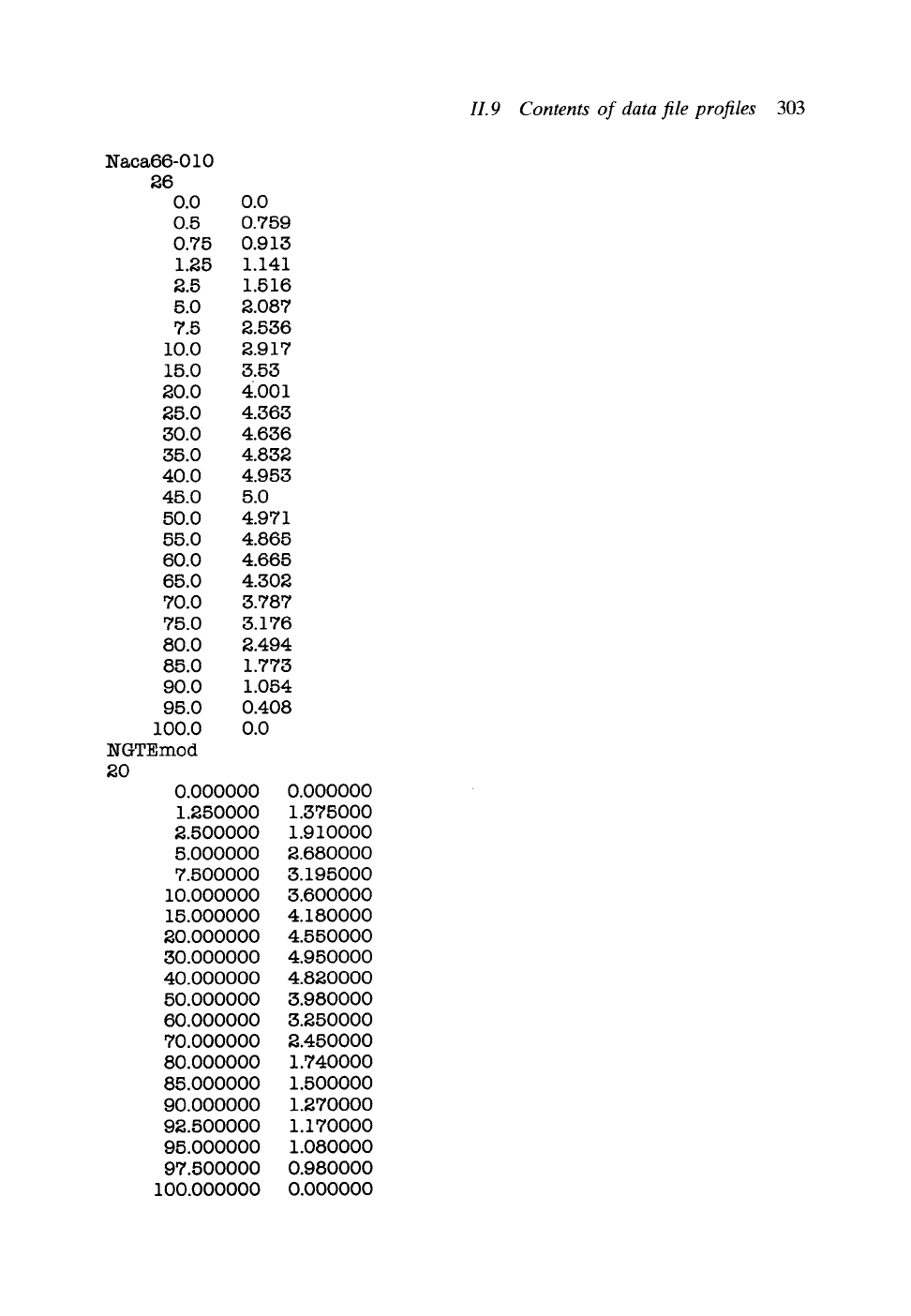
The file profiles contains a selection of base profile thickness coordinates with the
following format:
C4
T4
17
0.000000 0.000000
1.250000 1.650000
2.500000 2.270000
5.000000 3.080000
7.500000 3.620000
10.000000 4.020000
15.000000 4.550000
20.000000 4.630000
30.000000 5.000000
40.000000 4.690000
50.000000 4.570000
60.000000 4.050000
70.000000 3.370000
60.000000 2.540000
90.000000 1.600000
95.000000 1.060000
100.000000 0.000000
17
0.000000 0.000000
1.250000 1.170000
2.500000 1.540000
5.000000 1.990000
7.500000 2.370000
10.000000 2.740000
Profile name
Number of (xt, Yt) coordinates
17 (xt, Yt) pairs for this profile.
302
Appendix H
15.000000
20.000000
30.000000
40.000000
50.000000
60.000000
70.000000
80.000000
90.000000
95.000000
100.000000
NACA0012
18
0.000000
1.250000
2.500000
5.000000
7.500000
10.000000
15.000000
20.000000
25.000OOO
30.000000
4O.O0OOOO
50.000000
60.000000
70.000000
80.000000
90.000000
95.000000
100.000000
NACA0015
18
0.000000
1.250000
2.500000
5.000000
7.5OOO0O
10.000000
15.000000
20.000000
25.000000
30.000000
40.000000
50.000000
60.000000
70.000000
80.000000
90.000000
95.000000
100.000000
3.400000
3.950000
4.720000
5.OOOOOO
4.670000
3.700000
2.510000
1.420000
O.85OOO0
0.720000
0.000000
0.000000
1.894000
2.615000
3.555O00
4.200000
4.683000
5.345000
5.737000
5.941000
6.002000
5.803000
5.294000
4.563000
3.664000
2.623000
1.448000
0.807000
0.000000
0.000000
2.367000
3.268000
4.443000
5.250000
5.853000
6.682000
7.172000
7.427000
7.502000
7.254000
6.617000
5.704000
4.580000
3.279000
1.810000
1.008000
0.000000
In addition to, or as an alternative to the six
profile thicknesses tabulated here, the designer
may edit the file profiles to suit his own
requirements. Simply follow the above format
for each profile thickness.
Naca66-010
26
0.0
0.5
0.75
1.25
2.5
5.0
7.5
10.0
15.0
20.0
25.0
30.0
35.0
4O.O
45.O
50.O
55.0
60.0
65.0
70.0
75.0
80.0
85.0
90.0
95.0
100.0
NGTEmod
2O
0.0
0.759
0.913
1.141
1.516
2.087
2.536
2.917
3.53
4.oo~
4.363
4.636
4.832
4.953
5.0
4.971
4.865
4.665
4.302
3.787
3.176
2.494
1.773
1.054
O.4O8
0.0
0.000000
1.250000
2.500000
5.000000
7.500000
10.000000
15.000000
20.000000
30.000000
40.OOOOOO
50.0000O0
60.000000
70.000000
80.000000
85.O0OOOO
90.000000
92.500000
95.000000
97.500000
100.000000
0.000000
1.375000
1.910000
2.680000
3.195000
3.600000
4.180000
4.5500OO
4.950000
4.820000
3.980000
3.250000
2.450000
1.740000
1.500000
1.270000
1.170000
1.080000
0.980000
0.000000
H.9
Contents of data file profiles
303