Lewis R.I. Turbomachinery Performance Analysis
Подождите немного. Документ загружается.

284 Appendix I
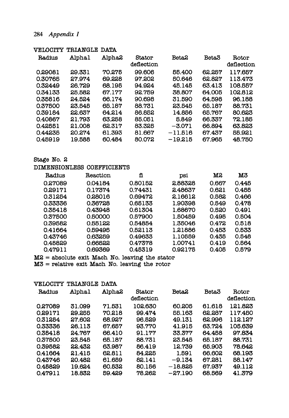
VELOCITY TRIA_I~GLE DATA
Radius Alphal Alpha2 Stator Beta2 Beta3
deflection
0.29081 29.331 70.275 99.606 55.400 62.257
0.30765 27.974 69.228 97.202 50.646 62.827
0.32449 26.729 68.195 94.924 45.145 63.413
0.34133 25.582 67.177 92.759 38.807 64.005
0.35816 24.524 66.174 90.698 31.590 64.598
0.37500 23.545 65.187 88.731 23.545 65.187
0.39184 22.637 64.214 86.852 14.856 65.767
0.40867 21.793 63.258 85.051 5.849 66.337
0.42551 21.008 62.317 83.325 -3.071 66.894
0.44235 20.274 61.393 81.667 - 11.516 67.437
0.45919 19.588 60.484 80.072 - 19.215 67.965
Rotor
deflection
117.657
113.473
108.557
102.812
96.188
88.731
80.623
72.185
63.823
55.921
48.750
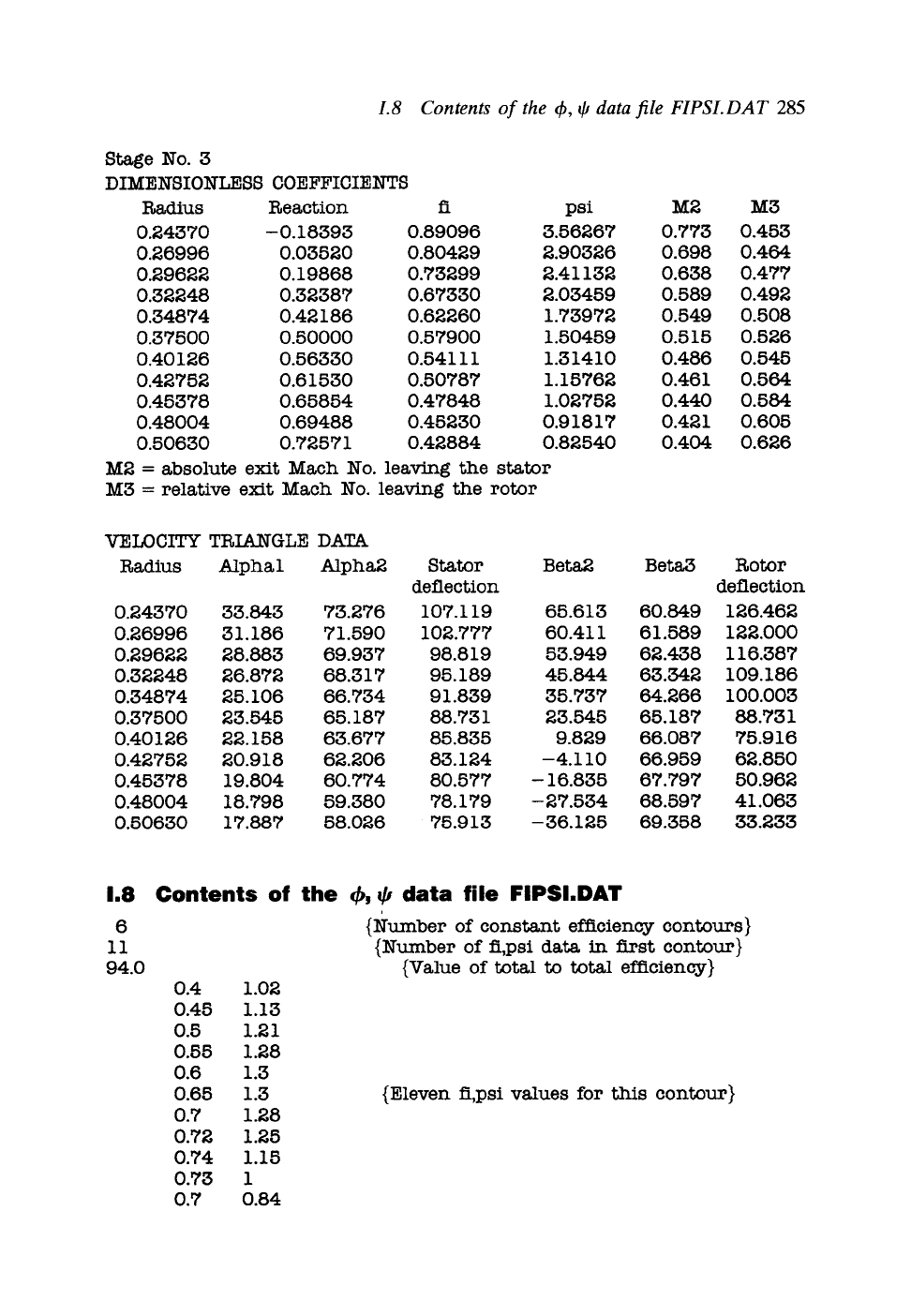
Stage No. 2
DIMENSIONLESS COEFFICIENTS
Radius Reaction fi psi
0.27089 0.04184 0.80152 2.88328
0.29171 0.17374 0.74431 2.48637
0.31254 0.28016 0.69472 2.16612
0.33336 0.36728 0.65133 1.90398
0.35418 0.43948 0.61304 1.68670
0.37500 0.50000 0.57900 1.50459
0.39582 0.55122 0.54854 1.35046
0.41664 0.59495 0.52113 1.21886
0.43746 0.63259 0.49633 1.10559
0.45829 0.66522 0.47378 1.00741
0.47911 0.69369 0.45319 0.92175
M2 = absolute exit Mach No. leaving the stator
M3 = relative exit Mach No. leaving the rotor
M2
0.667
0.621
0.582
0.549
0.520
0.495
0.472
0.453
0.435
0.419
O.405
M3
0.445
0.455
O.466
0.478
0.491
0.504
0.518
0.533
O.548
0.564
0.579
VELOCITY TRIANGLE DATA
9 Radius Alphal Alpha2 Stator Beta2 Beta3
deflection
0.27089 31.099 71.531 102.630 60.205 61.618
0.29171 29.255 70.218 99.474 55.163 62.287
0.31254 27.602 68.927 96.529 49.131 62.996
0.33336 26.113 67.657 93.770 41.915 63.724
0.35418 24.767 66.410 91.177 33.377 64.458
0.37500 23.545 65.187 88.731 23.545 65.187
0.39582 ~ 22.432 63.987 86.419 12.739 65.903
0.41664 21.415 62.811 84.225 1.591 66.602
0.43746 20.482 61.659 82.141 -9.134 67.281
0.45829 19.624 60.532 80.156 - 18.825 67.937
0.47911 18.832 59.429 78.262 -27.190 68.569
Rotor
deflection
121.823
117.450
112.127
105.639
97.834
88.731
78.642
68.193
58.147
49.112
41.379
1.8 Contents of the q~, r data file FIPSI.DAT
285
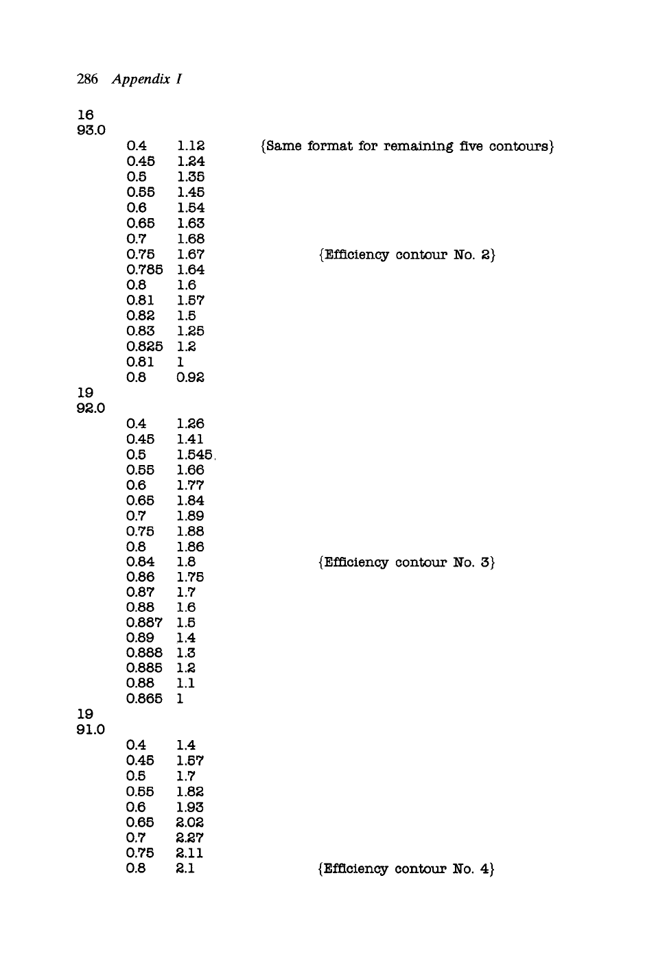
Stage No. 3
DIMENSIONLESS COEFFICIENTS
Radius Reaction fi psi M2
0.24370 -0.18393 0.89096 3.56267 0.773
0.26996 0.03520 0.80429 2.90326 0.698
0.29622 0.19868 0.73299 2.41132 0.638
0.32248 0.32387 0.67330 2.03459 0.589
0.34874 0.42186 0.62260 1.73972 0.549
0.37500 0.50000 0.57900 1.50459 0.515
0.40126 0.56330 0.54111 1.31410 0.486
0.42752 0.61530 0.50787 1.15762 0.461
0.45378 0.65854 0.47848 1.02752 0.440
0.48004 0.69488 0.45230 0.91817 0.421
0.50630 0.72571 0.42884 0.82540 0.404
M2 = absolute exit Mach No. leaving the stator
M3 = relative exit Mach No. leaving the rotor
M3
0.453
0.464
0,477
0.492
0.508
0.526
0.545
0.564
0.584
0.605
0.626
VELOCITY TRIANGLE DATA
Radius Alphal Alpha2 Stator Beta2 Beta3
deflection
0.24370 33.843 73.276 107.119 65.613 60.849
0.26996 31.186 71.590 102.777 60.411 61.589
0.29622 28.883 69.937 98.819 53.949 62.438
0.32248 26.872 68.317 95.189 45.844 63.342
0.34874 25.106 66.734 91.839 35.737 64.266
0.37500 23,545 65.187 88.731 23.545 65.187
0.40126 22.158 63.677 85.835 9.829 66,087
0.42752 20.918 62.206 83.124 -4.110 66.959
0.45378 19.804 60.774 80.577 - 16.835 67.797
0.48004 18.798 59.380 78.179 - 27.534 68.597
0.50630 17.887 58.026 75.913 -36.125 69.358
Rotor
deflection
126.462
122.000
116.387
109.186
100.003
88.731
75.916
62.850
50.962
41.063
33.233
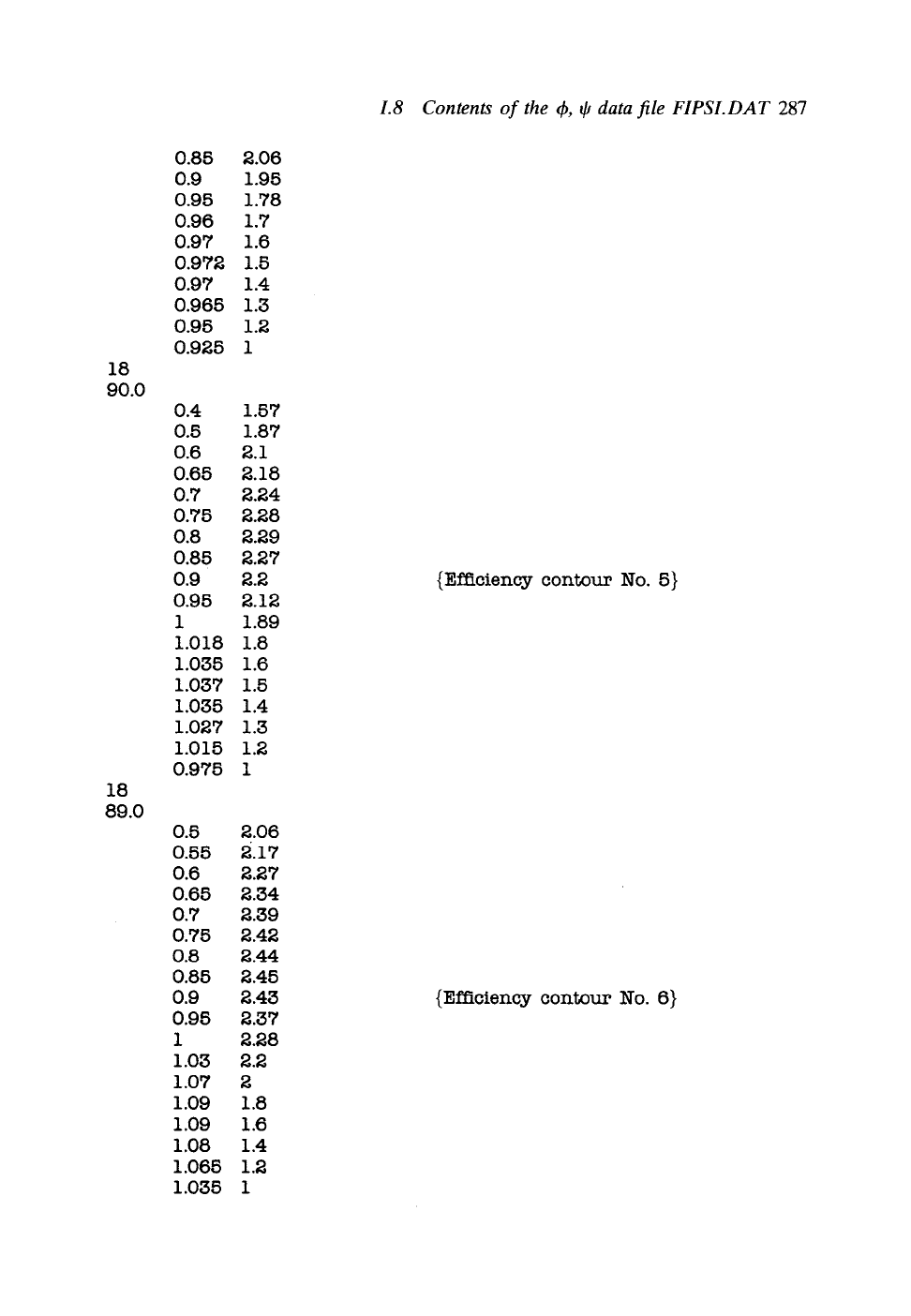
1.8
6
11
94.0
Contents of the (~, # data file FIPSI.DAT
0.4 1.02
0.45 1.13
0.5 1.21
0.55 1.28
0.6 1.3
0.65 1.3
0.7 1.28
0.72 1.25
0.74 1.15
0.73 1
0.7 0.84
{Number of constant efficiency contours}
(Number of fi,psi data in first contour)
(Value of total to total efficiency)
(Eleven fi,psi values for this contour)
286
Appendix I
16
93.0
19
92.0
lg
gl.0
0.4
0.45
0.5
0.55
0.6
0.65
0.7
0.75
0.785
0.8
0.81
0.82
0.83
0.825
0.81
0.8
0.4
0.45
0.5
0.55
0.6
0.65
0.7
0.75
0.8
0.84
0.86
0.87
0.88
0.887
0.89
0.888
0.885
0.88
0.865
0.4
0.45
0.5
0.55
0.6
0.65
0.7
0.75
0.8
1.12
1.24
1.35
1.45
1.54
1.63
1.68
1.67
1.64
1.6
1.57
1.5
1.25
1.2
1
0.92
1.26
1.41
1.545
1.66
1.77
1.84
1.89
1.88
1.86
1.8
1.75
1.7
1.6
1.5
1.4
1.3
1.2
1.1
1
1.4
1.57
1.7
1.82
1.93
2.02
2.27
2.11
2.1
{Same format for remaining five contours)
(Efficiency contour No. 2}
{Efficiency contour No. 3}
(Efficiency contour No. 4}
1.8 Contents of the d~, qJ data file FIPSI.DAT
287
18
90.0
18
89.0
0.85
0.9
0.95
0.96
0.97
0.972
0.97
0.965
0.95
0.925
0.4
0.5
0.6
0.65
0.7
0.75
0.8
0.85
0.9
0.95
1
1.018
1.035
1.037
1.035
1.027
1.015
0.975
0.5
0.55
0.6
0.65
0.7
0.75
0.8
0.85
0.9
0.95
1
1.03
1.07
1 .O9
1.09
1.08
1.065
1.035
2.06
1.95
1.78
1.7
1.6
1.5
1.4
1.3
1.2
1
1.57
1.87
2.1
2.18
2.24
2.28
2.29
2.27
2.2
2.12
1.89
1.8
1.6
1.5
1.4
1.3
1.2
1
2.06
z.17
2.27
2.34
2.39
2.42
2.44
2.45
2.43
2.37
2.28
2.2
2
1.8
1.6
1.4
1.2
1
{Efficiency contour No. 5}
{Efficiency contour No. 6}
Appendix II
'CASCADE'
A computer program for design and analysis of
turbomachine cascades
I1.1 Introduction and overview
CASCADE is a computer program for the fluid dynamic design and analysis of
turbomachine cascades. Blade profile geometry is generated by superimposing a
profile thickness distribution normal to a camber or mean line which can be either
a circular arc or a parabola, as described in Section 2.3. Alternatively the program
will accept 'raw data', namely a set of
(x,y)
profile coordinates as explained in Section
11.2.2. Once the blade row geometry has been selected the program undertakes a
fluid flow analysis based on the surface vorticity cascade method outlined in Chapter
9, Section 9.4, to predict the outlet flow angle/32 and surface pressure distribution
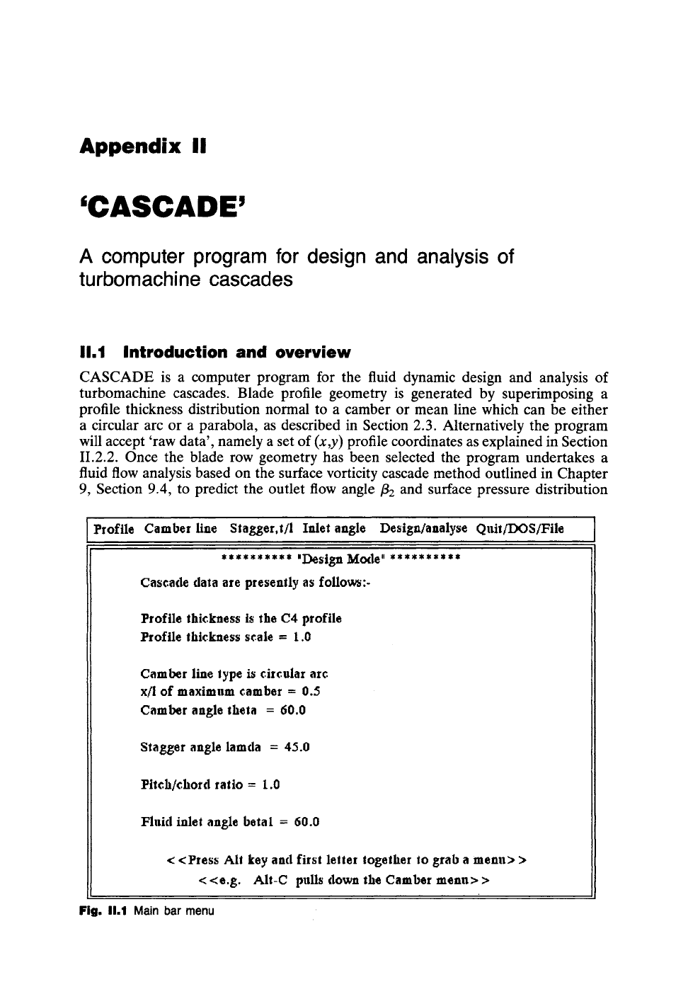
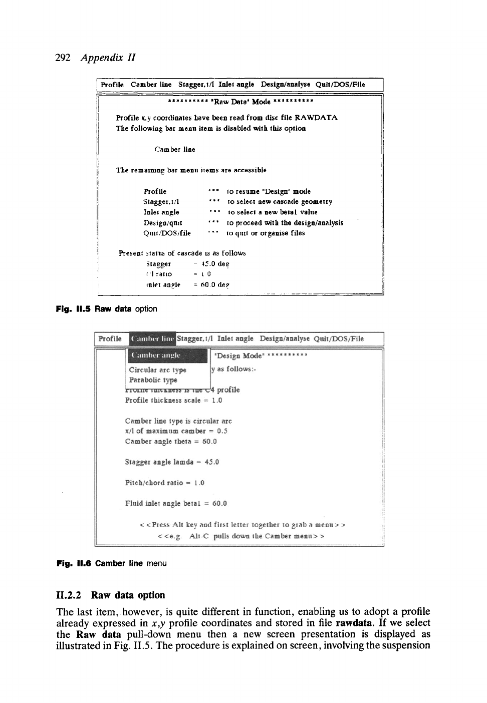
Profile Camber line Stagger, t/l Inlet angle Design/analyse Quil/DOS/File
********** 'Design Mode" **********
Cascade data are presently as follow~:-
Profile thickness is the C4 profile
Profile lhickness scale = 1.0
Camber line
lype is
circular arc
x/l of maximum camber = 0.5
Camber angle lhela = 60.0
Stagger angle lamda = 45.0
Pitch/chord ratio = t.0
Fluid inlet angle betal = 60.0
< <Pres~ All
key and first leller together lo grab a
menu>
>
< <e.g. AII-C pulls down the Camber menu> >
Fig.
I1.1 Main bar menu
H.1 Introduction and overview
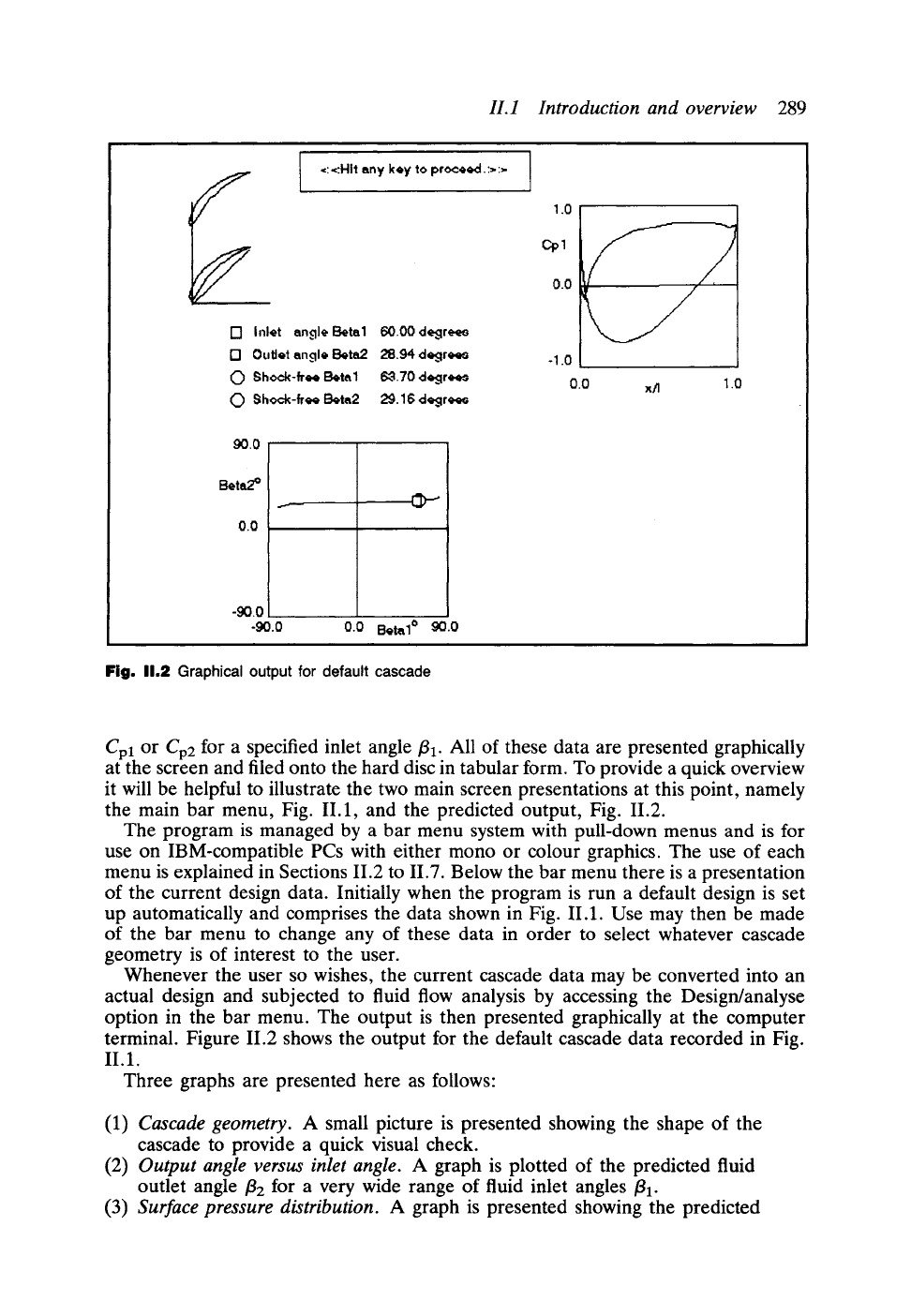
289
9 =: ,=:Hit any key to proceed. :> :=-
I"! Inlet angle Beta1 60.00 degr~
17 Outlet angle Beta2 28.94 degrees
0 Shock-free Beta1 63.70 dc~:jrc, cm
0 Shock-free Bet~2 29.16 dc~:jr~
90.0
Beta2 ~
0.0
-90.0
-90.0 0.0 Beta1 ~>" 90.0
Fig. 11.2
Graphical output for default cascade
1.0
cpl
0.0
-1.0
0.0 x/I 1.0
Cpl
or Cp2
for a specified inlet angle
ill"
All of these data are presented graphically
at the screen and filed onto the hard disc in tabular form. To provide a quick overview
it will be helpful to illustrate the two main screen presentations at this point, namely
the main bar menu, Fig. II.1, and the predicted output, Fig. II.2.
The program is managed by a bar menu system with pull-down menus and is for
use on IBM-compatible PCs with either mono or colour graphics. The use of each
menu is explained in Sections II.2 to II.7. Below the bar menu there is a presentation
of the current design data. Initially when the program is run a default design is set
up automatically and comprises the data shown in Fig. II.1. Use may then be made
of the bar menu to change any of these data in order to select whatever cascade
geometry is of interest to the user.
Whenever the user so wishes, the current cascade data may be converted into an
actual design and subjected to fluid flow analysis by accessing the Design/analyse
option in the bar menu. The output is then presented graphically at the computer
terminal. Figure II.2 shows the output for the default cascade data recorded in Fig.
II.1.
Three graphs are presented here as follows:
(1)
Cascade geometry.
A small picture is presented showing the shape of the
cascade to provide a quick visual check.
(2)
Output angle versus inlet angle.
A graph is plotted of the predicted fluid
outlet angle
f12
for a very wide range of fluid inlet angles
ill-
(3)
Surface pressure distribution.
A graph is presented showing the predicted
290
Appendix H
surface pressure coefficient
Cpl or
Cp2 versus fractional distance along the
chord line
x/l.
The surface pressure coefficients are defined as follows:
' P
-Pl
Up1 --
1 2 for a compressor (II. 1)
~pW1
Cp2 = Pl - P22 for a turbine (11.2)
~pW~
The default design illustrated in Fig. 11.2 is a compressor cascade for which the stagger
is positive, +45 ~ A turbine cascade is selected by simply specifying a negative stagger
value, e.g. -60 ~ The program then automatically selects either Cpl or Cp2 as defined
above.
II.1.1 How to run the program
Before running the program CASCADE it is essential to have the file
profiles
available in the current directory. The contents of this are given in Section 11.9 and
may be extended to include other profile thicknesses by following the given format.
To run the program simply enter its name cascade at the keyboard. The title page
which is then presented at the screen can be removed by hitting any key, whereupon
the main bar menu and default design data, Fig. II.1, will then appear at the screen.
To access any item in the bar menu simply press down the Alt key while hitting the
first character of the keyword as explained at the bottom of the screen.
11.1.2 Main bar menu
Referring back to Fig. II.1, there are six keywords in the main bar menu which
perform the following functions:
Profile To select the profile base thickness distribution.
Camber line
To select the camber angle and type of curvature.
Stagger, t/l To select the cascade geometrical parameter stagger and
pitch/chord ratio.
Inlet
angle To select the inflow angle/31.
Design/analyse To convert the above design data into a cascade and calculate its
fluid-dynamic performance.
Quit/DOS/File To enable you to quit, to go temporarily into DOS, to file your
current work or to read the previous work from file, or to
reverse the video presentation.
We will now deal with these in more detail in the following six sections.
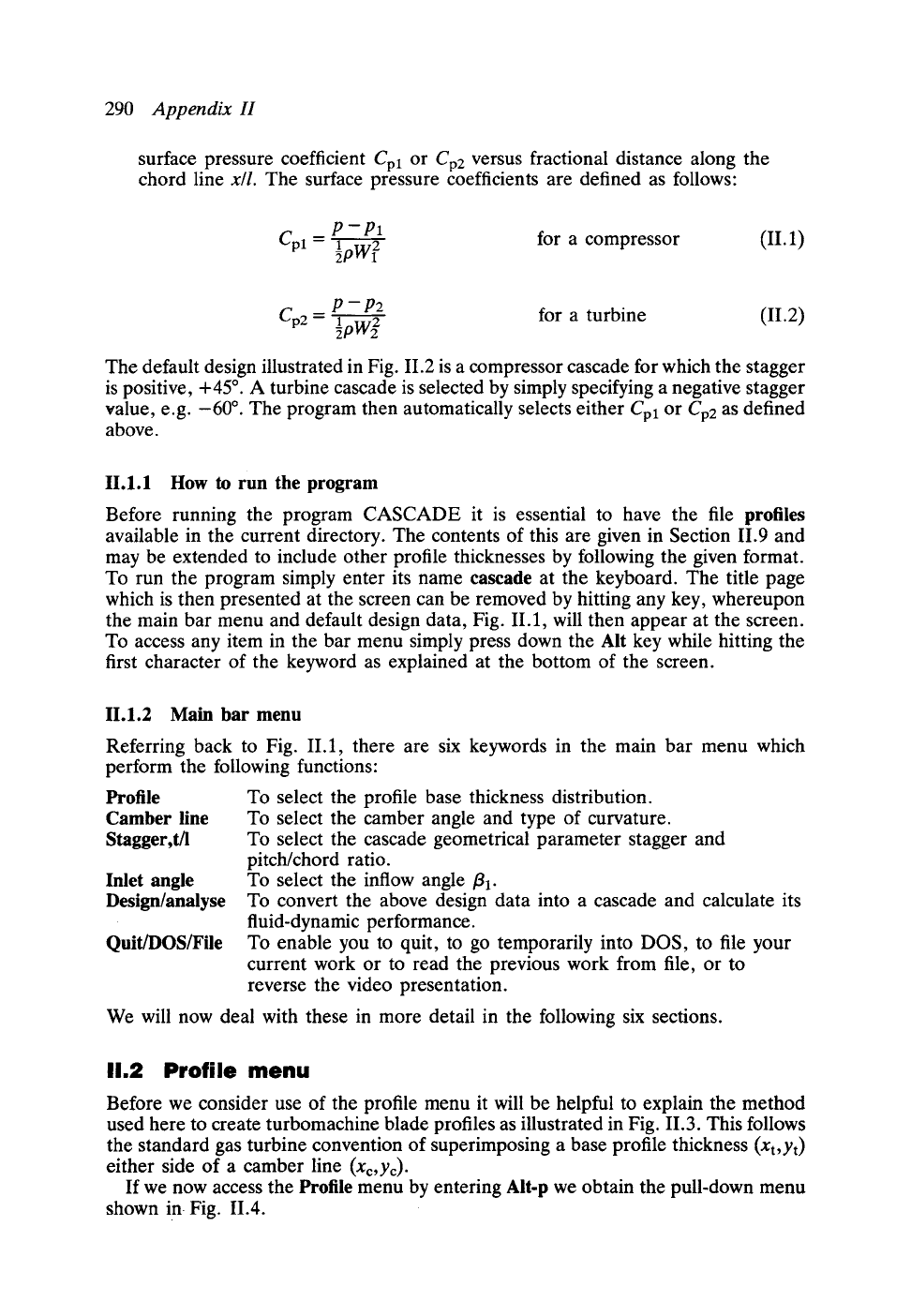
11.2 Profile menu
Before we consider use of the profile menu it will be helpful to explain the method
used here to create turbomachine blade profiles as illustrated in Fig. 11.3. This follows
the standard gas turbine convention of superimposing a base profile thickness
(xt,Yt)
either side of a camber line (xe,yc).
If we now access the Profile menu by entering Alt-p we obtain the pull-down menu
shown in Fig. 11.4.
H.2 Profile menu
291
Fig. 11.3 Method of construction of a turbomachine blade profile
Fig. 11.4 The Profile pull-down menu
11.2.1 Selection of a base profile thickness
The 1' $ arrow keys enable us to highlight the profile of our choice, which may
then be accepted by pressing <Enter>. Thus in Fig. 11.4 the axial compressor
Profile
- C4 had been selected. Following this the user is invited to specify the profile
thickness scale. If the value 1.0 is entered then the standard profile thickness shape
will be used to generate the Yt values, Fig. 11.3, otherwise some other value may be
used to thicken or thin the profile. The first six items on this pull-down menu provide
a range of typical profile thicknesses to suit many turbomachine applications.
292
Appendix H
Profile Camber line Stagger, t/l Inlet angle Design/analyse Quit/DOS/File
****'***** "Raw Data' Mode ****'*****
Profile x,y coordinates have been read from disc file RAWDATA
The following bag menu item is disabled with this option
Camber line
The remaining bar menu items are accessible
Profile
S tagge t, t/1
Inlet angle
Design/quit
Q nit/DOS/file
*** to resume "Design" mode
"** to select new cascade geometry
' *" to select a new betaI value
""* to proceed with the design/analysis
"*" to quit or organise files
Present status of cascade ts as follows
, ~tagger - ~.0
(lee
r'! ratio = ~ 0
i ~niet an.~ie = a0.0 (le~,
i ...................................
Fig. 11.5 Raw data option
Fig.
11.6 Camber line menu
11.2.2 Raw data option
The last item, however, is quite different in function, enabling us to adopt a profile
already expressed in
x,y
profile coordinates and stored in file rawdata. If we select
the Raw data pull-down menu then a new screen presentation is displayed as
illustrated in Fig. 11.5. The procedure is explained on screen, involving the suspension

H.2
293
0.80
Profile
menu
Position of
maximum
camber.
0.40
0 O0
"0.0 L Oa.x2O 0.40 0.60 0.80 1.()0
x I
"--=
chord
_...,
Fig. 11,7 Parabolic camber line
Fig. 11.8 Menu for selecting cascade geometry
of the Camber line pull-down menu. With this option the given profile shape read
from rawdata can be set at your own choice of stagger and camber and a flow analysis
undertaken at any chosen flow inlet angle/31. The format for data in file rawdata
is as illustrated in Section II.10, and the author's other program STACK, for
geometrical design and stacking of turbomachine blade profiles, saves its output into
a file of the same name, rawdata, which can contain up to eleven different
profiles.