Lewis R.I. Turbomachinery Performance Analysis
Подождите немного. Документ загружается.

234
Ducted propellers and fans
10.0
8.0
fa
6.0
4.0
2.0-
0.0
0 i ~ ~ i 5 6 ) 8 9 ~0
CT
~-----r = 0.5
-.~1~ 0.6
-gE------- 0.7
0.8
1.0
1.2
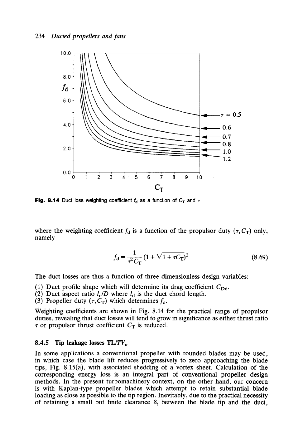
Fig. 8.14 Duct loss weighting coefficient fd as a function
of
C T
and
r
where the weighting coefficient fd is a function of the propulsor duty (z, CT) only,
namely
1 (1 + V1 + ~CT) 2 (8.69)
/a= ~2CT
The duct losses are thus a function of three dimensionless design variables:
(1) Duct profile shape which will determine its drag coefficient CDd-
(2) Duct aspect ratio
ld/D
where ld is the duct chord length.
(3) Propeller duty (r, CT) which determines fd.
Weighting coefficients are shown in Fig. 8.14 for the practical range of propulsor
duties, revealing that duct losses will tend to grow in significance as either thrust ratio
r or propulsor thrust coefficient CT is reduced.
8.4.5 Tip leakage losses TL/TVa
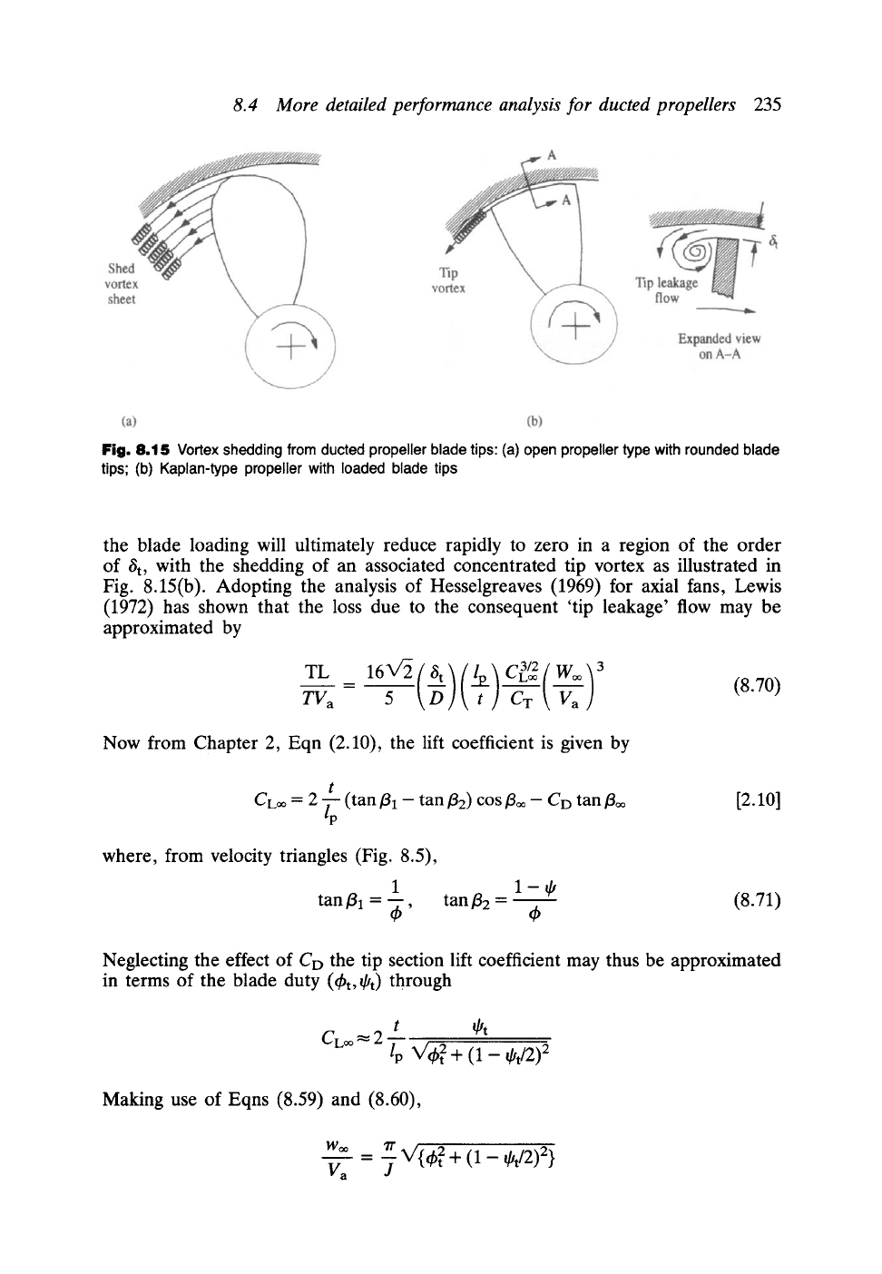
In some applications a conventional propeller with rounded blades may be used,
in which case the blade lift reduces progressively to zero approaching the blade
tips, Fig. 8.15(a), with associated shedding of a vortex sheet. Calculation of the
corresponding energy loss is an integral part of conventional propeller design
methods. In the present turbomachinery context, on the other hand, our concern
is with Kaplan-type propeller blades which attempt to retain substantial blade
loading as close as possible to the tip region. Inevitably, due to the practical necessity
of retaining a small but finite clearance
8 t
between the blade tip and the duct,
8.4 More detailed performance analysis for ducted propellers
235
Fig. 8.15 Vortex shedding from ducted propeller blade tips: (a) open propeller type with rounded blade
tips; (b) Kaplan-type propeller with loaded blade tips
the blade loading will ultimately reduce rapidly to zero in a region of the order
of St, with the shedding of an associated concentrated tip vortex as illustrated in
Fig. 8.15(b). Adopting the analysis of Hesselgreaves (1969) for axial fans, Lewis
(1972) has shown that the loss due to the consequent 'tip leakage' flow may be
approximated by
= ,-.Loo W~ (8.70)
TV a 5 C T
Now from Chapter 2, Eqn (2.10), the lift coefficient is given by
t
CLoo -- 2 -7-
(tan
J~l --
tan f12)
COS floo -- CD
tan/3oo
~p
[2.10]
where, from velocity triangles (Fig. 8.5),
1
tan/31 = ~b'
tanfl2 = ~ (8.71)
Neglecting the effect of Co the tip section lift coefficient may thus be approximated
in terms of the blade duty (~bt, St) through
t ~t
CLoo
2
~p X/4h 2 + (1 - @t/2) 2
Making use of Eqns (8.59) and (8.60),
woo = rr V'{ ~b 2 + (1 - Ot/2) 2}
Va J
236
Ducted propellers and fans
so that finally the tip leakage loss, Eqn (8.70), becomes
TV a - 5 O CT J'''--'~ -'-2"-
8 t t
1/2
21
3/4
(8.72)
The tip leakage losses are thus a function of the dimensionless tip clearance
~t/D,
the tip section pitch/chord ratio
t/lp
and a loss weighting coefficient
ftl
dependent upon
the propulsor duty
(z, CT,J)
and the propeller tip section duty (~bt, @t), namely
ft1=645
CTJ 3 ~r3
~t/2{th2+ (
_~) 2 } 3/4
1 - (8.73)
Example 8.3
A breakdown of the predicted losses based on the above formulations is shown here
in Table 8.2 including the consequent predicted propulsive efficiency r/p for a typical
Kort Nozzle ducted propeller for a wide range of duties. The performance
characteristic (CT, r,J) data have been derived by Lewis (1972) from the published
experimental results of Van Manen and Oosterveld (1966), and values of other design
data have been assumed as follows:
Tip section
t/lp
= 1.82
Duct aspect ratio
ld/D
= 0.5
Propeller drag coefficient CDp = 0.006 (based on NACA 64-008)
Duct drag coefficient CDd = 0.02 (pessimistic value to include hub)
The following points are worthy of note"
(1) To obtain the above characteristic data a suitable approach would be to keep
the propulsor forward velocity Va constant and to vary the propeller speed of
rotation n in order to change the advance coefficient J =
Va/nD
over the
given range 0.372 <J<0.610.
(2) Over this range of J the thrust coefficient CT varies enormously from 2.7 to
7.57.
(3) Curiously, however, the propeller duty at the tip radius varies very little from
the central design duty ~bt = 0.316 87, @t = 0.041 01. Furthermore the vector
mean flow angle relative to the blade tips/3~ also varies by only 2 ~ over the
operating range, demonstrating a remarkable advantageous feature of ducted
propellers. The effect of the duct in augmenting the velocity Vp in the
propeller plane is such that, if the propeller rotational speed is increased, Vp
also increases, the outcome being that the angle of attack/31 and the vector
mean angle/3~ remain almost unchanged over 2.7 < CT< 7.57. Thus the duct
provides the optimum hydrodynamic environment for the propeller blades,
enabling typical Kort Nozzle propulsors to operate over a very wide range of
thrust coefficients Ca,.
(4) The predominant loss is that contributed by the jet axial kinetic energy
Ew/TVa.
Next in line is the propeller profile loss
Fp/TVa.
Together these
provide about 78% of the total losses at the lowest Ca- rising to 86.3% at the
8.5 Prediction of Kort Nozzle ducted propeller characteristic curves 237
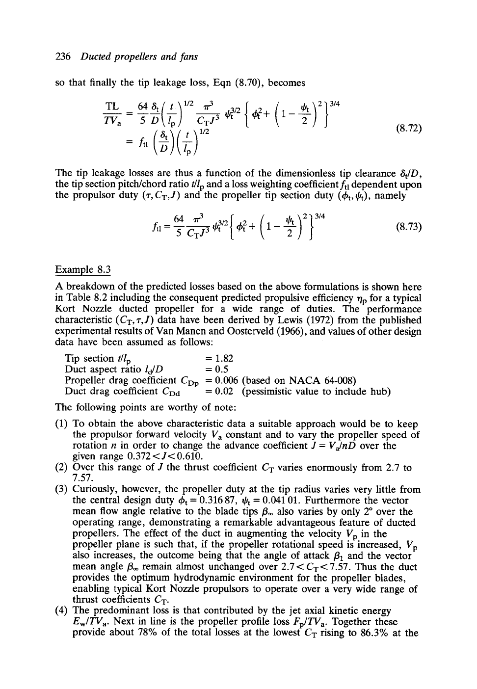
Table
8.2 Predicted loss coefficients for Van Manen Screw Series B4-55 with Nozzle
No. 19A
CT | 2.7 3.5 4.5 6.0 7.57
z I Van Manen and 0.785 0.751 0.725 0.7 0.675
J Oosterveld (1966) 0.610 0.525 0.471 0.410 0.372
~b t ]
Propeller duty 0.342 11 0.323 20 0.316 87 0.305 79 0.304 52
qh ~ at tip radius 0.045 02 0.041 06 0.041 01 0.039 93 0.040 00
/3~ 70.71 ~ 71.74 ~ 72.07 ~ 72.67 ~ 72.74 ~
Ew/TVa 0.383 11 0.452 43 0.532 29 0.640 18 0.735 90
Sw/TV a
0.112 90 0.107 37 0.113 14 0.117 68 0.124 77
Fp/TV a 0.177 85 0.212 60 0.227 70 0.256 77 0.272 15
Fd/TV a 0.045 99 0.042 75 0.039 71 0.036 60 0.034 95
Total loss 0.719 85 0.815 14 0.912 84 1.051 22 1.167 75
Predicted propulsive efficiency 58.14
np
(%)
55.09 52.28 48.75 46.13
highest CT, both varying considerably over the operating range. Swirl losses
Sw/TVa are small by comparison but by no means insignificant. On the other
hand, the thrust losses due to duct drag are trivial by comparison.
8.5
Prediction of Kort Nozzle ducted propeller
characteristic curves
Each set of (CT, r,J) data given at the top of Table 8.2 were derived from
experimental tests. Thus for a given forward speed Va in open water J = Va/nD can
be varied simply by changing the propeller rotational speed n. The above measured
data are then usually expressed by two characteristic curves of the form ~" versus CT
and J versus CT. In the following sections simple theoretical analyses will be presented
which produce remarkably good predictions of off-design characteristics r(CT)
and J(CT) for Kort Nozzle propulsors given a prescribed central design duty
(CTo, ~o,Jo).
8.5.1 The "r(CT) characteristic
Lewis (1973) developed the following method for predicting the z(CT) characteristic
beginning with the hypothesis that the duct forward thrust Td is proportional to the
square of the radially inward downwash velocity induced by the jet wake, Fig.
8.16.
To establish the relationship between To and the wake shed vorticity Fw let us
consider first the analogy with the fiat plate aerofoil shown in Fig. 8.17. The lift
generated as a result of its total bound vorticity F is given by the Magnus law,
L = pWF. But from the theory for the flat plate aerofoil (Batchelor, 1970), the
magnitude of F is given by
F = ~'lW sin a
where l is the chord length, W the mainstream velocity and a its angle of attack
238
Ducted propellers and fans
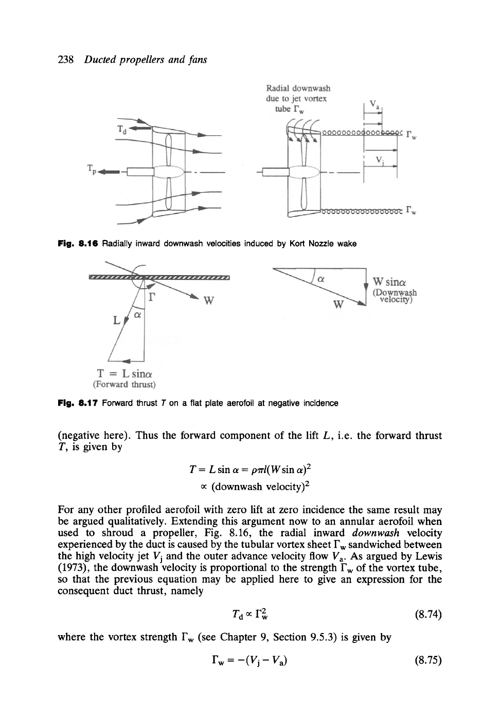
Fig. 8.16 Radially inward downwash velocities induced by Kort Nozzle wake
Fig. 8.17 Forward thrust T on a flat plate aerofoil at negative incidence
(negative here). Thus the forward component of the lift L, i.e. the forward thrust
T, is given by
T = L sin a =
pzrl(W
sin a) 2
oc (downwash velocity) 2
For any other profiled aerofoil with zero lift at zero incidence the same result may
be argued qualitatively. Extending this argument now to an annular aerofoil when
used to shroud a propeller, Fig. 8.16, the radial inward
downwash
velocity
experienced by the duct is caused by the tubular vortex sheet Fw sandwiched between
the high velocity jet Vj and the outer advance velocity flow Va. As argued by Lewis
(1973), the downwash velocity is proportional to the strength Fw of the vortex tube,
so that the previous equation may be applied here to give an expression for the
consequent duct thrust, namely
Td ~ F 2 (8.74)
where the vortex strength Fw (see Chapter 9, Section 9.5.3) is given by
rw = -(vj- Va) (8.75)

8.5 Prediction of Kort Nozzle ducted propeller characteristic curves
239
Improving slightly upon Eqn (8.20) by subtracting the hub area from the propeller
swept area, the propeller thrust becomes
vj 2
Tp - (102 -Pl) --~ (1 - h 2) -
pV 2 Va
1
"n'D 2
= rT
= 'tOT- ~
pV2a 4
-1} ~~3----~2 (1-h 2)
(8.76)
which reduces to the following, slightly more accurate, development of Eqn (8.24):
~/ rCT
Vj = 1 + (8.76a)
Va 1 --~2
Finally the jet bounding vorticity is related to (r, CT) through
Fw = 1 + 1
Va 1 -~2
(8.77)
Now the duct forward thrust To may also be expressed as
1
7rD 2
T0=(1-z)T=(1-z)CT~
V 2 4
(8.78)
Introducing the last two results into the
downwash
equation (8.74) we have the
proportionality
(1
- '/')CT0r
1 + 1
- h 2
1
Recalling our hypothesis that this condition is true for all thrust coefficients, it may
be applied also to the central design duty (CTo, Zo), resulting in the following
identity:
(1 --r)CT
(1 - to)
CTo
~/ ,/.CT 11 2
1
+ 1_-~2
7.o CTo
or, rearranging to isolate
r,
~/1+
r-l-(1-zo) ~/1+
,/.CT 2
1 -h 2 11
'to CTo
1
-
h 2
CTo
CT
(8.79)
240
Ducted propellers and fans
which has the general form of the required performance characteristic r =f(CT).
However, r cannot be completely isolated but does also appear on the right-hand
side of Eqn (8.79). Its solution must therefore be obtained by successive approxima-
tion, with each improved estimate of r being reintroduced into the right-hand side.
Convergence is found to be rapid.
8.5.2 The
J(CT,'r)
characteristic
The J(Cr, r)
characteristic represents the relationship between speed of rotation and
thrust. Since thrust is dependent upon blade loading and velocity triangles, which
differ for each radius, we shall assume that conditions at the r.m.s, radius rms are
representative of the integrated effect of the whole propeller, defining
rms = V'l(r2h + ~) (8.80)
At this radius the cascade static pressure rise coefficient
Cpm
follows directly from
velocity triangles, Fig. 8.5:
P2 -- Pl =
tan 2
film --
tan2 fl2m (8.81)
Cpm = 1 2
pVp
It can be shown that for cascades with pitch/chord ratio greater than 1.0, the fluid
deflection e =/31 -/32 remains almost constant for small variations of/31 such as were
shown to occur in Kort Nozzle propulsors in the previous section. Thus we may assert
the following assumption for the off-design duty:
8 = film-- fl2m = eo = fllmo-- ~2mo
(8.82)
Now from Eqn (8.76)
Cpm
may be derived from another direction:
Cpm - 1 - h 2
Introducing Eqn (8.76a) into (8.28a),
Va 2z
Vp (1 + V'I +
rCT/(1 -- h2))
2,1 h2,( 1+
CT 1
-h 2
1)
(8.83)
so that
Cpm
becomes
Cpm 4(1 _ h2)r( ~1 + ,rC T
)2
= CT 1
--
h 2
1 (8.84)
Finally we may eliminate
film
from Eqn (8.82) to produce a system of equations
involving J, CT, r and/32m. Thus
film
may be expressed as
Um 2"n'n rms Va
tan ~lm = -- =
Vp V a Vp
(J 1+
q-C T
1 - h 2
1)
(8.85)
8.5 Prediction of Kort Nozzle ducted propeller characteristic curves 241
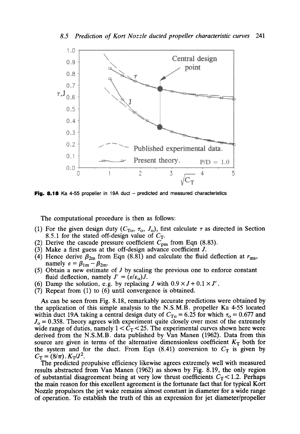
Fig. 8,18
Ka 4-55 propeller in 19A duct - predicted and measured characteristics
The computational procedure is then as follows:
(1)
(2)
(3)
(4)
(5)
(6)
(7)
For the given design duty (CTo, Zo, Jo), first calculate z as directed in Section
8.5.1 for the stated off-design value of CT.
Derive the cascade pressure coefficient
Cpm
from Eqn (8.83).
Make a first guess at the off-design advance coefficient J.
Hence derive
fl2m
from Eqn (8.81) and calculate the fluid deflection at
rms,
namely e
= film- fl2m-
Obtain a new estimate of J by scaling the previous one to enforce constant
fluid deflection, namely J' =
(e/eo)J.
Damp the solution, e.g. by replacing J with 0.9 x J + 0.1 x J'.
Repeat from (1) to (6) until convergence is obtained.
As can be seen from Fig. 8.18, remarkably accurate predictions were obtained by
the application of this simple analysis to the N.S.M.B. propeller Ka 4-55 located
within duct 19A taking a central design duty of CTo = 6.25 for which ~'o = 0.677 and
Jo = 0.358. Theory agrees with experiment quite closely over most of the extremely
wide range of duties, namely 1 < CT < 25. The experimental curves shown here were
derived from the N.S.M.B. data published by Van Manen (1962). Data from this
source are given in terms of the alternative dimensionless coefficient KT both for
the system and for the duct. From Eqn (8.41) conversion to CT is given by
C T = (8]Tr).KT/J 2.
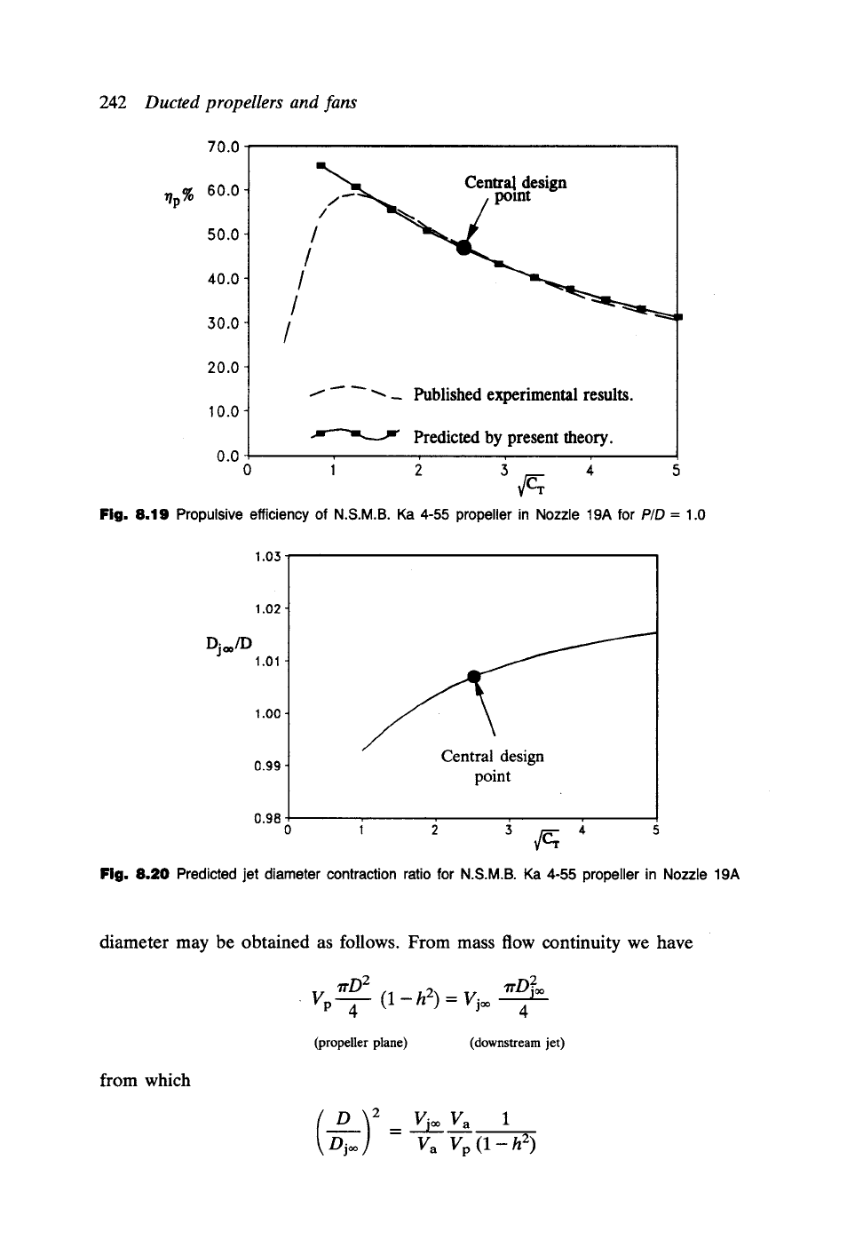
The predicted propulsive efficiency likewise agrees extremely well with measured
results abstracted from Van Manen (1962) as shown by Fig. 8.19, the only region
of substantial disagreement being at very low thrust coefficients CT < 1.2. Perhaps
the main reason for this excellent agreement is the fortunate fact that for typical Kort
Nozzle propulsors the jet wake remains almost constant in diameter for a wide range
of operation. To establish the truth of this an expression for jet diameter/propeller
70.0
~p%
60.0
50.0
40.0
30.0
20.0
10.0
1.03
Central design
//~--~~~. /pomt
//
i-" "~_ Published experimental results.
Predicted by present theory.
0.0
Fig. 8.19 Propulsive efficiency of N.S.M.B. Ka 4-55 propeller in Nozzle 19A for
P/D
= 1.0
Dj|
1.01
1.02
1.00
0.99
Central design
point
0.98
242
Ducted propellers and fans
Fig. 8.20 Predicted jet diameter contraction ratio for N.S.M.B. Ka 4-55 propeller in Nozzle 19A
diameter may be obtained as follows. From mass flow continuity we have
7rD 2
VP 4
(l-h2) = Vj= 1rO~=
4
(propeller plane) (downstream jet)
from which
D ) Vj=Va 1
Djoo = Va Vp(1-h 2)
8.5 Prediction of Kort Nozzle ducted propeller characteristic curves
243
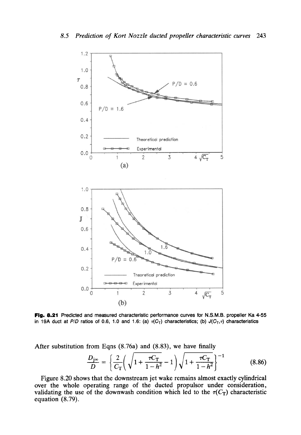
Fig. 8.21 Predicted and
measured characteristic performance
curves for N.S.M.B. propeller Ka 4-55
in 19A duct at
P/D
ratios of 0.6, 1.0 and 1.6: (a) 'r(CT) characteristics; (b) J(CT,~') characteristics
After substitution from Eqns (8.76a) and (8.83), we have finally
D ~ 1+ l_h2 1 1+ l_h2
(8.86)
Figure 8.20 shows that the downstream jet wake remains almost exactly cylindrical
over the whole operating range of the ducted propulsor under consideration,
validating the use of the downwash condition which led to the r(Cx) characteristic
equation (8.79).