Lewis R.I. Turbomachinery Performance Analysis
Подождите немного. Документ загружается.

214
Ducted propellers and fans
Various dimensionless parameters have been defined for handling propeller
performance analysis but of particular importance are the
thrust coefficient
CTo and
the
propulsive efficiency
7/p. CTo is defined as
CTo =
rp
1 2 7rD2
~pVa 4
(8.8)
which, through Eqn (8.6), is given in terms of the dimensionless jet velocity
Vjo/Va
by
CTo = \ Va - 1
= a 2-
1 (8.9)
where
Vjo = a (8.10)
Va
A suitable definition of propulsive efficiency may be expressed as
~'/p =
Propulsive power delivered to vehicle, P
P
P+ Ew
Shaft input power, Ps
(8.11)
Thus the shaft input P~ has to provide both the useful propulsive power P and the
kinetic energy losses Ew dissipated ultimately by the jet wake, which may be
expressed as follows. Firstly the propulsive power P delivered to the vehicle may be
expressed through
P = Tp Va = Thrust • speed of vehicle
= pTrD.___~ 2 (V2o - V 2)
V a .
8
= pTrD2V3a
(a 2- 1) (8 12)
8
Secondly the wake kinetic energy loss due to mixing of the jet finally at x = o0 is
ew = 89 Va) 2
and making use of Eqns (8.2) and (8.7)
EW "~
p,rrD 2
16 (Vjo- Va)2(Va
+ Vjo)
p,n.D2 V 3
(a- 1)2(a + 1)
16
(8.13)
8.1 One-dimensional actuator disc performance analysis for open propellers
215
100
80
r/p %
60
40
20
100
r/p %
60
40
20
0
0 1
0
1.0 1.5 2.0 2.5 3.0 2 3 4 5
Vjo]W a - a CTo
(a)
(b)
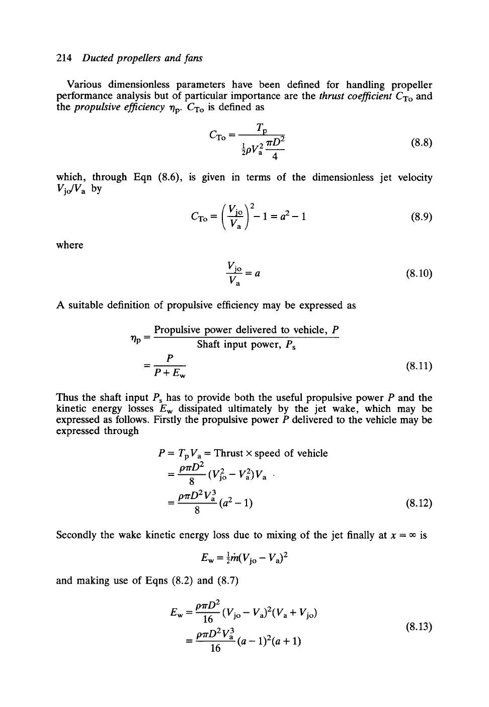
Fig. 8.4 Open propeller propulsive efficiency versus
Vjo/V a
and GTo: (a) effect of jet velocity upon rip;
(b) effect of thrust coefficient upon T/p
Introducing these results into Eqns (8.11), the propulsive efficiency may be expressed
directly in terms of
Vjo/Va
through
2 2
= = (8.14)
"rip
1
+ Vjo]V a
1 + a
Alternatively, eliminating
Vjo/Va
from Eqn (8.9), r/p may be expressed as a unique
function of the thrust coefficient only, namely
2
'0p
~-
1 + V'I
+ CTo
(8.15)
Graphs portraying these important and very interesting functional relationships are
shown in Fig. 8.4. As the jet velocity ratio
Vjo/Va
is increased to raise the design
choice of thrust coefficient CTo, SO the kinetic energy dissipated in the propeller wake
will also increase, resulting in a progressive reduction of propulsive efficiency, Fig.
8.4(a).
This is also borne out by Fig. 8.4(b) which reveals a very rapid reduction of r/p
as the selected design value of CTo is increased for lightly loaded propellers in the
range 0 < CTo < 1.0 and a progressive reduction of r/p for higher values of CTo. To
obtain a feel for likely practical levels of CTo it is necessary to consider the propeller
blade hydrodynamic or aerodynamic loading and this we will undertake in the next
section in relation to the earlier consideration of axial fans in Chapter 4.
8.1.1 Velocity triangles and duty coefficients for open propellers
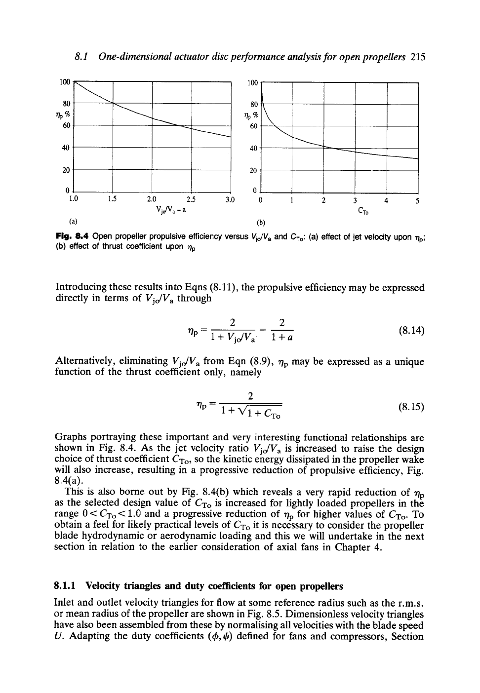
Inlet and outlet velocity triangles for flow at some reference radius such as the r.m.s.
or mean radius of the propeller are shown in Fig. 8.5. Dimensionless velocity triangles
have also been assembled from these by normalising all velocities with the blade speed
U. Adapting the duty coefficients (~b, ~,) defined for fans and compressors, Section
216 Ducted propellers and fans
~
C x =
Vpo
"0 = tO
"-- U
W /32~ ~~
~~ ~ 2
u
w2 ~ ~
1.0
Nom~lised velocity triangles
Fig. 8.5 Velocity triangles for a propeller..
4.1, for the propeller in incompressible flow, we then have
r
U
= pU 2
(8.16)
where flow coefficient ~b relates to the axial velocity Vpo in the plane of the propeller.
Combining Eqns (8.4), (8.8) and (8.7) the thrust coefficient may be developed as
follows:
_ P2- P l _ 89 w~)( Vpo~
CTo
-- 1 2 -- 1 2
~pVa ~pVpo Va ]
w 2 - w 2 (1 +
a) 2
= U2~2 •
But from the dimensionless velocity triangles
- -ff = [1
+ t~ 2] -[(1 -
0) 2
+ t~ 2]
= 0(2 - O)
so that Cxo is related to the duty coefficients ~k and ~, and the jet velocity ratio a
through
CT o --
~(2- ~)(1 + a) 2
4q~ 2
8.1 One-dimensional actuator disc performance analysis for open propellers 217
4.0
CTo/
3.0
2.0
1.0
--- o
0.0
0.5 017 0.'9 1:1 1:,3 1.5
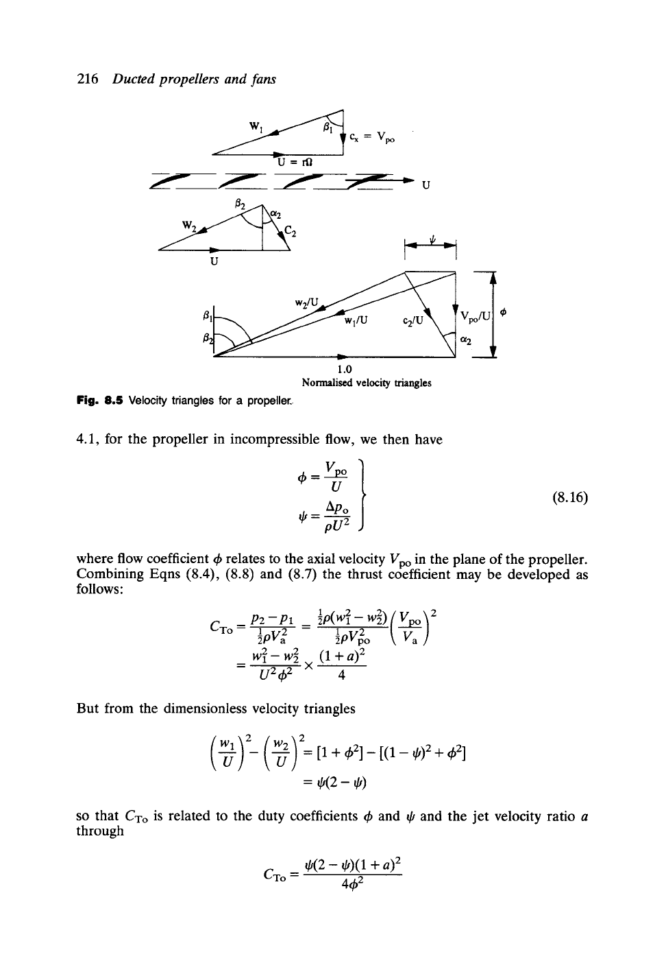
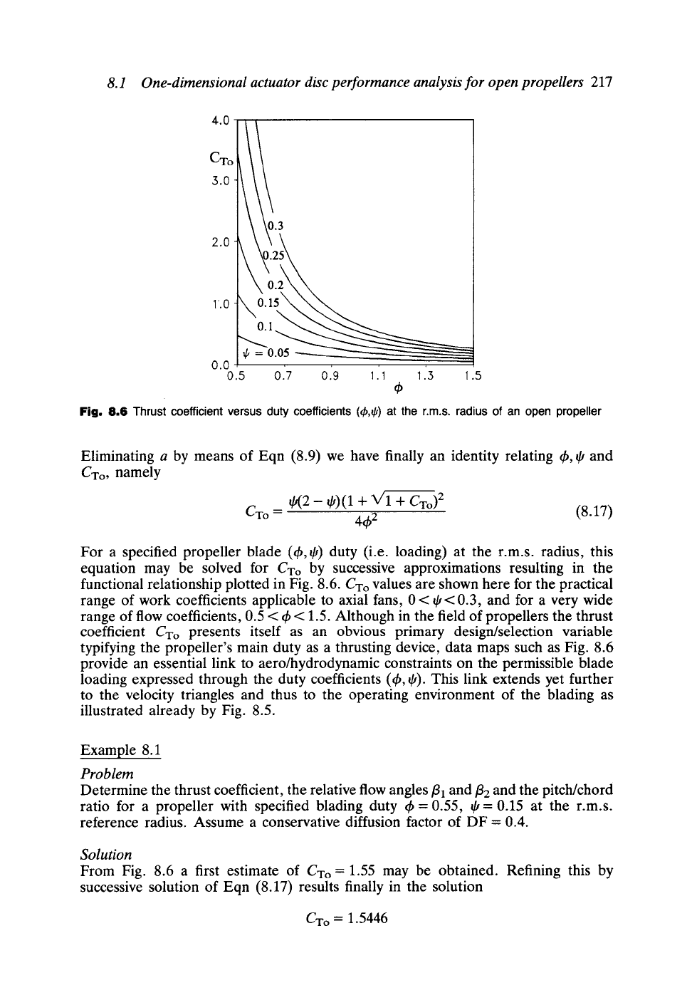
Fig, 8,6 Thrust coefficient
versus duty coefficients (~,~) at the r.m.s,
radius of an open
propeller
Eliminating a by means of Eqn (8.9) we have finally an identity relating th, ~ and
CTo, namely
~2- ~)(1 + ~/1 + CTo) 2
CTo = 4~b2 (8.17)
For a specified propeller blade (~b,~) duty (i.e. loading) at the r.m.s, radius, this
equation may be solved for CTo by successive approximations resulting in the
functional relationship plotted in Fig. 8.6. CTo values are shown here for the practical
range of work coefficients applicable to axial fans, 0 < ~ < 0.3, and for a very wide
range of flow coefficients, 0.5 < ~b < 1.5. Although in the field of propellers the thrust
coefficient CTo presents itself as an obvious primary design/selection variable
typifying the propeller's main duty as a thrusting device, data maps such as Fig. 8.6
provide an essential link to aero/hydrodynamic constraints on the permissible blade
loading expressed through the duty coefficients (~b, ~). This link extends yet further
to the velocity triangles and thus to the operating environment of the blading as
illustrated already by Fig. 8.5.
Example 8.1
Problem
Determine the thrust coefficient, the relative flow angles
fll
and
t2
and the pitch/chord
ratio for a propeller with specified blading duty th = 0.55, @= 0.15 at the r.m.s.
reference radius. Assume a conservative diffusion factor of DF = 0.4.
Solution
From Fig. 8.6 a first estimate of CTo = 1.55 may be obtained. Refining this by
successive solution of Eqn (8.17) results finally in the solution
CTo = 1.5446
218 Ducted propellers and fans
From velocity triangles we then have
fll --
arc tan (1/4)) = arc tan (1/0.55) = 61.189 ~
o8,)
/32 = arc tan 4) = arc tan \~ = 57.095 ~
From Section 4.7, Eqn (4.47a), by analogy with a high reaction axial fan, the
pitch/chord ratio is given by
_t = 2 {V,b 2 + (1 - @)2_ (1 - DF)V'4~ 2 + 1}
= 4.369
As might be expected, for this lightly loaded propeller (~, = 0.15), the pitch/chord
ratio is much higher than would be expected for a typical axial fan (see Example 4.4)
p. 104. We need to bear in mind that an open propeller does not have the benefit of a
surrounding duct or annulus which enables axial fan blades to generate lift from hub to
tip. Propeller blades must be designed to unload their aerodynamic lift forces
progressively to zero at the blade tips resulting in the shedding of helical vortices in the
tip region which also lead to additional induced drag. Some discussion of this will be
given in Section 8.4.1 but it is outside the present objectives and scope to provide
specific details of these complex fluid-dynamic design problems and their solution. A
wide variety of propeller blade design and profile selection methods to handle this are
covered in the literature, ranging from lifting line and lifting surface theories (Glover,
1970; Pien, 1961; Kerwin and Lee, 1978; Weissinger and Maass, 1968) to the cascade
strip method which is followed here in Chapters 2 and 4 based on turbomachinery
thinking. The objective at this point will be to turn our attention instead to a class of
propulsors much more akin to fans and pumps for which turbomachinery methodology
is more certainly applicable, namely ducted propeller systems.
8.2 Kort Nozzle and Pump Jet ducted propellers
The operating environment of a propeller may be modified considerably by locating it
within a surrounding annular duct which itself becomes an important component of
the propulsive system. As illustrated in Fig. 8.7 there are two types of ducted propulsor
which have been widely used, namely the Kort Nozzle and the Pump Jet. These have
quite different performance features and applications which are as follows.
The Kort Nozzle propulsor (Fig. 8.7(a)) has an accelerating duct designed to
increase the mass flow swallowing capacity of the propeller by raising the velocity
~p
in the propeller plane and therefore the jet momentum rhVj and total thrust. The
uct itself can provide a considerable proportion Td of the total thrust T = Tp + Td
of such propulsors, typically 25-30%. As will be shown later, an additional important
advantage of a Kort Nozzle propulsor is its capacity to develop much higher
propulsive efficiency than an open propeller of the same total thrust and to achieve
this with a smaller propeller diameter. Kort Nozzles are thus very attractive for the
propulsion of heavily loaded vehicles requiring good fuel economy and have
consequently been widely used for the propulsion of trawlers and tugs at the small
scale and also for supertankers and bulk carriers at the large scale where draft imposes
severe upper limits on propeller diameter. They also offer attractions for light
8.2 Kort Nozzle and Pump Jet ducted propellers 219
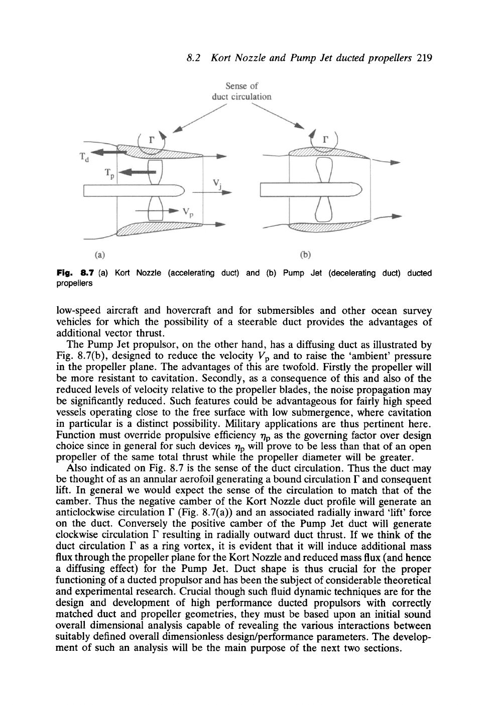
Fig. 8.7 (a) Kort Nozzle
(accelerating duct) and (b) Pump Jet
(decelerating duct) ducted
propellers
low-speed aircraft and hovercraft and for submersibles and other ocean survey
vehicles for which the possibility of a steerable duct provides the advantages of
additional vector thrust.
The Pump Jet propulsor, on the other hand, has a diffusing duct as illustrated by
Fig. 8.7(b), designed to reduce the velocity Vp and to raise the 'ambient' pressure
in the propeller plane. The advantages of this are twofold. Firstly the propeller will
be more resistant to cavitation. Secondly, as a consequence of this and also of the
reduced levels of velocity relative to the propeller blades, the noise propagation may
be significantly reduced. Such features could be advantageous for fairly high speed
vessels operating close to the free surface with low submergence, where cavitation
in particular is a distinct possibility. Military applications are thus pertinent here.
Function must override propulsive efficiency rip as the governing factor over design
choice since in general for such devices r/p will prove to be less than that of an open
propeller of the same total thrust while the propeller diameter will be greater.
Also indicated on Fig. 8.7 is the sense of the duct circulation. Thus the duct may
be thought of as an annular aerofoil generating a bound circulation F and consequent
lift. In general we would expect the sense of the circulation to match that of the
camber. Thus the negative camber of the Kort Nozzle duct profile will generate an
anticlockwise circulation F (Fig. 8.7(a)) and an associated radially inward 'lift' force
on the duct. Conversely the positive camber of the Pump Jet duct will generate
clockwise circulation F resulting in radially outward duct thrust. If we think of the
duct circulation F as a ring vortex, it is evident that it will induce additional mass
flux through the propeller plane for the Kort Nozzle and reduced mass flux (and hence
a diffusing effect) for the Pump Jet. Duct shape is thus crucial for the proper
functioning of a ducted propulsor and has been the subject of considerable theoretical
and experimental research. Crucial though such fluid dynamic techniques are for the
design and development of high performance ducted propulsors with correctly
matched duct and propeller geometries, they must be based upon an initial sound
overall dimensional analysis capable of revealing the various interactions between
suitably defined overall dimensionless design/performance parameters. Thedevelop-
ment of such an analysis will be the main purpose of the next two sections.
220 Ducted propellers and fans
8.3 Dimensional analysis for ducted propellers
Following similar arguments the analysis in Section 8.1 may be extended to ducted
propellers for which the total thrust may be expressed as
,.trD 2
T= p---~--Vp(Vj- Va) (8.18)
= Tp+Td
In this case it is convenient to define an additional dimensionless variable to account
for the duct thrust, namely the thrust ratio ~':
T'--
Propeller thrust = Tp (8.19)
Total thrust T
As before, Eqn (8.4), the propeller thrust Tp may be related to jet velocity Vj by
applying Bernoulli's equation to yield
,trD 2 p,a.D 2
Tp = (P2 - Pl) 4 = ~ (v2 - v2) (8.20)
= ~-T
Eliminating T from Eqns (8.18) and (8.20) results in the following expression for the
velocity Vp in the propeller plane:
Va + Vj
(8.21)
Vp= 2r
Comparing this with the analogous result for open propellers, Eqn (8.7), we note
that the thrust ratio ~-influences Vp as shown in Table 8.1.
Table 8.1 Effect of duct thrust on velocity Vp in the plane of a ducted propeller
Duct thrust Thrust ratio Type of ducted Comparison with
Tp r propeller equivalent open
propeller
Positive ~- < 1.0 Kort Nozzle Vp > Vpo
Zero r= 1.0 Open propeller Vp = Vpo
Negative z > 1.0 Pump Jet Vp < Vpo
The thrust ratio ~-thus has a profound effect upon the velocity level in the propeller
plane and unequivocally determines whether a ducted propulsor is a Kort Nozzle
(r< 1.0) or a Pump Jet (~'> 1.0).
The propulsive efficiency for an open propeller was shown to be a function of the
thrust coefficient CTo only, Eqn (8.15). For a ducted propulsor, on the other hand,
8.3 Dimensional analysis for ducted propellers
221
adopting the same basic definition of propulsive efficiency, Eqn (8.11), we would
expect r/p to exhibit the following general form of relationship:
np= f(CT, r)
(8.22)
where both CT and z can now be regarded as the available overall independent
design variables. By analysis similar to that in Section 8.1 this general equation
may be transformed into an explicit form which determines quite definitively the
influence of both CT and r upon r/p. To achieve this the thrust coefficient may first
be expressed as
CT
Te + Td
1
2 7rD2
"~pVa 4
1{ }
- -z pV2a rtD2
4
(8.23)
Introducing Tp from Eqn (8.20) then yields
1 2
CT
which may be inverted to reveal the dependency of the jet velocity
Vj/Va
upon the
independent design variables CT and z, namely
Vj = V'I + rCT (8.24)
Va
Now as already suggested, the previous definition of propulsive efficiency for open
propellers, Eqn (8.11), is no less valid here for ducted propellers, namely
Propulsive power delivered to vehicle, P P
= [8.11]
l"/p --
Shaft input power, Ps P + Ew
where, making use of Eqn (8.20), the propulsive power P is given by
P = Thrust x vehicle speed
= TV a
= PrrD.__~ 2 (V 2 - V2a)V
a
8r
(8.25)
The wake kinetic energy loss Ew, making use also of Eqns (8.2) and (8.21),
becomes
EW
1 rh(Vj- Va) 2 1 7rD 2 Vp(Vj-
Va) 2
_ P~D 2
- 16---~ (Vj-
Va)2(Va + Vj)
(8.26)
222
Ducted propellers and fans
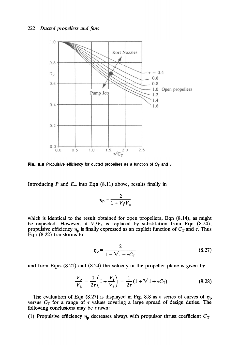
Fig. 8.8 Propulsive efficiency for ducted propellers as a function of
C T
and ~-
Introducing P and Ew into Eqn (8.11) above, results finally in
~p --
1
+ Vj/V a
which is identical to the result obtained for open propellers, Eqn (8.14), as might
be expected. However, if
Vj/Va
is replaced by substitution from Eqn (8.24),
propulsive efficiency r/p is finally expressed as an explicit function of CT and r. Thus
Eqn (8.22) transforms to
2
"tiP
=
1 + V'I + rCT
(8.27)
and from Eqns (8.21) and (8.24) the velocity in the propeller plane is given by
1
V =-~r I+V~ =:~-~(1
+ V' 1 + ~'CT) (8.28)
The evaluation of Eqn (8.27) is displayed in Fig. 8.8 as a series of curves of r/p
versus
Cx
for a range of 9 values coveting a large spread of design duties. The
following conclusions may be drawn"
(1) Propulsive efficiency
l?p
decreases always with propulsor thrust coefficient CT
(2)
(3)
(4)
8.3 Dimensional analysis for ducted propellers
223
as would be expected due to the increased jet velocity Vj and the consequent
wake kinetic energy dissipation Ew.
For a given design choice of CT the propulsive efficiency will be increased by
selection of thrust ratio in the range z< 1.0, corresponding to a Kort Nozzle.
Conversely, for a given design choice of CT, the propulsive efficiency will be
reduced if a Pump Jet duct is chosen for which z > 1.0.
The open propeller corresponds to the situation r = 1.0 for which there
would be zero duct thrust so that there would be little point in retaining the
duct.
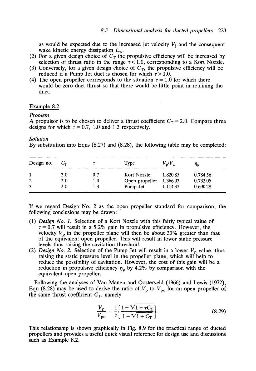
Example 8.2
Problem
A propulsor is to be chosen to deliver a thrust coefficient CT = 2.0. Compare three
designs for which r = 0.7, 1.0 and 1.3 respectively.
Solution
By substitution into Eqns (8.27) and (8.28), the following table may be completed:
Design no. CT r Type
Vp/Va "qp
1 2.0 0.7 Kort Nozzle 1.820 85 0.784 56
2 2.0 1.0 Open propeller 1.366 03 0.732 05
3 2.0 1.3 Pump Jet 1.114 37 0.690 28
If we regard Design No. 2 as the open propeller standard for comparison, the
following conclusions may be drawn:
(1)
(2)
Design No. 1.
Selection of a Kort Nozzle with this fairly typical value of
z = 0.7 will result in a 5.2% gain in propulsive efficiency. However, the
velocity Vp in the propeller plane will then be about 33% greater than that
of the equivalent open propeller. This will result in lower static pressure
levels thus raising the cavitation threshold.
Design No. 2.
Selection of the Pump Jet will result in a lower Vp value, thus
raising the static pressure level in the propeller plane, which will help to
reduce the possibility of cavitation. However, the cost of this gain will be a
reduction in propulsive efficiency r/p by 4.2% by comparison with the
equivalent open propeller.
Following the analyses of Van Manen and Oosterveld (1966) and Lewis (1972),
Eqn (8.28) may be used to derive the ratio of Vp to Vpo for an open propeller of
the same thrust coefficient CT, namely
Vp
_-1{1+_ V'I+~Cx].. - (8.29)
Vpo z 1+ X/l+ CT
This relationship is shown graphically in Fig. 8.9 for the practical range of ducted
propellers and provides a useful quick visual reference for design use and discussions
such as Example 8.2.