Kutz M. Handbook of materials selection
Подождите немного. Документ загружается.

3 CREEP AND STRESS RELAXATION TESTING 527
time
strain or elongation
low stress
(or low temp)
high stress
(or high temp)
stage I
stage II
stage III
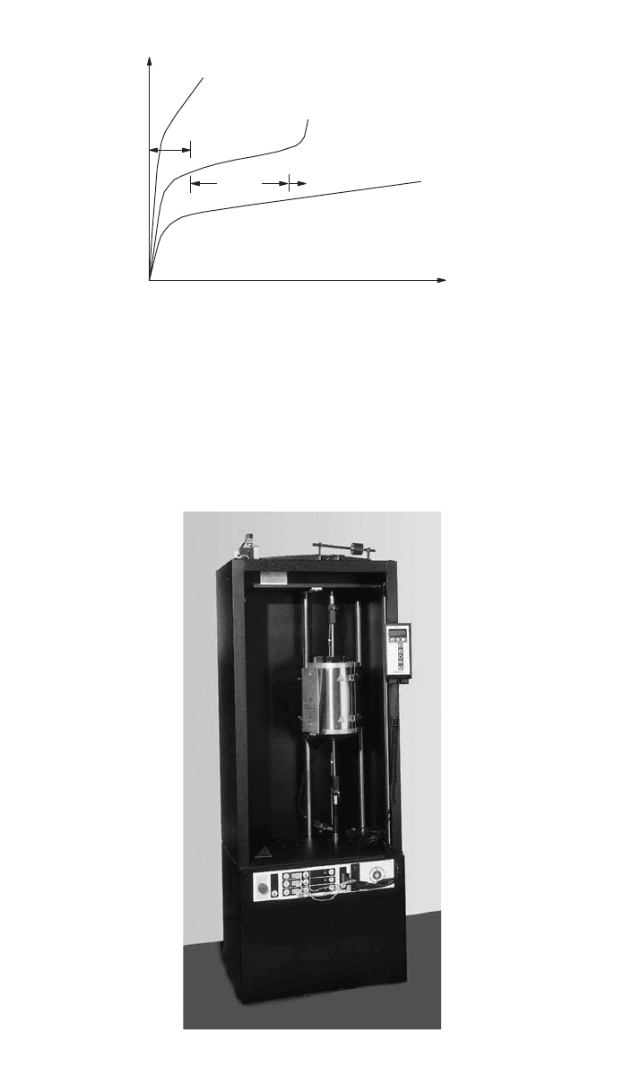
Fig. 6 Schematic of the different regions of a classic creep curve.
Fig. 7 Loading frame to apply static (or extremely slow cyclic) load conditions.
(Courtesy of the Instron Corporation)

528 TESTING OF METALLIC MATERIALS
extensometry as used in tensile tests can be used on the specimen. However,
higher temperatures are usually involved for most metals, which necessitates
using LVDT, capacitive, or other types of displacement measurement transduc-
ers. The most common transducer is the LVDT coupled with linkages that reach
up through the furnace to attach to the specimen. Special care must subsequently
be taken to ensure that the displacements measured actually correspond to gauge
length deformation and are not biased by linkage or transducer effects.
Stress relaxation testing (ASTM E328) is similar in many ways to creep
testing except that the applied boundary condition is a constant displacement (as
opposed to a constant load). This type of test is more suitable for metallic
materials that have significant constraint and hence exhibit little strain increase
as a function of time. One example of this is a high-temperature bolted joint
where a displacement boundary condition is first applied and then the stress
relaxes with time. Testing times include both long-term (months or more) at the
service temperature and accelerated tests (days) at more aggressive thermal con-
ditions.
Creep and stress relaxation testing can also be performed on specimens with
a more complex stress state than simple tension. Examples include compression
testing (typically using a carefully machined cylindrical specimen similar to that
described earlier for quasi-static compression testing), bend testing (e.g., with a
cantilever beam specimen), or even torsion testing. Testing has also been per-
formed on tubular specimens that are subject to complex, multiaxial stress states.
4 HARDNESS AND IMPACT TESTING
This section addresses two mechanical test methods that are used to indirectly
determine the tensile and toughness properties of a metallic material. As with
any indirect test method, there are well-known limitations to these techniques,
but they are clearly offset by the reduced cost and increased efficiency of the
indirect methods. The test methods, as well as their limitations, will be explained
in more detail in this section.
Hardness refers to a material’s ability to resist deformation when loaded by
an indenter. The indenter can differ in geometry; for instance, it can be conical
(the Rockwell test), spherical (Brinell), or pyramidal (Vickers and Knoop). For
metallic materials, hardness is directly proportional to the yield stress of the
material. Nevertheless, conversions are readily available to relate hardness to
ultimate tensile strength (most commonly for steel although other conversions
for different metallic materials do exist). Hardness testing (ASTM E6, E10, E18,
E92, E1842, and others) is industrially attractive since the testing is rapid (
⬍20
s), low cost, nondestructive, and generally does not require a machined speci-
men. As a consequence of these issues, hardness is often used as an industrial
screening tool to ensure metallic material processing control. An ASTM standard
(E140) exists to convert between the different superficial hardness and conven-
tional hardness scales.
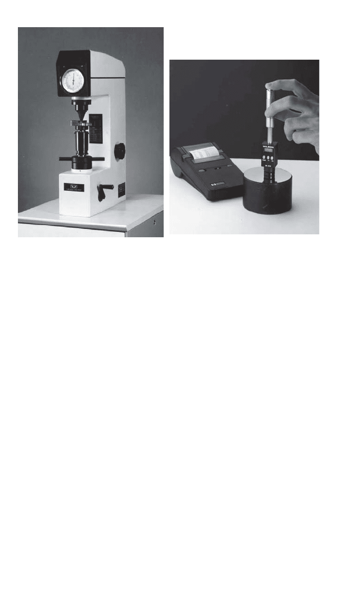
The majority of hardness testers (e.g., those shown in Fig. 8) utilize dead-
weight, springs, or (infrequently) closed-loop computerized systems. Although
many testers provide output on an analog meter, bench-top units with digital
readouts (sometimes with an interface for a PC) are generally more popular
today. When the component being hardness tested is too large to practically
4 HARDNESS AND IMPACT TESTING 529
(a) (b)
Fig. 8 Hardness testers including (a) a benchtop and (b) portable unit.
(Courtesy of the Instron Corporation)
position onto the anvil of the tester, portable test units are available to locally
measure hardness. A typical portable hardness measurer is shown in Fig. 8b.
Regardless of the type of hardness tester used, care must be taken to ensure that
the system is in proper working order by using commercially available calibra-
tion blocks.
Although hardness testing is relatively simple, accurate measurements depend
greatly on careful attention to detail. The anvil should minimize the contact area
with the component. Surface finish can sometimes be of paramount concern; for
100–150 kgf, a finish ground surface is sufficient whereas for a 15-kgf load, a
polished or lapped surface usually is required. Surfaces that are ridged due to
machining or that exhibit loose, flaking scale can yield incorrect hardness results.
The test surface should be perpendicular to the indenter since even slight (
⬍5⬚)
angular deviation can cause hardness to shift by several points. Indenter size
should be chosen with the underlying grain structure of the metallic material in
mind. In general, the indenter should be larger than the grain size if a macro-
scopic measurement of hardness is desired. Finally, metallic material homo-
geneity is also important since the indenter effectively samples a region
approximately 10 times deeper than the depth of the indenter penetration.
Instrumented indentation testing is a more recent method developed to derive
more extensive data from effectively a hardness test. During this type of testing,
the instantaneous load–displacement data is recorded continuously. The mea-
sured data can be related to such things as elastic modulus, yield strength, and
strain hardening exponent. Highly empirical punch test methods are also contin-
ually evolving to relate local deformation behavior to properties such as fracture
toughness.
530 TESTING OF METALLIC MATERIALS
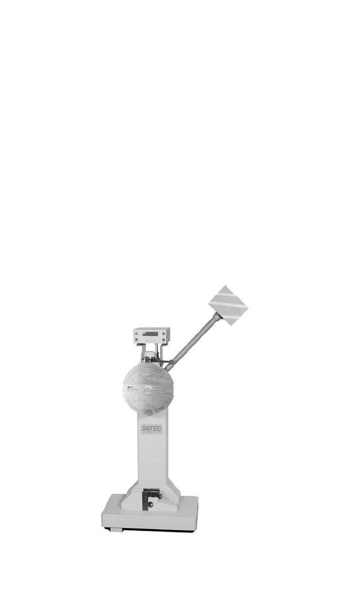
Fig. 9 Example of a pendulum impact machine. (Courtesy of the Instron Corporation)
Since some percentage of loading is inevitably dynamic and components often
have to be designed to survive high loading rates typical during an accident,
dynamic fracture testing can ensure structural integrity under this type of load-
ing. During impact testing, a pendulum machine (example shown in Fig. 9) with
a striker is typically used to impart high energy to a notched sample. The notch
toughness of the specimen, typically a flat bar with a carefully machined notch
of various geometries, is measured in terms of the absorbed impact energy that
causes fracture in the specimen. Some other parameters that are commonly ex-
amined include fracture appearance and the deformation noted on the surface of
the specimen. The independent variable controlled during testing is most often
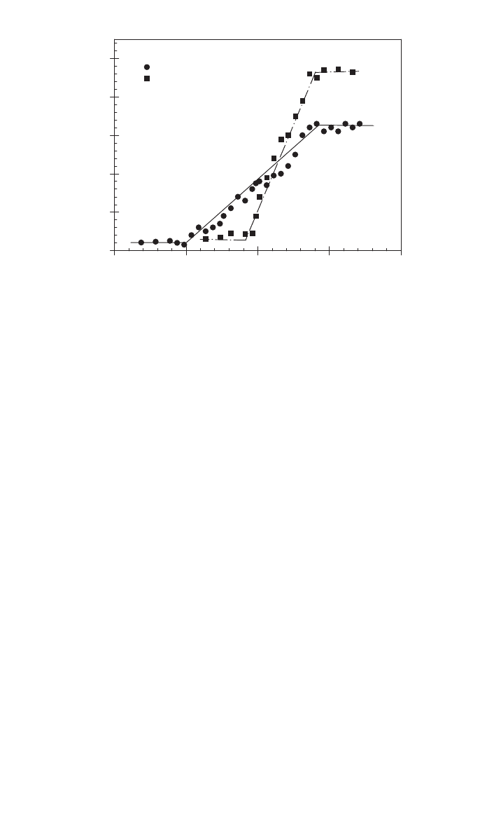
temperature. A typical energy–temperature curve for A36 steel is shown in Fig.
10 contrasting the typical difference between slow bend tests and rapid impact
results.
The Charpy and Izod impact tests both utilize pendulum loading albeit with
specimens of slightly different geometry, especially as related to the specimen
notch dimensions. The primary difference between the two tests though is that
the Charpy V-notch (CVN test as defined in ASTM E23) specimen is three-
point loaded whereas the Izod specimen is cantilever loaded.* Of the two meth-
ods, the CVN test remains the most popular method available, and manufacturing
*Both machines were developed in the beginning of the twentieth century although Charpy was a
Frenchman and Izod was an Englishman.
5 FRACTURE TOUGHNESS TESTING 531
A36 steel
Temperature, F
-400 -200 0 200 400
Absorbed Energy, ft-lb
0
10
20
30
40
50
slow bend
impact (CVN)
upper shelf
lower shelf
Fig. 10 Impact test results illustrating CVN energy versus temperature curves for A36 steel.
lot release requirements using CVN data are actually written into many metallic
material specifications. The CVN test is rapid and low cost; the most expensive
part is machining specimens although commercial machining templates to ease
fabrication are readily available.
Two other impact tests include the drop-weight (ASTM E208) and the drop-
weight tear test (DWTT as per E436). During drop-weight tests, a series of
experiments are performed where different specimens at a range of temperatures
are impacted with a guided, free-falling weight dropped from a fixed height.
The key finding is the nil-ductility transition temperature (NDTT), which is the
maximum temperature where fracture was observed. The DWTT test is similar
to the drop-weight test although the specimen used is slightly larger and the test
fixturing is very different. The fracture surfaces are evaluated and the percentage
of shear quantified. The temperature at which 50% shear occurs is loosely de-
fined as the ductile-to-brittle transition temperature.
CVN testing can also be performed with a fatigue precracked specimen to
eliminate the notch acuity and depth restrictions inherent to the standard CVN
specimen geometry. Considerable effort has also been recently expended devel-
oping instrumented impact testers to record more data. Nevertheless, the primary
shortfall with most of the impact test methods is (a) the relatively small specimen
size (relative to component size) and (b) the high degree of empiricism used to
relate the results to metallic material properties. These disadvantages are offset
by the simplicity and low cost of the test, particularly for production environ-
ments where the test can be used effectively as a quality control tool.
5 FRACTURE TOUGHNESS TESTING
The foregoing discussion introduced the concept of notch toughness, defined
loosely as the energy required to initiate a running fracture from a machined
notch. This is an important design parameter since nearly all structures contain
notchlike stress concentrations. However, in the strictest sense according to the

532 TESTING OF METALLIC MATERIALS
science of fracture mechanics (the study of cracks), fracture is broadly classified
as either brittle [governed by linear elastic fracture mechanics concepts (LEFM)]
or ductile [elastic plastic fracture mechanics (EPFM)]. Fracture toughness is the
ability of a material to withstand unstable crack propagation (e.g., fracture) as-
suming of course the presence of a crack. Fracture mechanics provides the the-
oretical underpinning that relates the following quantities:
●
Magnitude and range of the remote applied stress
●
Geometry of the component
●
Morphology (size and shape) of the crack
to what is loosely termed the ‘‘crack driving force,’’ or stress–intensity factor
K. Detailed stress analyses of cracks have shown that the magnitude of the local
crack-tip stress field is proportional to this K parameter. Although K applies for
LEFM, in the case of EPFM there exists another similitude parameter that is
termed J.
Fracture toughness testing requires closed-loop, computer-controlled servo-
hydraulic test equipment and a suite of accurate displacement extensometers.
Virtually all tests are computer controlled due to the complexity of the test and
the requirements for recorded data. As a minimum, most fracture tests require
measuring the applied load and some displacement measurement across the
crack. Most tests are analyzed by custom software developed specifically for the
particular test. The most common fracture toughness test is the plane-strain frac-
ture toughness measurement, which yields the K
Ic
parameter as described in
detail in ASTM E399. For an ASTM valid K
Ic
value, the loading must be such
that there is no significant plastic deformation (specifically, the plastic zone at
the tip of the crack is less than 2% of the thickness and total crack length). The
plane-strain requirement implies that the fracture toughness specimens tend to
be quite thick, most are commonly greater than 0.5 in.
Although E399 allows a variety of specimens, the most commonly used is
the compact-tension specimen, a pin-loaded, edge-notched geometry. The spec-
imen is first precracked under fatigue loading to ensure that the crack tip is
sufficiently sharp for the fracture test. The specimen is then loaded to failure by
a constant displacement ramp applied between the pins. During the test, the load
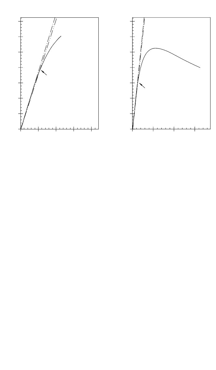
and crack mouth opening displacement (CMOD) is measured. Two sample load –
displacement plots are shown in Fig. 11. In Fig. 11a, the behavior is more brittle
with catastrophic failure at peak load. Conversely, in Fig. 11b the trend is more
suggestive of a ductile and somewhat more stable material with slow crack
advance gradually relieving load as the test progresses past the point of maxi-
mum load.
Determining a K
Ic
toughness from the load–CMOD data requires fitting the
initial linear portion of the data and plotting a 5% secant offset to that linear
region. The intersection between the measured load–CMOD data and this secant
line defines the critical load. This graphical construction is evident in Fig. 11a.
However there are stringent limits for qualifying the conditional K
q
toughness
as an ASTM-valid K
Ic
. Most importantly, the crack length and thickness are
required to be sufficiently long to satisfy the small-scale yielding criteria de-
5 FRACTURE TOUGHNESS TESTING 533
(a)
Load, kips
Load, kips
(b)
Temp =
1050°F
Material =
beryllium
q
K =
19 ksi 公in
CMOD displacement, 10
–3
inch
0204060
0
1
2
3
4
5
6
7
linear fit
of data
5% slope
offset
0
1
2
3
4
5
6
7
P
q
Material
=
beryllium
Temp =
800°F
K
q
CMOD displacement, 10
–3
inch
0 5 10 15 20
25 ksi 公in
=
P
q
Fig. 11 Two load–displacement plots from K
Ic
fracture toughness tests conducted
on beryllium at elevated temperature.
scribed earlier. Furthermore, nonlinearity is minimized by requiring that the crit-
ical load (corresponding to K
q
and denoted by P
q
) must be no less than 90% of
the maximum measured load. The two sets of data indicated in Fig. 11 are clearly
invalid since the conditional P
q
load is too low relative to the maximum mea-
sured load.
Whereas K
Ic
applies for thicker, more constrained sections where catastrophic
fracture occurs rapidly, a different K
C
fracture test (ASTM E561, also termed a
K–R curve) applies for thinner structure where slow stable crack extension pre-
cedes unstable fracture. The test specimen geometry typically used is a wide,
center cracked panel precracked at low loads to generate a sharp fatigue crack
suitable for fracture. The specimen is monotonically displaced similar to a K
Ic
specimen while recording load, CMOD, and often some parameter such as elec-
tric potential drop that can be used to instantaneously provide crack length mea-
surement.
The resistance curve, also called an R curve, is then generated by plotting
crack driving force K against crack extension, termed
⌬a. Crack extension is
defined as the sum of the physical crack length change, usually derived from
either compliance (stiffness) or some other nonvisual crack length indicator, plus
the half plastic zone size. Since the stress state is typically something more like
plane stress, the plastic zones as observed on the surface of the specimen tend
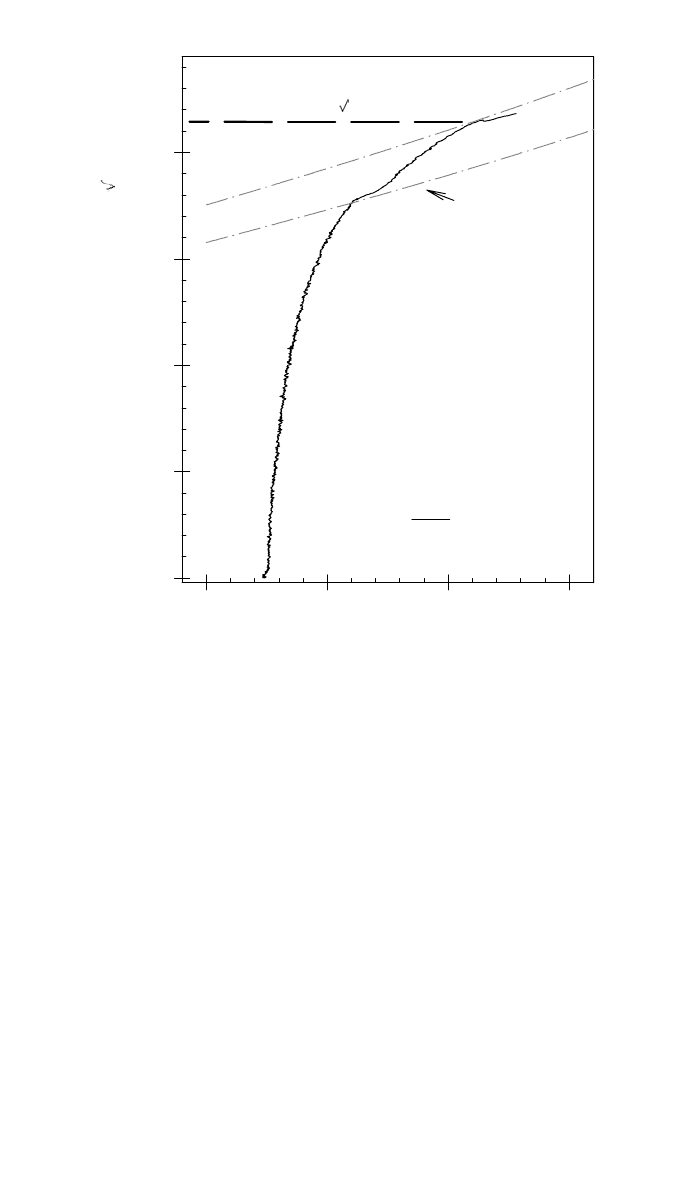
to be quite large. An example R curve is shown in Fig. 12. The K
C
value is
defined as the K magnitude at the tangent intersection between the R curve and
lines of constant load plotted in K versus crack length (or crack length extension)
space. This load represents the maximum level that can be achieved before the
crack extends (often unstably) and structural integrity is lost. A careful exami-
534 TESTING OF METALLIC MATERIALS
stainless steel
Width normalized effective crack length, 2a
e
/W
0.35 0.40 0.45 0.50
Crack growth resistance, K
R
ksi
in
0
50
100
150
200
recorded data
61.2 kip
applied K curves
for different fixed
load values
K
c
= 215.2 ksi
in
55.0 kip
Fig. 12 Example R curve from a K
C
fracture toughness test performed on stainless steel.
nation of the data in Fig. 12 clearly illustrates that some crack growth was
apparent in this metallic material since catastrophic failure did not occur at the
point of instability.
Fracture toughness testing in the elastic-plastic regime is time consuming, not
trivial, and requires advanced instrumentation to yield excellent results.
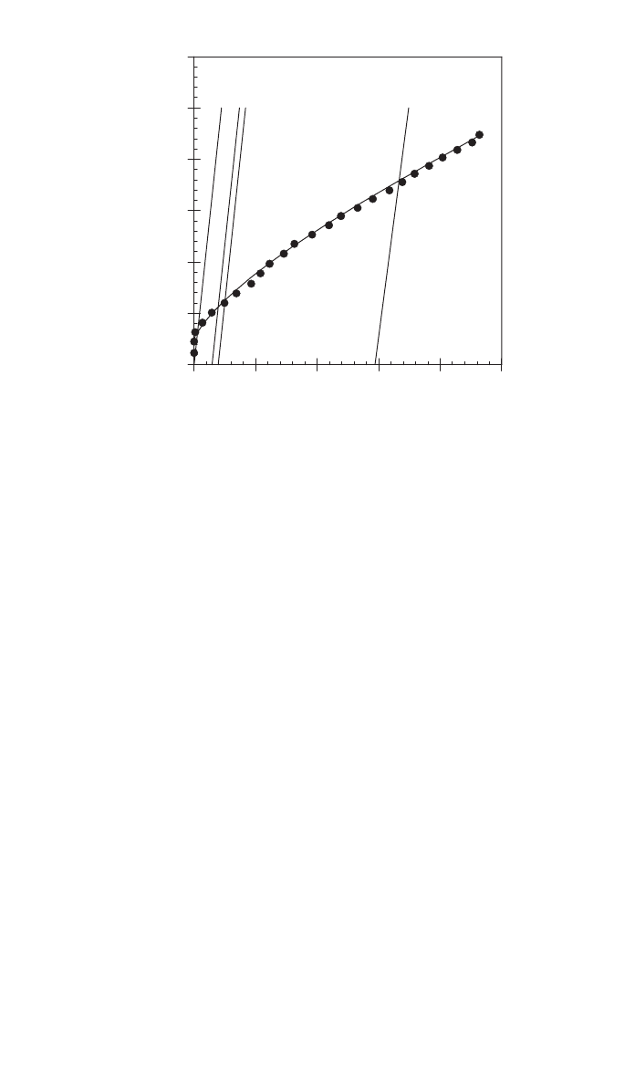
7
After
conducting and analyzing the test, the goal is to generate an R curve, similar to
that described earlier for the K
C
testing, as shown in Fig. 13. However, instead
of K on the abscissa, the J parameter is included. The J parameter is calculated
by including an elastic portion related to K combined with a nonlinear portion
related to the area under the load–displacement curve (with respect to load-line
displacement). The plane-strain, elastic plastic J
Ic
parameter measures the onset
of instability, in this case corresponding to the point where the crack has ad-
vanced a certain amount (after blunting) on the R curve (note this instability
criteria is very different than that described for K
C
). It is often the case in this
type of test that slow, stable cracking will continue as the specimen is displaced
and the load gradually drops to a small fraction of the peak obtained.
The J
Ic
test procedure is usually performed using compact-tension specimens,
although three-point bend specimens are also possible provided care is taken to
ensure that accurate instrumentation is available to measure load-line displace-
6 FATIGUE TESTING 535
Inconel HAZ
W=1.0 inch, B=0.5 inch
Crack length extension, 10
–3
inch
0 20406080100
Fracture Resistance, J in-lb/in
2
Ic
0
400
800
1200
1600
2000
2400
Fig. 13 Example of an R curve from a J
Ic
fracture toughness test performed
on a high-strength weld.
ment. The primary challenge with J
Ic
testing is the high accuracy required from
measurements of the load-line displacement. High-resolution measurement is
required so as to infer the extremely small amount of crack tearing necessary
for the J
Ic
fracture toughness definition. This high accuracy is practically
achieved through higher accuracy (minimum of 16 bit), low noise data acqui-
sition boards combined with extreme care and control over the critical test de-
tails, especially as related to loading pin interfaces and clip gauge attachment.
In editions of the ASTM test standards prior to 1998, the test method for the
elastic-plastic J
Ic
parameter has always been described in ASTM E813. However,
the E08 committee of ASTM has recently published a combined approach under
the designation E1820. This combined approach outlines a procedure to follow
that can result in any one of the primary toughness parameters, namely K
Ic
, K-,
and J-resistance curves. Although these three parameters constitute the most
common fracture test standards, other ASTM methods are also available:
●
Crack-tip opening displacement (CTOD) fracture toughness (E1290)
●
Plane-strain crack arrest fracture toughness (E1221)
●
Fracture testing with surface-crack tension specimens (E740)
●
Chevron notch fracture toughness of metallic materials (E1304)
However, these methods are typically not as wide-ranging nor as commonly
encountered in design as the previously noted fracture toughness test methods.
6 FATIGUE TESTING
The previous section described basic fracture mechanics concepts as well as the
test methods used to quantify fracture behavior given a preexisting crack. In this

536 TESTING OF METALLIC MATERIALS
section the process of crack nucleation (e.g., crack initiation) and stable propa-
gation (e.g., crack growth) under cyclic loading is addressed. Understanding
crack propagation behavior is critically important since some structures, most
notably the current fleet of commercial airliners, adopt a damage tolerance de-
sign philosophy whereby cracks are assumed in the structure, and a safe struc-
tural life requires detecting and managing these cracks. Quantifying crack
nucleation is also important since much of a crack’s cyclic life is spent initiating
or growing when it is small in size.
The test specimens used for fatigue crack initiation testing are similar geo-
metrically to tensile specimens. The two basic test methods for initiation testing
are ASTM E606 and E466 for strain- and stress-controlled testing, respectively.
With both of these methods, the goal is to cycle a specimen until failure occurs.
Strain control is typically used if (a) the loading is with a constant displacement
or (b) the focus is on the short life regime (estimated to be less than 10
3
to 10
5
cycles although this is fairly controversial) where applied stress levels often
approach the yield strength of the metallic material. Conversely load control
testing is performed for the mid- to high-cycle life regime. Stress (effectively
load) control testing is relatively straightforward since no displacement moni-
toring or measurement is required. The specimen can be gripped, cycling can
commence, and continue unmonitored (provided the servocontrol loop does not
require any attention) until failure occurs.
One of the most critical details when performing this type of fatigue testing
is controlling bending in the specimen. Poor control of bending typically in-
creases the apparent scatter in the fatigue data generated. Commercial alignment
fixtures are available to mitigate bending. These fixtures utilize a strain gauged
specimen and a fixture that allows minute adjustments of the loading train. How-
ever, these fixtures are not always available, which means less high tech and
pragmatic methods are often required to minimize the effect.
Although guidelines on how to measure and verify specimen alignment are
provided in ASTM E1012, minimizing bending practically requires control of
three issues. First, the specimen must be carefully machined with excellent di-
mensional control, parallelism, and axisymmetry. Second, the fixtures used to
connect the specimen to the loading train must not introduce any asymmetry.
Threaded specimen ends, although commonly employed during fatigue testing,
should be avoided as the tolerances required to engage the thread make accurate
alignment problematic (however, it must be stated that it is not always practical
or possible to avoid threaded ends). If the loading cycle is tensile only (e.g., a
positive R ratio where R is the ratio of minimum to maximum load), a spherical
joint, or more commonly known as a U-joint, in the loading train can minimize
bending. Third, the fixtures in the load train should be designed well enough to
grip repeatably in the same manner so that once a load train has been carefully
aligned with an instrumented specimen it does not vary.
Some typical stress–life (S–N) data are shown in Fig. 14 for two materials,
an aluminum and titanium alloy. S–N data are usually generated at a fixed R
ratio with the results represented as a plot with stress amplitude or maximum
stress on the abscissa and cyclic life on the ordinate. Data are sometimes gen-
erated on specimens that have a groove or hole to simulate stress concentrations
typically found in structure. Furthermore, it is often of practical interest to know
