Kuppan T. Heat Exchanger Design Handbook
Подождите немного. Документ загружается.

564
Chapter
I1
The load deflection relations for short shell and annular plate elements to assemble the
stiffness equations are derived
in
their work. They are not repeated here. Most of the formulas
that are part of the TEMA procedure are arrived at after substituting
n
=
0.3
in the formulas of
Singh and Soler [41] model.
Procedure for Design of Formed Head Expansion Joints
Rules for designing the formed head expansion joint currently exist in TEMA, ASME Code
Section VIII, Div.
1,
ANCC VSRlP, and A. D. Merkblatter, among others. HEDH [34] sum-
marizes the salient features of flanged and flued type expansion joint design.
TEMA Procedure.
The seventh edition
(1988)
of the TEMA Standards includes a new section
RCB-8 on flexible shell elements (not light-gauge bellows type expansion joints), to be used
in
conjunction with fixed tube-sheet design. The paragraph encompasses several different
shapes, such as flanged and flued heads, flanged only heads, and others. Also included is a
method to calculate the maximum stress for cycle life calculations. The shell flexible elements
shall be analyzed
in
both corroded and uncorroded conditions and shall be evaluated for hydro-
static test conditions also.
Minimum Thickness.
As per TEMA RCB-8.9, the minimum thickness of the flexible shell
elements shall be determined by the method of analysis. However, in no case shall the mini-
mum uncorroded thickness be less than 3.2 mm (0.125
in)
for nominal diameters up to
18
in,
4.8 mm (3/16
in)
for nominal diameters in the range of
19-30
in (482.6-762 mm), or
6.35
mm (0.25
in)
for nominal diameter greater than
30
in
(762 mm). The industry practice is to
set the FSE thickness one gauge less than the shell thickness [41]. When required, use more
than one set of formed heads.
Allowable Stress (TEMA RCB-8.8).
The allowable stresses
in
the flexible element, both
in
the corroded and uncorroded conditions, shall be as defined in the ASME Code using an
appropriate stress concentration factor for the geometry.
Design Procedure as Per ASME Code
ASME Code Section VIII, Div.
1,
does not give formulas for sizing the formed head expansion
joints. However, rules are given for materials of construction, stress limits, cycle life calcula-
tion, fabrication, inspection and pressure test, stamping, and reports. The design of expansion
joints shall conform to the requirements of Appendix CC of the ASME Code. Design aspects
of multilayer, asymmetric geometries or loadings that differ from the basic concepts of Appen-
dix CC are dealt in Paragraph U-2(g). Details of fabrication and inspection of formed type
expansion joints are covered
in
Chapter
15,
Heat Exchanger Fabrication. Stamping details are
covered here.
Construction Materials and Minimum Thickness.
According to ASME Code Section VIII,
Div.
1,
the materials for pressure retaining components shall conform to the requirements of
UG-4. For thick-wall formed heads type expansion joints,
in
general, the bellows are
of
the
same material as the shell.
Stamping and Reports.
Details of stamping and reports are outlined
in
Section CC-6.
As
per
this section, the expansion joint manufacturer shall have a valid ASME Code
U
certification
of authorization and shall complete a Form U-2 Manufacturer’s Partial Data Report, as required
by UG- 120(c). The Manufacturer’s Partial Data Report shall contain data and information like:
Mechanical Design
of
Heat Exchangers
565
1.
Maximum allowable working pressure and temperature
2.
Spring rate and axial movement
3.
Service conditions
4.
Design life in cycles
5.
A
certification that the expansion joint has been constructed as per the rules of Appen-
dix CC
6.
Details of the vessel manufacturer
6.4
Design
of
Bellows or Formed Membranes
Bellow type expansion joint design shall conform to the requirements
of
EJMA Standards, the
ANSI Piping Codes, and the ASME Codes as applicable. The design
of
structural attachment
shall be in accordance with accepted methods, based on elastic theory. In addition to EJMA
Standards, design analysis and rules are
also
included in Appendix
BB,
ASME Code Section
VIII, Div. 1, for circular type bellows with single-ply reinforced and nonreinforced bellows
with thickness less than
3.2
mm
(0.125
in).
Shapes and Cross Section
The bellows are available both for circular shells and rectangular shells. Rectangular shapes
are used for surface condensers.
Bellows Materials
The bellows material shall be specified and must be compatible with the fluid handled, the
external environment, and the operating temperature. Particular consideration shall be given to
possible corrosion attack.
Bellows Design-Circular Expansion Joints
The design of bellows type expansion joints involves an evaluation of pressure-retaining capac-
ity, stress due to deflection, spring rate, fatigue life, and instability (squirm). The spring rate
is a function of the dimensions
of
the bellows and the bellows material. The determination
of
an acceptable design further involves the bellows parameters such as material, diameter, thick-
ness, number of convolutions, pitch, height, number of plies, method of reinforcement, manu-
facturing technique, and heat treatment.
Limitations and Means to Improve the Operational Capability of Bellows
Single-ply bellows are used for low-pressure applications. They are fragile and hence they are
easily damaged; external covers to protect personnel against the hazards of bellows blow-out
due
to
failure are necessary. Drainable varieties are expensive, and external supports may be
required to maintain alignment of the shell sections welded to the expansion joint
[29].
Addi-
tionally, single-ply bellows are susceptible to instability. Since a bellows is a thin shell
of
revolution with repeated U-shaped convolutions, there exists a large number of natural vibra-
tion modes. Basically, these vibration modes are classified into three types: axial accordion
modes, lateral bending modes, and shell modes, among which the former two are easily excited
[93].
Methods and improved designs
to
overcome various shortcomings are discussed in the
EJMA Standards. The following measures are normally adopted by designers to improve the
single-ply expansion joint:
1.
Use of external reinforcement
2.
Use of multi-ply construction and thicker convolutions
3.
Pressure balanced expansion joints
566
Chapter
1
I
REIN
FORCING RINGS
END
EQUALIZING
0.0.
ot
cylindrical
tangent
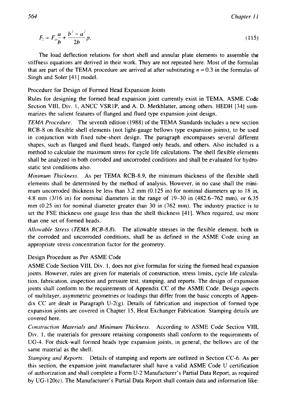
Figure
25
External reinforcement for bellows. (From Ref.
8.)
4.
Flow sleeve inside the convolutions
External Reinforcement.
A
combination of high internal pressure-retaining capacity and large
deflection can be achieved by external reinforcement of the U-shaped bellows. The external
reinforcement offers circumferential restraint and supports the root radius against collapse from
internal pressure loading. Reinforcing rings are also added where instability
or
squirm
of
the
bellows is a concern. Equalizing and reinforcing ring devices used on some expansion joints
fitting snugly in the roots
of
the convolutions are shown in Fig.
25.
Multi-Ply
Construction and Thicker Convolutions.
The pressure-retaining capacity of a bel-
lows can be increased by the use of multi-ply construction and by increasing the thickness of
the convolutions; however, the latter significantly reduces the bellows flexibility.
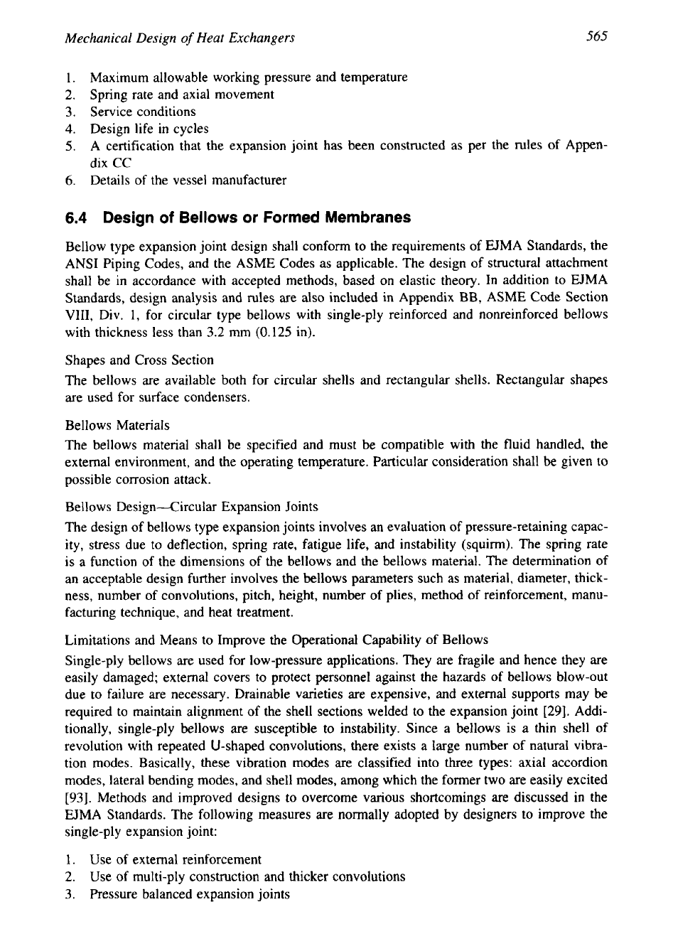
Pressure-Balanced Expansion Joints.
The pressure balanced expansion joints (Fig.
26)
are
used for applications where pressure loading upon piping or equipment is considered excessive.
The major advantage of the pressure-balanced expansion joint design is its ability to absorb
externally imposed axial movement and/or lateral deflection while restraining the pressure
thrust by means of tie devices interconnecting the flow bellows with an opposed bellows also
subjected to line pressure. Their design should be as per
EJMA
Standards.
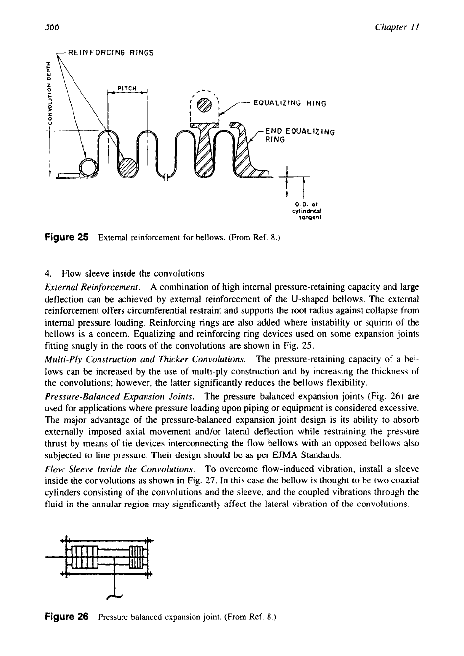
Flow
Sleeve Inside the Convolutions.
To overcome flow-induced vibration, install a sleeve
inside the convolutions as shown in Fig.
27.
In this case the bellow is thought to be two coaxial
cylinders consisting of the convolutions and the sleeve, and the coupled vibrations through the
fluid
in
the annular region may significantly affect the lateral vibration of the convolutions.
Figure
26
Pressure balanced expansion joint.
(From
Ref.
8.)
567
Mechanical Design
of
Heat Exchangers
Figure
27
Flow sleeve
to
overcome
FIV
of
bellow type expansion joint.
Fatigue Life
For a given bellows configuration and material thickness, the fatigue life
of
the bellows will
be proportional to the imposed pressure and deflection. Depending on its material of construc-
tion, the suitability of an expansion joint to withstand the required number of cycles shall be
determined from equations given in EJMA Standards or Appendix
BB
of the ASME Code.
7
OPENING AND NOZZLES
7.1
Openings
Openings in pressure vessels and heat exchangers refer to the cuts made in shells, flat covers,
channels, and heads for accommodating the nozzles and to provide manholes, peepholes, drains
and vents, instrument connections, etc. Openings can be circular, elliptical, or oblong. When-
ever an opening is made
in
the wall of the shell or in the head, the wall is weakened due to
the discontinuity in the wall and decrease in cross-sectional area perpendicular to the hoop
stress direction. To keep the local stresses within the permissible limits, reinforcements to the
openings
are
made.
Reinforcement Pad
The design of reinforcement is covered in
UG-36
to
UG-42
of the ASME Code by an area-to-
area method. Reinforced pads whenever required as per drawingdcodes shall be of the same
material or equivalent to the component to which they are welded. Even though a reinforcement
pad can be applied on either the outside or inside of the shell,
it
is the common practice to
provide it at the outside due to easiness, and no need to meet the requirement of compatibility
of the pad material with the process fluids, except that the pad should be resistant
to
general
corrosion, and of weldable equality. The factors to be kept in mind while considering the
reinforcement pad are:
1.
The pad should match the contour of the component to which it should be attached.
2.
Provide a tell-tale hole to release the entrapped gases during welding and to check the
soundness of the welding.
Reinforced Pad and Air-Soap Solution Testing
As per ASME Code UW-15, reinforcing plates and saddles of nozzles attached to the outside
vessel shall be provided with at least one tell-tale tapped hole (maximum size
NPS
1/4
tap)
for compressed air-soap solution test for tightness of welds that seal off the inside of the
vessel. Air pressure of
1.25
kg/cm2 is suggested for these tests. Higher test pressures are not
568
Chapter
1
I
recommended because the soap bubbles have a chance to blow
off.
Tell-tale holes
in
the
reinforcing pads may be left open or plugged when the vessel is in service.
7.2
Nozzles
Nozzles are incorporated to convey process fluids into the heat exchanger and out
of
it.
Their
sizes are arrived after calculating permissible fluid velocity limited by erosion-corrosion,
im-
pingement attack, pressure drop, etc. Minimum wall thickness
is
arrived using the cylindrical
shell formula. Good nozzle design involves better distribution
of
process fluids, ability
to
withstand operating load and the other loads, and should provide easy accessibility to connect
or
disconnect the pipes.
A
well designed nozzle should have a very low pressure drop. Nozzle
openings can be circular, elliptical, and oblong, Nozzles
are
connected by weldment to the
shell by
1.
Butt welding
2.
Through type
3.
Reinforcing pads
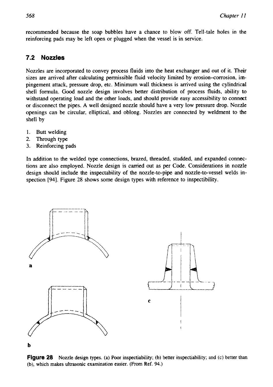
In addition to the welded type connections, brazed, threaded, studded, and expanded connec-
tions are also employed. Nozzle design is carried out as per Code. Considerations in nozzle
design should include the inspectability of the nozzle-to-pipe and nozzle-to-vessel welds in-
spection
[94].
Figure
28
shows some design types with reference to inspectibility.
I
a
C
b
Figure
28
Nozzle design types. (a) Poor inspectiability; (b) better inspectiability; and (c) better than
(b),
which makes ultrasonic examination easier. (From Ref.
94.)
Mechanical Design
of
Heat Exchangers
569
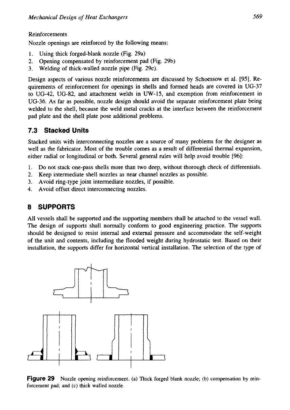
Reinforcements
Nozzle openings are reinforced by the following means:
1.
Using thick forged-blank nozzle (Fig. 29a)
2.
Opening compensated by reinforcement pad (Fig. 29b)
3.
Welding of thick-walled nozzle pipe (Fig. 29c).
Design aspects of various nozzle reinforcements are discussed by Schoessow et
al.
[95]. Re-
quirements of reinforcement for openings in shells and formed heads are covered in
UG-37
to UG-42, UG-82, and attachment welds in
UW-15,
and exemption from reinforcement in
UG-36.
As
far as possible, nozzle design should avoid the separate reinforcement plate being
welded to the shell, because the weld metal cracks at the interface between the reinforcement
pad plate and the shell plate pose additional problems.
7.3
Stacked
Units
Stacked units with interconnecting nozzles are a source of many problems for the designer as
well as the fabricator. Most of the trouble comes as
a
result of differential thermal expansion,
either radial or longitudinal or both. Several general rules will help avoid trouble [96]:
1.
Do not stack one-pass shells more than two deep, without thorough check of differentials.
2.
Keep intermediate shell nozzles as near channel nozzles as possible.
3.
Avoid ring-type joint intermediate nozzles, if possible.
4.
Avoid offset direct interconnecting nozzles.
8
SUPPORTS
All vessels shall be supported and the supporting members shall be attached to the vessel wall.
The design
of
supports shall normally conform to good engineering practice. The supports
should be designed to resist internal and external pressure and accommodate the self-weight
of the unit and contents, including the flooded weight during hydrostatic test. Based on their
installation, the supports differ for horizontal vertical installation. The selection of the type of
Figure
29
Nozzle opening reinforcement. (a) Thick forged blank nozzle;
(b)
compensation by rein-
forcement pad; and (c) thlck walled nozzle.
570
Chapter
I1
support for a pressure vessel is dependent on parameters such as the elevation of the vessel
from the ground level, the materials of construction, and the operating temperature
[44].
8.1
Design
Loads
While designing the supports of a vessel, care should be taken to include all the external loads
likely to be imposed
on
it. Such external loads include:
(1)
wind loads,
(2)
loads due
to
connected piping,
(3)
superimposed loads,
(4)
shock loads due to surging or hydraulic hammer,
and
(5)
seismic vibration.
As
per
TEMA
Standards, supports for a removable tube bundle heat
exchanger should be designed
to
withstand a pulling force equal to
1.5
times the weight of the
tube bundle, and when additional loads and forces from external nozzle loadings, wind loads,
and seismic forces are assumed for the purposes of supports design, the combinations need not
be assumed to occur simultaneously. Care should be taken that the thermal stresses
in
external
supports do not exceed those permitted by the code.
8.2
Horizontal
Vessel Supports
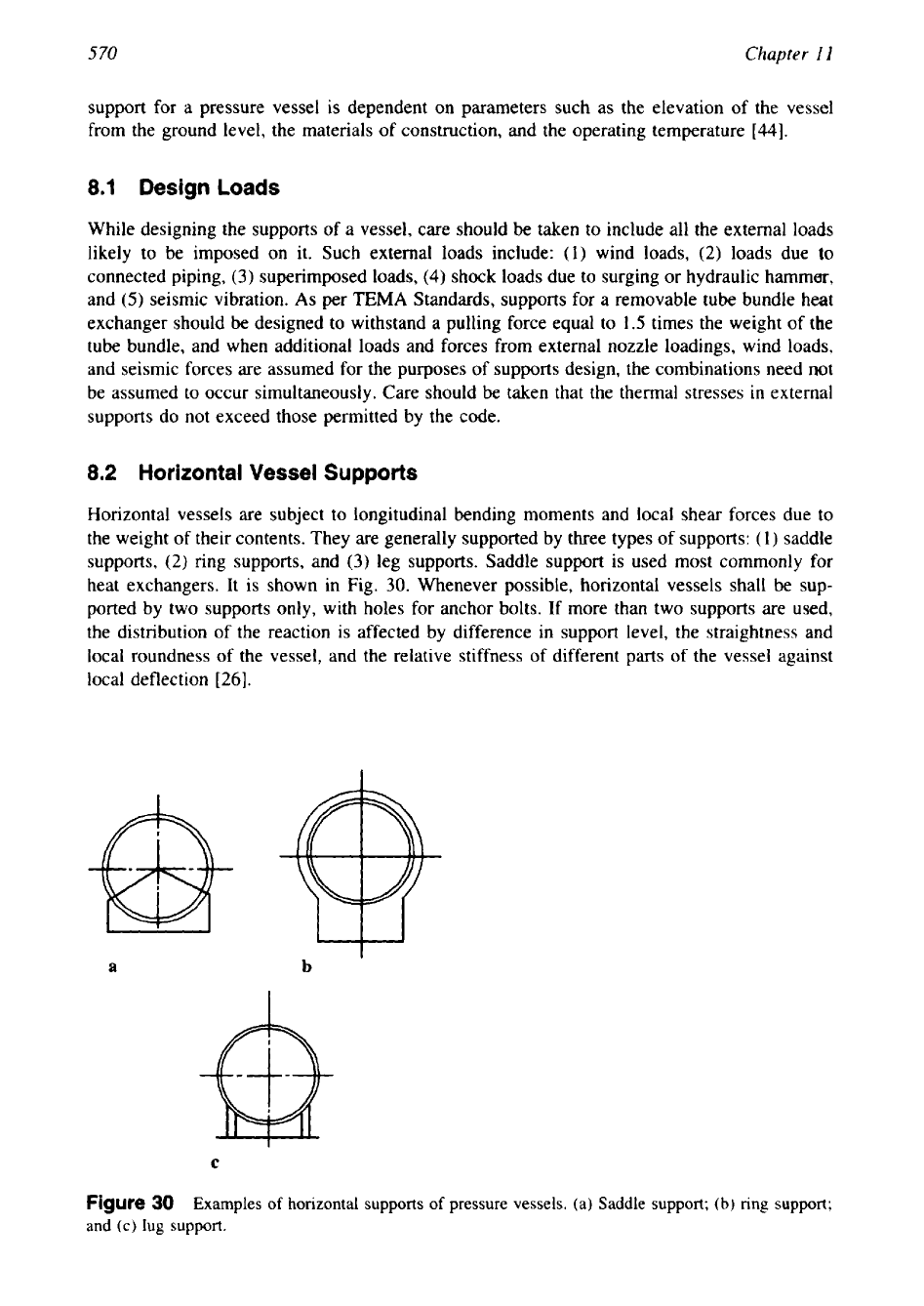
Horizontal vessels are subject to longitudinal bending moments and local shear forces due to
the weight of their contents. They are generally supported by three types of supports:
(1)
saddle
supports,
(2)
ring supports, and
(3)
leg supports. Saddle support is used most commonly for
heat exchangers. It is shown in Fig.
30.
Whenever possible, horizontal vessels shall be sup-
ported by two supports only, with holes for anchor bolts.
If
more than two supports are used,
the distribution of the reaction is affected by difference in support level, the straightness and
local roundness of the vessel, and the relative stiffness of different parts of the vessel against
local deflection
[26].
a
b
6-
C
Figure
30
Examples
of
horizontal supports
of
pressure vessels. (a) Saddle support;
(b)
ring
support;
and
(c)
lug
support.
Mechanical Design
of
Heat Exchangers
5
71
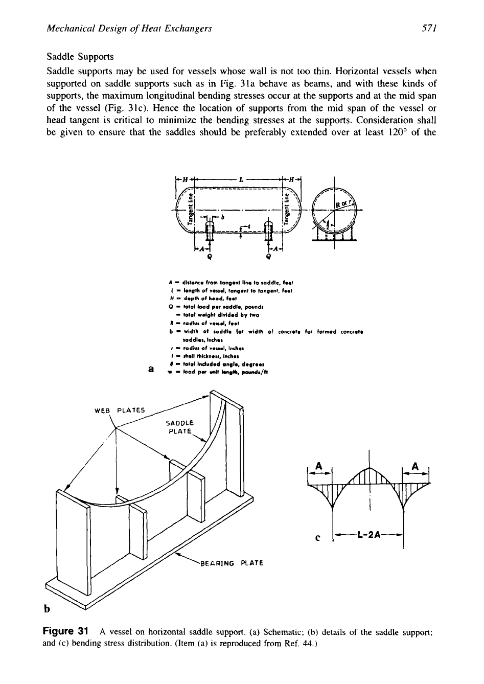
Saddle Supports
Saddle supports may be used for vessels whose wall is not too thin. Horizontal vessels when
supported on saddle supports such as in Fig. 31a behave as beams, and with these kinds
of
supports, the maximum longitudinal bending stresses occur at the supports and at the mid span
of
the vessel (Fig. 31c). Hence the location
of
supports from the mid span
of
the vessel or
head tangent is critical to minimize the bending stresses at the supports. Consideration shall
be given to ensure that the saddles should be preferably extended over at least
120"
of the
LA4
LA4
0
Q
A
=
dlrtonco
from
tongont lino to soddle, foot
1
-
Iongth
of
votrol,
tongont
fo
tongent, 1.01
H
=
doplh
of
hood,
fool
0
=
total lood por soddlo, pounds
R
-
=
totol woighl dividod
by
two
rodiur
of
vouel,
fool
b
=
wldth
of
raddlo
(or
width
of
concreto for formod concroto
raddlos, inches
=
rodwr
of
voirol.
=.
lnchor
r
rholl
thidcnorr, lmchor
8
-
total Indudod onglo, dogroor
I
a
w
-
bod
PU
unll
Iongth,
poundr/ft
Figure
31
A
vessel on horizontal saddle support.
(a)
Schematic; (b) details of the saddle support;
and (c) bending stress distribution. (Item
(a)
is reproduced from Ref.
44.)
572
Chapter
11
circumference of the vessel. The limitation, which is imposed by most codes of practice is an
empirical one based on experience with large vessels
[26].
Zick
Stress.
Zick
[97]
developed a method for analyzing supports for the horizontal cylindri-
cal shells. The analysis gives a detailed derivation of the equations for longitudinal bending
stresses at the supports and at the mid span. These stresses are named as Zick stress. Zick’s
method is discussed in detail in refs. 41, 42, and
45,
among others. Zick’s method is adopted
in codes such as IS:2825-1969 and
BS
5500.
Ring Supports
Ring supports as shown in Fig. 30b are preferred to saddle supports for large thin-walled
vessels, vacuum vessels, and in the case
of
saddles located away from the head. Ring supports
are also preferred when to support a vessel at more than two cross sections becomes inevitable.
The welds attaching ring supports should have a minimum leg length equal to the thickness
of
the thinner of the two parts being joined together.
Leg Supports
Leg supports as shown in Fig. 30c are usually permitted for small vessels by the usual code
practice because of the severe local stresses that can be set up at the connection of the support
to the vessel wall.
8.3
Vertical
Vessels
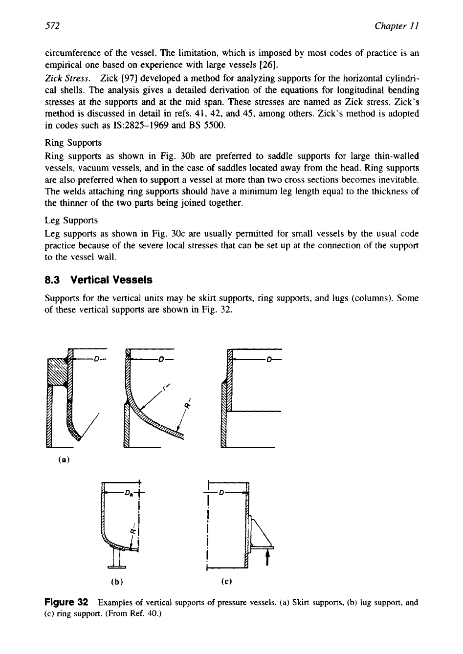
Supports for the vertical units may be skirt supports, ring supports, and lugs (columns). Some
of these vertical supports are shown in Fig. 32.
Figure
32
Examples
of
vertical supports of pressure vessels. (a) Skirt supports,
(b)
lug support, and
(c)
ring
support. (From Ref.
40.)
Mechanical Design
of
Heat Exchangers
573
Skirt Supports
Skirt supports (Fig. 32a) are recommended for largehall vertical vessels. Skirt supports are
preferred because they do not lead to concentrated local loads on the shell, offer less restraint
against differential thermal expansion, and reduce the effect of discontinuity stresses at the
junction of the cylindrical shell and the bottom
[26].
The skirt supports shall be provided with
at least one opening for inspection unless there
is
a provision to examine the bottom of the
vessel accessible from below.
Lug supports
Vertical vessels may be supported by a number of posts or lugs as shown in Fig. 32b. Lug
supports are ideal for thick-walled vessels. For thin-walled vessels, it is not convenient unless
proper reinforcements are used or many lugs are welded. Brackets or lugs offer many advan-
tages over other types
of
vessels [41]: They are inexpensive, can absorb diametrical expansion
by sliding over greased or bronze plates, and requirements of welding are minimal.
8.4 Procedure for Support Design
TEMA Rules for Supports Design (G-7.1)
TEMA rules for supports for horizontal units are listed in G-7.11 and for vertical units
in
G-7.12. For calculating resulting stresses due to the saddle supports, references are suggested
under TEMA G-7.13. The “Recommended Good Practice” section of TEMA Standards pro-
vides additional information on support design.
ASME Code
ASME Code requirements for supports design are covered in UG-54. Appendix G contains
suggested good practices for support design.
8.5
Lifting Devices and Attachments
TEMA rules for the design of lifting devices are given in G-7.2. ASME Code rules for the
construction of lifting devices and fitting attachments are covered in
UG-82.
Some of the
TEMA Standards for design of lifting devices are as follows:
1. Channels, bonnets, and covers that weigh more than
60
pounds are to be provided with
lifting lugs.
2.
Lifting devices are designed to lift the component to which they are directly attached.
When lifting lugs are required by the purchaser to lift the complete unit, the device must
be adequately designed.
3.
The design load shall incorporate an appropriate impact factor.
4.
Lifting devices and attachments shall be formed and fitted to conform to the curvature of
the component surface to which they are attached.
REFERENCES
la. Hirschfeld, F., Codes, standards and certificate of authorization program: Part 1-Establishing
safety standards,
Mech.
Eng.,
January, 33-39 (1979).
1
b.
Hirschfeld, F., Codes, standards and certificate of authorization program: Part 2-Policies, programs
and organization,
Mech.
Eng.,
February, 31-37 (1979).
2.
Statement of the Council on Codes and Standards of the American Society of Mechanical Engineers
on the federal role in international standards,
Tram.
ASME,
J.
Pressure Vessel
Techrrol.,
II2,
425-
426
(1990).