Kuppan T. Heat Exchanger Design Handbook
Подождите немного. Документ загружается.

534
Chapter
I
I
the two tube sheets. This differential radial expansion of the adjacent tube sheets may be caused
by the two tube sheets having different coefficients of thermal expansion and/or differences
in
mean metal temperatures. The portion of tube bundle between the two tube sheets induces
coupling between out-of-plane bending and direct radial expansion of the two tube sheets.
Therefore,
in
contrast to the single tube-sheet analyses, any double tube-sheet analysis must
encompass both tube-sheet bending and radial growth. These requirements make the solution
procedure amenable to computer analysis only. Design of double tube sheets is discussed by
Singh and Soler
[41].
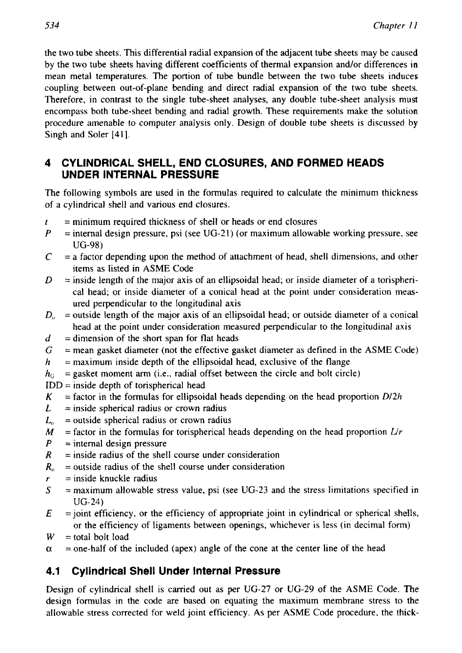
4
CYLINDRICAL SHELL, END CLOSURES, AND FORMED HEADS
UNDER INTERNAL PRESSURE
The following symbols are used in the formulas required to calculate the minimum thickness
of
a cylindrical shell and various end closures.
t
=
minimum required thickness of shell or heads or end closures
P
=
internal design pressure, psi (see
UG-21)
(or maximum allowable working pressure, see
UG-98)
C
=
a factor depending upon the method of attachment of head, shell dimensions, and other
items as listed in
ASME
Code
D
=
inside length of the major axis of an ellipsoidal head; or inside diameter of
a
torispheri-
cal head; or inside diameter of a conical head at the point under consideration meas-
ured perpendicular to the longitudinal axis
D,,
=
outside length of the major axis of an ellipsoidal head; or outside diameter of a conical
head at the point under consideration measured perpendicular to the longitudinal axis
d
=
dimension of the short span for flat heads
C
=
mean gasket diameter (not the effective gasket diameter as defined in the
ASME
Code)
h
=
maximum inside depth of the ellipsoidal head, exclusive of the flange
hG
=
gasket moment
arm
(i.e., radial offset between the circle and bolt circle)
IDD
=
inside depth of torispherical head
K
=
factor in the formulas for ellipsoidal heads depending on the head proportion
D/2h
L
=
inside spherical radius or crown radius
L,
=
outside spherical radius or crown radius
M
=
factor in the formulas for torispherical heads depending on the head proportion
Llr
P
=
internal design pressure
R
=
inside radius of the shell course under consideration
R,,
=
outside radius of the shell course under consideration
r
=
inside knuckle radius
S
=
maximum allowable stress value, psi (see
UG-23
and the stress limitations specified
in
UG-24)
E
=joint efficiency, or the efficiency of appropriate joint in cylindrical or spherical shells,
or the efficiency of ligaments between openings, whichever is less (in decimal form)
W
=total bolt load
a
=
one-half of the included (apex) angle of the cone at the center line of the head
4.1
Cylindrical Shell Under Internal Pressure
Design of cylindrical shell is carried out as per
UG-27
or
UG-29
of the
ASME
Code. The
design formulas in the code are based on equating the maximum membrane stress to the
allowable stress corrected for weld joint efficiency.
As
per
ASME
Code procedure, the thick-
Mechanical Design
of
Heat Exchangers
535
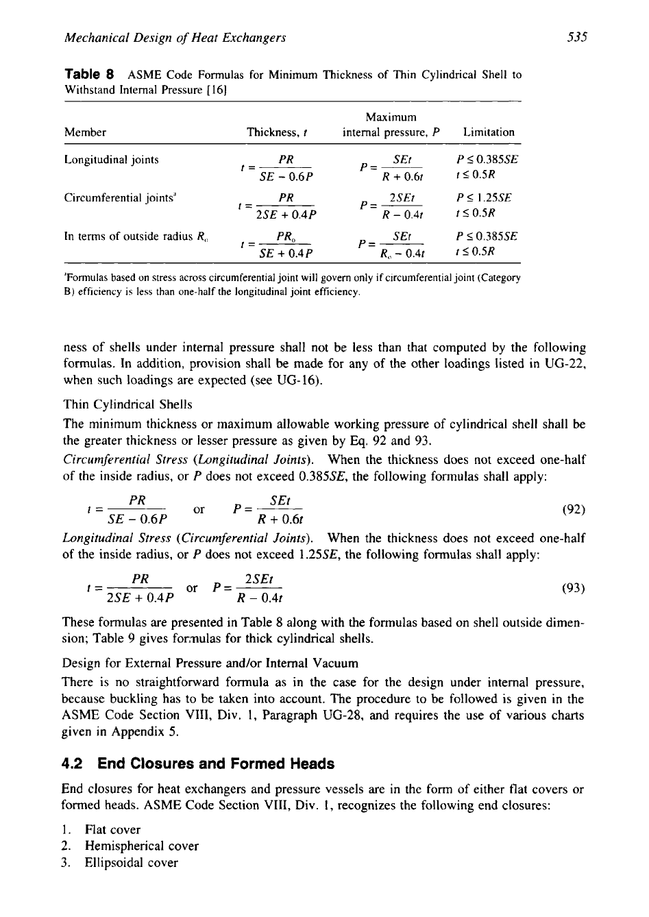
Table
8
ASME
Code Formulas for Minimum Thickness
of
Thin Cylindrical Shell to
Withstand Internal Pressure
[
161
Maximum
Member
Thickness,
t
internal pressure,
P
Limitation
Longitudinal joints
PR
t=
SE
-
0.6P
Circumferential jointsa
PR
p=-
2SEt P
I
1.25SE
t=
2SE
+
0.4P
R
-
0.4t
t
IOSR
In terms of outside radius
R,
t=
PRO
SEt
P
I0.385SE
SE
+
0.4P
p=-
R,
-
0.4t
t
I0.5R
'Formulas based on stress across circumferential joint will govern only if circumferential joint (Category
B)
efficiency is less than one-half
the
longitudinal joint efficiency.
ness of shells under internal pressure shall not be less than that computed by the following
formulas. In addition, provision shall be made for any of the other loadings listed in
UG-22,
when such loadings are expected (see
UG-16).
Thin Cylindrical Shells
The minimum thickness or maximum allowable working pressure of cylindrical shell shall be
the greater thickness or lesser pressure as given by Eq.
92
and
93.
Circumferential Stress (Longitudinal Joints).
When the thickness does not exceed one-half
of the inside radius, or
P
does not exceed
0.385SE,
the following formulas shall apply:
PR
SEt
t=
or
P=-
SE
-
0.6P
R
+
0.6t
Longitudinal Stress (Circumferential Joints).
When the thickness does not exceed one-half
of the inside radius, or
P
does not exceed
1.25SE,
the following formulas shall apply:
PR
2SEt
t=
or
P=-
(93)
2SE
+
0.4P
R
-
0.4t
These formulas are presented in Table
8
along with the formulas based on shell outside dimen-
sion; Table
9
gives formulas for thick cylindrical shells.
Design for External Pressure and/or Internal Vacuum
There is no straightforward formula as in the case for the design under internal pressure,
because buckling has to be taken into account. The procedure to be followed is given in the
ASME
Code Section VIII, Div.
1,
Paragraph
UG-28,
and requires the use of various charts
given in Appendix
5.
4.2 End Closures and Formed Heads
End closures for heat exchangers and pressure vessels are
in
the form of either flat covers
or
formed heads.
ASME
Code Section VIII, Div.
1,
recognizes the following end closures:
1.
Flat cover
2.
Hemispherical cover
3.
Ellipsoidal cover
536
Chapter
11
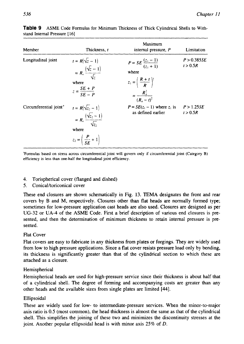
Table
9
ASME
Code Formulas for Minimum Thickness of Thick Cylindrical Shells to With-
stand Internal Pressure
[
161
~
~~
Maximum
Member
Thickness,
t
internal pressure,
P
Limitation
Longitudinal joint
t=
R(&-
1)
P
>
0.385SE
t
>
0.5R
(6-
=
R,
1)
where
7)
4:
Zl=(
R+t:
where
SE
+
P
z=-------
SE
-
P
-
--
R:
(R,
-
t)2
Circumferential jointd
t
=
R(&
-
1)
P
=
SE(zl
-
1)
where
zI
is
P
>
1.25SE
as
defined earlier
t
>
0.5R
(6-
1)
=
R,
-
&
where
'Formulas based on stress across circumferential joint
will
govern only if circumferential joint (Category
B)
efficiency is less than one-half the longitudinal joint efficiency.
4.
Torispherical cover (flanged and dished)
5.
Conical/toriconical cover
These end closures are shown schematically in Fig.
13.
TEMA designates the front and rear
covers by
B
and M, respectively. Closures other than flat heads are normally formed type;
sometimes for low-pressure application cast heads are also used. Closures are designed as per
UG-32
or
UA-4
of the
ASME
Code. First a brief description
of
various end closures is pre-
sented, and then the determination of minimum thickness to retain internal pressure
is
p~-
sented.
Flat Cover
Flat covers are easy to fabricate in any thickness from plates
or
forgings. They are widely used
from low to high pressure applications, Since a flat cover resists pressure load only by bending,
its thickness is significantly greater than that of the cylindrical section to which these are
attached as a closure.
Hemispherical
Hemispherical heads are used for high-pressure service since their thickness is about half that
of a cylindrical shell. The degree of forming and accompanying costs are greater than any
other heads and the available sizes from single plates are limited
[a].
Ellipsoidal
These are widely used for low- to intermediate-pressure services. When the minor-to-major
axis ratio is
0.5
(most common), the head thickness is almost the same as that of the cylindrical
shell. This simplifies the joining of these two and minimizes the discontinuity stresses at the
joint. Another popular ellipsoidal head is with minor axis 25% of
D.
537
Mechanical Design
of
Heat Exchangers
\\I
//
r'
\\I/
Y
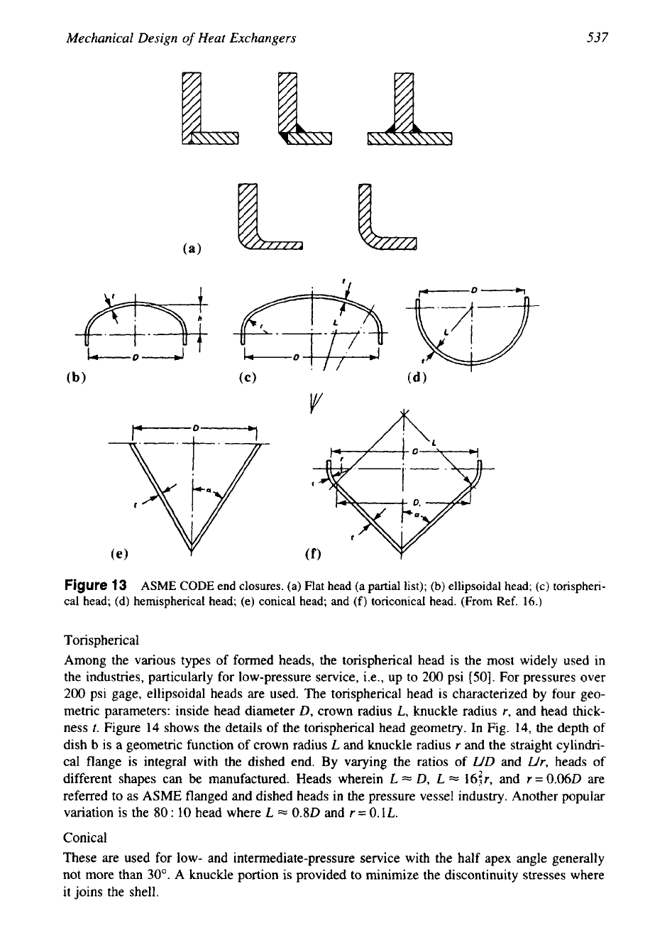
Figure
13
ASME
CODE end closures. (a) Flat head (a partial list);
(b)
ellipsoidal head; (c) torispheri-
cal head; (d) hemispherical head; (e) conical head; and
(f)
toriconical head.
(From
Ref.
16.)
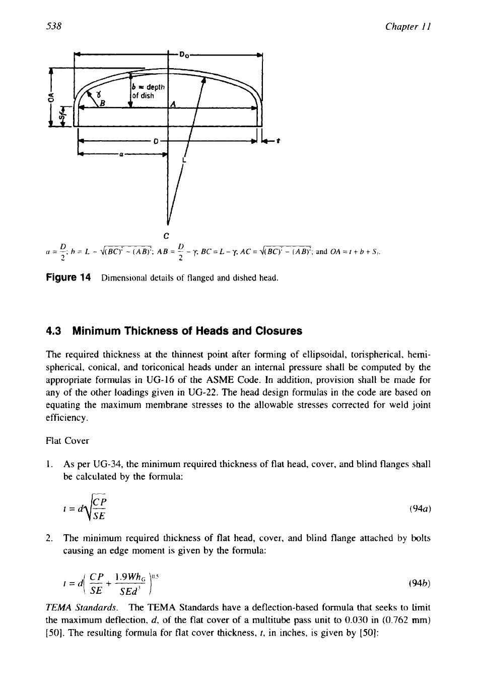
Torispherical
Among the various types of formed heads, the torispherical head is the most widely used in
the industries, particularly for low-pressure service, i.e., up to
200
psi
[50].
For pressures over
200
psi gage, ellipsoidal heads are used. The torispherical head is characterized by four geo-
metric parameters: inside head diameter
D,
crown radius
L,
knuckle radius
r,
and head thick-
ness
t.
Figure
14
shows the details
of
the torispherical head geometry. In Fig.
14,
the depth
of
dish b is a geometric function of crown radius
L
and knuckle radius
r
and the straight cylindri-
cal flange is integral with the dished end. By varying the ratios of
WD
and
Wr,
heads of
different shapes can be manufactured. Heads wherein
L
=
0,
L
=
16$r,
and
r
=
0.060
are
referred to as
ASME
flanged and dished heads in the pressure vessel industry. Another popular
variation
is
the
80
:
10
head where
L
=
0.80
and
t
=
0.1L.
Conical
These are used for low- and intermediate-pressure service with the half apex angle generally
not more than
30".
A
knuckle portion is provided to minimize the discontinuity stresses where
it joins the shell.
538
Chapter
I
I
b
=
depth
U
of
dish
A
C
D
D
CI
=
-;
b
=
L
-
d(BC)'
-
(AB)';
AB
=
-
-
y
BC
=
L
-
y;
AC
=
d(BC)'
-
(AB)';
and
OA
=
t
+
b
+
S,.
2
2
Figure
14
Dimensional details
of
flanged and dished head.
4.3
Minimum Thickness
of
Heads and
Closures
The required thickness at the thinnest point after forming of ellipsoidal, torispherical, hemi-
spherical, conical, and toriconical heads under an internal pressure shall be computed by the
appropriate formulas in
UG-16
of the
ASME
Code.
In
addition, provision shall be made
for
any
of
the other loadings given
in
UG-22.
The head design formulas in the code are based on
equating the maximum membrane stresses to the allowable stresses corrected for weld joint
efficiency.
Flat Cover
1.
As
per
UG-34,
the minimum required thickness of flat head, cover, and blind flanges shall
be calculated by the formula:
t=d
-
(944
I/'
2.
The minimum required thickness
of
flat head, cover, and blind flange attached by bolts
causing an edge moment is given by the formula:
TEMA
Standards.
The TEMA Standards have a deflection-based formula that seeks to limit
the maximum deflection,
d,
of the flat cover of a multitube pass unit to
0.030
in
(0.762
mm)
[50].
The resulting formula for flat cover thickness,
t,
in inches,
is
given by
[SO]:
539
Mechanical Design
of
Heat Exchangers
1.425G4P+
0.5hGA,G
x
106
1'3
(95)
t=[
E
Ed
f2
1
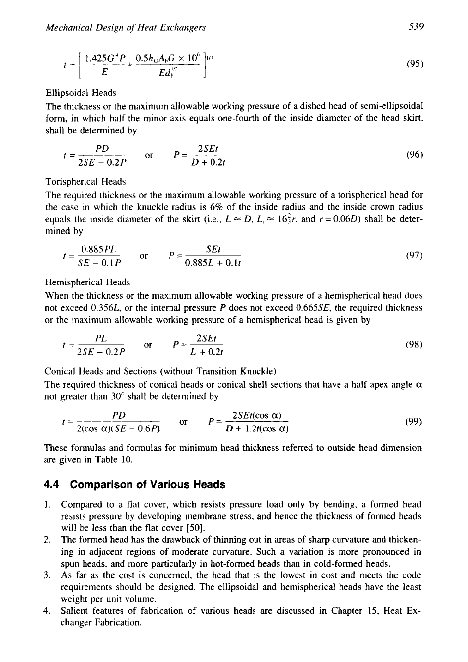
Ellipsoidal Heads
The thickness or the maximum allowable working pressure of a dished head of semi-ellipsoidal
form, in which half the minor axis equals one-fourth of the inside diameter of the head skirt,
shall be determined by
PD
2SEt
t=
or
P=-------
2SE
-
0.2P
D
+
0.2t
Torispherical Heads
The required thickness or the maximum allowable working pressure
of
a torispherical head for
the case in which the knuckle radius is
6%
of the inside radius and the inside crown radius
equals the inside diameter of the skirt (i.e.,
L
=
D,
Li
=
16:r,
and
r=
0.06D)
shall be deter-
mined by
0.885
PL
t=
SE
-
0.1
P
or
SEt
0.885L
+
O.lt
P=
(97)
Hemispherical Heads
When the thickness or the maximum allowable working pressure of
a
hemispherical head does
not exceed
0.356L,
or the internal pressure
P
does not exceed
0.665SE,
the required thickness
or the maximum allowable working pressure of a hemispherical head is given by
PL
2SEt
t=
or
P=-------
2SE
-
0.2P
L
+
0.21
Conical Heads and Sections (without Transition Knuckle)
The required thickness of conical heads or conical shell sections that have a half apex angle
a
not greater than
30"
shall be determined by
PD
2SEt(cos
a)
t=
or
P=
C COS
a)(SE
-
0.6P)
D
+
1.2t(cos
a)
(99)
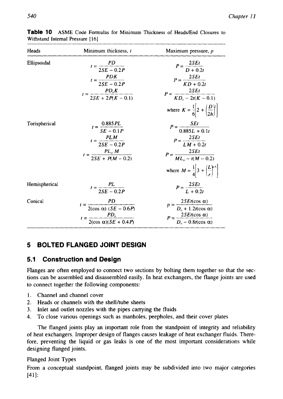
These formulas and formulas for minimum head thickness referred to outside head dimension
are given in Table
10.
4.4
Comparison
of
Various
Heads
1.
Compared to a flat cover, which resists pressure load only by bending, a formed head
resists pressure by developing membrane stress, and hence the thickness of formed heads
will be less than the flat cover
[50].
2.
The formed head has the drawback of thinning out in areas of sharp curvature and thicken-
ing in adjacent regions
of
moderate curvature. Such a variation is more pronounced in
spun heads, and more particularly in hot-formed heads than in cold-formed heads.
3.
As
far as the cost
is
concerned, the head that
is
the lowest in cost and meets the code
requirements should be designed. The ellipsoidal and hemispherical heads have the least
weight per unit volume.
4.
Salient features of fabrication of various heads are discussed in Chapter
15,
Heat
Ex-
changer Fabrication.
540
Chapter
I1
Table
10
ASME Code Formulas for Minimum Thickness of Heads/End Closures
to
Withstand Internal Pressure
[
161
Heads Minimum thickness,
t
Maximum pressure,
p
Ellipsoidal
PD
p=-
2SEt
t=
2SE
-
0.2P
D
+
0.2t
PDK
2SEt
t=
P=
2SE
-
0.2P
KD
+
0.2t
PD,K
2SEt
t=
P=
2SE
+
2P(K
-
0.1)
KD,,
-
2t(K
-
0.1)
Torispherical
0.885
PL
SEt
t=
P=
SE
-
0.1
P
0.8851,
+
O.lt
PL
M
2SEt
t=
P=
2SE
-
0.2P
LM
+
0.2t
PLO
M
P=
2SEt
t=
2SE
+
P(M
-
0.2)
ML,,
-
t(M
-
0.2)
where
M
=
a[
3
+
(37
Hemispherical
PL
p=
___
2SEt
t=
2SE
-
0.2P L
+
0.2t
Conic a1
PD
2SEt(cos
a)
t=
C COS
a)
(SE
-
0.6P)
=
D,
+
1.2t(cos
a)
PD,
P=
2SEt(cos
a)
t=
COS
a)(SE
+
0.4P)
Do
-
0.8t(cos
a)
5
BOLTED FLANGED JOINT DESIGN
5.1
Construction and Design
Flanges are often employed to connect two sections by bolting them together
so
that the sec-
tions can be assembled and disassembled easily. In heat exchangers, the flange joints are used
to connect together the following components:
1.
Channel and channel cover
2.
Heads or channels with the shellkube sheets
3.
Inlet and outlet nozzles with the pipes carrying the fluids
4.
To
close various openings such as manholes, peepholes, and their cover plates
The flanged joints play an important role from the standpoint
of
integrity and reliability
of heat exchangers. Improper design of flanges causes leakage of heat exchanger fluids. There-
fore, preventing the liquid or gas leaks is one
of
the most important considerations while
designing flanged joints.
Flanged Joint Types
From a conceptual standpoint, flanged joints may be subdivided into two major categories
[41]:
541
Mechanical Design
of
Heat Exchangers
1.
Bolted joints
2.
Pressure-actuated or self-energizing joints
The bolted joint is by far the most common type. The basic difference between these two
joint types lies in the manner by which the pressure load is resisted and leak tightness is
achieved.
A
bolted joint essentially consists of a gasket interposed between two structural
members called flanges, which in
turn
are connected to other structural members like cylindri-
cal shells or pipes, and a set of bolts for joining together the two flanges. To make the joint,
the gasket is compressed to a desired value by prestressing the bolts. Pressure-actuated joints
exploit the header pressure force to compress and
to
seal the gasket. Pressure-actuated joints
find application in the higher pressure range, typically over
2000
psi [41].
Constructional Details of Bolted Flange Joints
Types
of
Bolted Flanges.
Based on the width of gasket, flange joints are classified as (1) ring
type gasket joint and
(2)
full-face gasket joint. For very-low-pressure applications
(100-3OO
psi), wide gaskets that span the entire flange face may be used. This construction is known as
“full-face gasket” design.
A
design method for flanges utilizing full-face gaskets is presented
in ref 4 1. In general, for high-pressure and medium- to high-pressure applications, only ring
type gaskets are used. Sometimes even for low-pressure applications ring type gaskets are
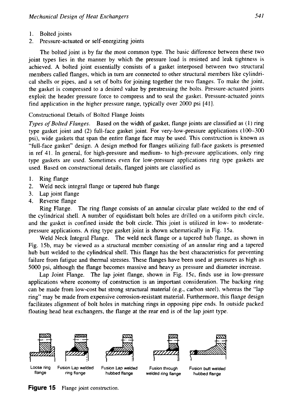
used. Based on constructional details, flanged joints are classified as
1. Ring flange
2.
Weld neck integral flange or tapered hub flange
3.
Lap joint flange
4.
Reverse flange
Ring Flange. The ring flange consists
of
an annular circular plate welded to the end of
the cylindrical shell.
A
number
of
equidistant bolt holes are drilled on a uniform pitch circle,
and the gasket is confined inside the bolt circle. This joint is utilized in low- to moderate-
pressure applications.
A
ring type gasket joint is shown schematically in Fig. 15a.
Weld Neck Integral Flange.
The weld neck flange or a tapered hub flange, as shown in
Fig. 15b, may be viewed as a structural member consisting of an annular ring and a tapered
hub butt welded to the cylindrical shell. This flange has the best characteristics for preventing
failure from fatigue and thermal stresses. These flanges have been used at pressures as high as
5000
psi, although the flange becomes massive and heavy as pressure and diameter increase.
Lap Joint Flange.
The lap joint flange, shown in Fig. 15c, finds use in low-pressure
applications where economy of construction is an important consideration. The backing ring
can be made from low-cost but strong structural material (e.g., carbon steel), whereas the “lap
ring” may be made from expensive corrosion-resistant material. Furthermore, this flange design
facilitates alignment of bolt holes in matching rings in opposing pipe ends. In outside packed
floating head heat exchangers, the flange at the rear end is of the lap joint type.
Loose
ring
flange
Fusion
Lap
welded
ring flange
Fusion Lap welded
hubbed flange
Fusion through
welded ring flange
Fusion butt welded
hubbed flange
Figure
15
Flange
joint
construction.
542
Chapter
11
Design of Bolted Flange Joints
The objectives in flange design are to ensure that the residual gasket stress levels and the
pressure induced in the flange during bolt preload, as well as under operating conditions. do
not exceed allowable stress values in the structural members.
The earliest treatment of the problem
of
flange design to receive widespread recognition
was that of Waters et al.
[82],
which gave the general basis for the design rules in the ASME
Code. Design of flanged joints with ring type gaskets is carried out as per Appendix
2
of
ASME Code Section
VIII,
Div.
1.
Appendix
S
of
the Code gives general guidelines for bolting
requirements of flanges. The Code method for design
of
integral type flange and ring flange
is briefly described here. Unless otherwise mentioned, the mention of
ASME
Code throughout
this book refers
to
ASME Code Section
VIII,
Div.
1
(1992 edition) only
[
161.
ASME
Code Classification
of
Circular Flanges for Design Purposes.
For computation pur-
poses, ASME Code Section
VIII,
Div.
l,
classifies circular flanges with ring type gaskets
as
1.
Loose type flanges
2.
Integral type flanges
3.
Optional type flanges
4.
Flanges with
nut
stop
5.
Reverse flanges
Salient constructional details, design features, and step-by-step design procedures
of
vari-
ous flanged joint types except flanges with
nut
stop and reverse flanges are described in the
following sections.
Loose Type Flanges. This type covers those designs
in
which the flange has no direct
connection to the nozzle neck, vessel, or pipe wall, and designs where the method of attach-
ment is not considered to give the mechanical strength equivalent of integral attachment. Fig-
ures
1
to 4a of the ASME Code conform to loose type flanges
[
161.
Integral Type Flanges.
This type covers those designs in which the flange is cast or
forged integrally with the nozzle neck, vessel,
or
pipe wall, butt welded thereto, or attached
by other forms of arc or gas welding of such a nature that the flange and nozzle neck and
vessel or pipe wall are considered to be the equivalent of an integral structure. Figures
5
to
7
of the ASME Code
[
161 conform to integral type flanges.
Optional Type Flanges. This type covers those designs
in
which the attachment of the
flange to the nozzle neck, vessel, or pipe wall is considered to act as a unit, which shall be
calculated as an integral flange, except that for simplicity the designer may calculate the con-
struction as a loose type flange provided none of the values given in the ASME Code are
exceeded. Figures
12
and 12a of the ASME Code [16] conform
to
optional type flanges.
Design Procedure.
The integrity and reliability of a bolted flanged joint depend to a large
extent upon the correct choice of materials, dimensions, and loads on the gasket. The flange
design procedure can be summarized as three separate elements:
1.
Gasket design
2.
Bolting design
3.
Flange design
To start with, materials of construction
of
flange, bolting and gasket, and gasket properties are
chosen. Flange inner diameter and shell thickness to which the flange is to be welded are also
known. A rough guess of the various dimensions of the flange is made, taking into account
the permissible hub slope, and minimum hub length in the case of weld neck flange, and
bolting dimensional requirements. Suitable gasket outer diameter and width are also chosen,
543
Mechanical Design
of
Heat Exchangers
keeping the minimum width requirements, Flange dimensions shall be such that the calculated
stresses in the flange shall not exceed code stress values. In the following paragraphs, the
detailed design procedures of the three elements of flange design are described.
Gasket Design
.
Gaskets and Their Characteristics.
A
leak-proof joint with metal-to-metal surfaces with-
out a gasket is difficult to achieve even with use of accurately machined fine finish surfaces.
Surface irregularities only a few millionths of
an
inch will permit the escape of a fluid under
pressure
[44].
Being a semiplastic material, the gasket deforms under load, which in turn seals
the minute surface irregularities and prevents leakage of the fluid.
Selection of Gasket Material.
A gasket is essentially an elastoplastic material that is
softer than the flange faces. In the gasket seating condition the entire bolt load is borne by the
gasket. Hence, the gasket must be strong enough to withstand load due to bolting and operating
conditions without crushing or extruding out. Therefore, soft materials like asbestos and or-
ganic fibers are precluded for high-pressure applications.
Also,
the gasket material shall with-
stand the operating temperature and exhibit corrosion resistance to the fluid contained in the
pressure vessel [83].
Gasket Materials.
Gaskets are made out of a myriad variety
of
materials. Good references
are available from many gasket manufacturers for the selection of proper gaskets for the in-
tended applications. Table
2-5.1
of the ASME Code gives a list of many commonly used
gasket materials (see Table
11).
This is a partial list of gasket materials included in Table
2-
5.1
of the ASME Code
[
161:
Elastomers without fabric or high percentage of asbestos fiber
Asbestos with suitable binder
Elastomers with cotton fabric insertion
Elastomers with asbestos fabric insertion
Spiral-wound asbestos-filled metal
Corrugated metal with asbestos fill
Corrugated metal
Flat metal, jacketed asbestos fill
Grooved metal
Solid flat metal
The choice of the gasket material is often based upon the required gasket width. If the gasket
is made too narrow, the unit pressure on it may be excessive, whereas if the gasket is made
too wide, the bolt load will be unnecessarily high
[44].
Gasket Factors. The basic behavior of the gasket is defined by the gasket factor
rn
and
gasket
or
joint contact surface unit seating load
y,
which are tabulated in the ASME Code,
Section VIII, Div.
1.
Gasket Factor,
in.
This is the ratio of the residual stress on the gasket under operating
pressure to that pressure. In other words,
rn
=
(bolt load
-
hydrostatic end load)/(gasket area
x
internal pressure).
Gasket or Joint Contact Surface Unit Seating Load,
y.
This is the stress required to make
the gasket surface take up the shape of the flange faces, or the gasket stress required to contain
zero internal pressure. The factor
y
is usually expressed as a unit stress in pounds per square
inch and is independent of the pressure in the vessel. Table
2-5.1
of the ASME Code gives
suggested design values of gasket factor
rn
and minimum design seating stress
y.