Kuppan T. Heat Exchanger Design Handbook
Подождите немного. Документ загружается.

524
Chapter
I1
=
p:
-
p:
+
pd
where
p:, pi,
and
Pd
are the same as in
Eq.
42, 44,
and
40,
respectively.
Stress Category Concept
in
CODAP
Formula.
The stress category concept used in CODAP
is discussed by Osweiller [70]. The primary membrane stress plus bending stress in the tube
sheet is limited to
1.5f
(f=
nominal or allowable design stress in CODAP). When the tube
sheet
is
not extended as a flange, the bending stress due
to
pressures has been taken up to
2fi
When the tube-sheet rim is extended as a flange, the additional moment at the periphery of the
tube sheet is taken into account by limiting the allowable stress to 1Sf.
Fixed Tube-Sheet Formula as per BS
5500
The fixed tube-sheet design formula of BS
5500
[18] bears certain commonalities with the
fixed tube-sheet design procedure of CODAP and TEMA. Similar to CODAP, the fixed tube-
sheet formula in BS
5500
takes into account the tube-sheet restraint offered by shell and
channel
to
the tube sheet through the term
H,(X,Z).
However, the effective design pressure is
calculated like the TEMA procedure. The minimum tube-sheet thickness shall be greater of
the values calculated to resist bending and shear given by the following formulas.
Bending:
Shear:
Simultaneous action of both the shell-side and tube-side pressure: If agreed, the design
shall be based on the simultaneous action
of
both the shell-side and tube-side pressure (TEMA
specifies this condition as effective differential pressure design; RCB-7.165)
Bending:
Shear:
where
Gl
is the diameter to which shell-side pressure is acting,
G2
the diameter to which tube-
side pressure is acting,
Dot,
the diameter of the outer tube limit circle,
s,,
the allowable
stress
in BS
5500,
pI
the shell-side effective design pressure,
p2
the tube-side effective design pres-
sure,
Pd
the effective differential design pressure,
a
the design stress factor (its value is 1.5 for
fixed tube sheet and
2
for floating head tube sheet),
h
the ligament efficiency of the tube sheet
in shear, and
p
the ligament efficiency of the tube sheet in bending and allowable shear stress
525
Mechanical Design
of
Heat Exchangers
for tubesheet material. Note: The definition of
p,, p2,
and
Pd
are the same as the effective shell-
side design pressure calculated as per TEMA para
RCB-7.163,
the effective tube-side design
pressure calculated as per TEMA para
RCB-7.164
and the effective differential design pressure
calculated as per TEMA para
RCB-7.165,
respectively.
The expression for
p
and
h
are
where
dh
is the tubehole diameter. Equation
65
applies to:
1.
Tubes not expanded into the full depth of the tube sheet
2.
Tubes seal-welded to the tube sheet
3.
Tubes having significantly lower elastic modulus than the tube-sheet material
Equation
66
applies to:
1.
Tubes
fully
expanded into the tube sheet
2.
Explosion-bonded tubes
The determinations of effective design pressure
pI
(Section
4.9.3.4. l),
p2
(Section
3.9.4.3.2),
and
Pd
(Section
4.9.3.4.3)
are similar to TEMA procedures
RCB-7.163, RCB-7.164,
and
RCB-
7.165,
respectively.
Stress Category Concept in
BS
5500
Formula.
The stress category concept in
BS
5500
is
similar to that of TEMA but with
an
additional design stress factor. This factor allows for the
fact that the stress calculated using these requirements is the average bending stress across the
ligament at the surface of the tube sheet, and the permissible value is higher than the nominal
allowable stress
f
(in ASME Code the allowable stress is designated by
S)
by a factor
Q,
whose value is
1.5
for fixed tube-sheet exchanger and
2
for floating tube-sheet exchanger.
Determination
of
Joint Load.
Determination of the stress induced in the shell and the tube is
similar to the TEMA procedure. The determination of compressive stress in the tube due to
buckling differs slightly from the TEMA procedure. The determination of the tube joint load
is different in
BS
5500.
It specifies six typical joints types. The joint load formula involves
the determination of parameters such as tube joint reliability factor, expansion factor, and
material factor.
Comparison of Fixed Tube-Sheet Thickness Formula of TEMA
with CODAP and
BS
5500
For comparison purposes, assume that
(1)
the ASME
Code
allowable stress
S
=
Sb
of
BS
5500
and
(2)
for a fixed tube sheet to resist bending,
0
=
2s.
The resulting equations for tube-sheet
thickness per TEMA, CODAP, and
BS
5500
can be written as
526
Chapter
1
I
It is seen from these equations that
TEMA
simplified its formula, replacing
I/dH,
(X,Z)
by
F,
with an intention to have a simple hand calculations procedure for the tube-sheet design.
Under the assumptions
p
=p* =p’
and that the tube sheet
is
not extended as a flange,
and
separating the common terms, the
F
factor in the
TEMA, CODAP,
and
BS
5500
formats can
be written
as
The
F
values
of
TEMA
are compared with CODAP by Osweiller
[70,73].
As per the compari-
son,
TEMA
formula is not safe for the entire range of
X
values. It is unsafe for lower values
and conservative for higher values
of
X.
Appendix
The expression for
2
[56]
and
H,(X,Z)
and
H,(X,Z)
taken from ref.
70
are given by:
where
KO
is the edge moment coefficient. It depends on the bending rigidities of the shell
(6,)
and the channel
(6,).
It represents the degree of elastic restraint of
the
tube sheet offered to it
by the shell and the channel connected to it. Its value varies between the two extreme values:
0,
which corresponds to the simply supported case; and
00,
which corresponds to the clamped
case.
ke
=
2[6,
+
S,]
(72)
H,(X,Z)
=
____
1
(73)
where
The expression forf,(kr) andf,(kr),
gl(kr),
and
g2(kr)
are given by
Mechanical Design
of
Heat Exchangers
52
7
(I
-
v*)bei’(kr)
f,(kr)
=
ber(kr)
-
kr
bei(kr)
+
(I
-
v*)ber’(kr)
(77)
kr
gl(kR)
=
fl(kR)
+
Zbei’(kR)
(78)
g,(kR)
=
f@R)
-
Zber’(kR)
(79)
3.4
Rules for Tube Sheet
of
Floating Head Exchangers
BS
5500
and
CODAP
The floating head heat exchanger tube-sheet design is comparatively simpler than for a fixed
tube-sheet exchanger due to the reason that in the floating head exchanger only one tube sheet
is fixed to the shell or channel or both sides, either by welding or by bolting. The second tube
sheet is free to move inside the shell. The method of Gardner
[58]
for the design of floating
head exchangers is adopted in
BS
5500
and CODAP, and this code procedure is discussed by
Osweiller [73]. The tube-sheet thickness to resist bending is given by
where
C,,
is a coefficient that depends on two parameters
X,,
and
RD
(these two parameters are
defined later),
D,
is the diameter of the perforated region, and
f
is the nominal design stress.
In
CODAP,
the tube-sheet thickness to resist bending is expressed in terms of
a
stress-
oriented formula as [73]:
Parameters
X,,
and
RD.
1.
X,
is similar to the coefficient
X
related to the fixed tube sheets with modifications
so
as
to present a direct formula for calculating
T.
1.5
(1
-
v’)(
fi
-
fJ
E*
L
I
x,,
=
I
IPS
-
PtI
iw
2.
RD
=
2R/D,,
which accounts for the untubed rim at the periphery of the tubesheet.
Another parameter relevant to the discussion is the mean solidity factor of the tube sheet,
fm,
given by
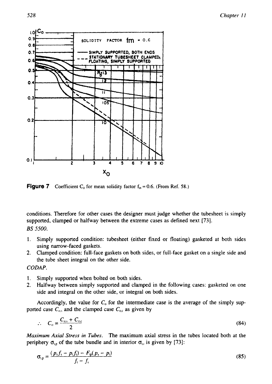
The values of coefficient
C,
are given in Fig.
7
for a mean solidity factor of
0.6.
The coefficient
AC, gives the correction for other values of the solidity factor. It can be seen from Fig. 7 that
values for
CO
are given only for two limiting cases of tube-sheet edge conditions:
(1)
simply
supported
(Z=
0),
and
(2)
clamped tube sheet
(Z=
-).
No
credit is given for the other edge
528
Chapter
I1
SOLIDITY
FACTOR
fm
-
0.6
0.0
0.7
-
SIMPLY
SUPPORTED, 80TH ENDS
Figure
7
Coefficient CO
for
mean
solidity
factor
f,,,
=
0.6.
(From Ref.
58.)
conditions. Therefore for other cases the designer must judge whether the tubesheet is simply
supported, clamped or halfway between the extreme cases as defined next
[73].
BS
5500.
1.
Simply supported condition: tubesheet (either fixed or floating) gasketed at both sides
using narrow-faced gaskets.
2.
Clamped condition: full-face gaskets on both sides, or full-face gasket on a single side and
the tube sheet integral on the other side.
CODAP.
1.
Simply supported when bolted on both sides.
2,
Halfway between simply supported and clamped in the following cases: gasketed on one
side and integral on the other side, or integral on both sides.
Accordingly, the value for
CO
for the intermediate case is the average
of
the simply sup-
ported case
CO,,
and the clamped case
CO,,
as given by
:.
CO
=
cos
+
c0,c
(84)
2
Maximum Axial Stress in Tubes.
The maximum axial stress in the tubes located both at the
periphery
o,,
of
the tube bundle and in interior
O,i
is given by
[73]:
529
Mechanical Design
of
Heat Exchangers
(86)
The coefficients
F,,
and
F,,
are analogous
to coefficient
C,
and are given by curves
[
18,581 that
depend on parameters
X,
and
RD.
3.5
U-Tube Tube-Sheet Formula
BS
5500
For U-tube exchangers, the design method
is
simpler since the tubes do not act as an elastic
foundation. Hence, the CODAP formula for the floating head exchanger can be used by setting
X,
=
0
in the tube-sheet formula. This is done in codes/standards such as
ISO,
BS
5500,
and
CODAP. The tube-sheet thickness formula to resist bending is given by
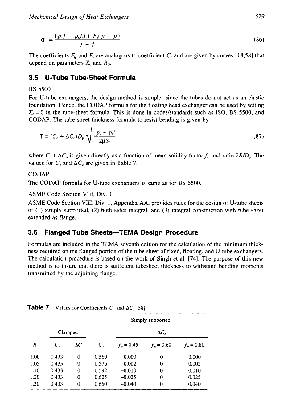
where
C,,
+
AC,
is given directly as a function of mean solidity factorf, and ratio
2RID,.
The
values for
CO
and
AC,
are given in Table
7.
CODAP
The CODAP formula for U-tube exchangers is same as for
BS
5500.
ASME Code Section
VIII,
Div.
1
ASME Code Section
VIII,
Div.
1,
Appendix AA, provides rules for the design
of
U-tube sheets
of
(1)
simply supported,
(2)
both sides integral, and
(3)
integral construction with tube sheet
extended as flange.
3.6
Flanged Tube Sheets-TEMA Design Procedure
Formulas are included in the TEMA seventh edition for the calculation of the minimum thick-
ness required on the flanged portion of the tube sheet of fixed, floating, and U-tube exchangers.
The calculation procedure is based on the work of Singh et al.
[74],
The purpose of this new
method is to insure that there is sufficient tubesheet thickness to withstand bending moments
transmitted by the adjoining flange.
Table
7
Values for Coefficients
CO
and
ACo
[58]
~~
Simply supported
Clamped
ACO
R
C,
ACo
CO
fm=0.45
fm
=
0.60
fm
=
0.80
1.00
0.433
0
0.560
0.000
0
0.000
1.05
0.433
0
0.576
-0.002
0
0.002
1.10
0.433
0
0.592
-0.010
0
0.010
1.20
0.433
0
0.625
-0.025
0
0.025
1.30 0.433
0
0.660
-0.040
0
0.040
530
Chapter
11
Fixed Tube Sheet or Floating Tube Sheet
The thickness of the portion
of
the tube sheet extended as a flange,
tF,
is given by [74]:
M(rf
-
1
+
3.72 ln(rf)}
&.
=
0.98
S(DT
-
G) (1.0
+
1.86
rf)
where
M
is the bolting moment due either to gasket seating condition or operating conditian,
whichever is greater; if a joint
is
integral (welded connection), then the corresponding edge
moment is zero;
DT
and G are the tubesheet outer diameter and effective gasket diameter as
defined
in
TEMA RCB-7.132, respectively; and
S
is the Code allowable stress at the design
temperature. The quantity
rf
is the ratio of
DT
to G:
U-Tube Tube Sheet
The minimum thickness of the portion of the tube sheet
of
thickness
T
extended as a flange,
T,,
is given by [87]:
where
where
M
is the bolting moment either due to gasket seating condition or operating condition
whichever is greater (if a joint is integral, such as welded connection, then the corresponding
edge moment
is
zero); G has different values for different styles
of
construction (for example,
G is the inside diameter
of
the pressure part for the pressure acting on an integral side
of
a
tube sheet; it is the location
of
the gasket load reaction as defined in the code for the pressure
acting on the gasketed side of a tube sheet, TEMA RCB-7.132);
P
=p,
or
pI
or maximum
differential pressure or as defined in TEMA; and
w
=
0.5
(DT
-
G).
For each pressure loading, the calculation procedure
is
as follows:
1.
Compute
M*
from
Eq.
91, assuming
T,
=
T
(rim and interior tube-sheet thickness equal).
2.
Assume
P
=
p,
or
pt
or maximum differential pressure, as applicable.
3.
Compute the required tube-sheet rim thickness
T,
from
Eq.
90
If
T> T,
and both are set
equal to the computed
T,
then the calculation may be terminated at this point.
4.
If
it
is desired to reduce the rim thickness below
T,
the value
of
T,
arrived at
in
step 3 is
used to calculate a new
M*
in Eq. 91. Next, the calculation returns to step
2.
3.7
Rectangular Tube-Sheet Design
The rectangular tube sheet of a surface condenser is designed as per HE1 Standards [4]. The
basis
of
the rectangular tube-sheet design as per HE1 standards is discussed by Bernstein et al.
531
Mechanical Design
of
Heat Exchangers
a
Waterbox
Wall
=
Load From Uaterbox
M
Moment Development In Waterbox
Wall
\
Jotnt
Tubes
1
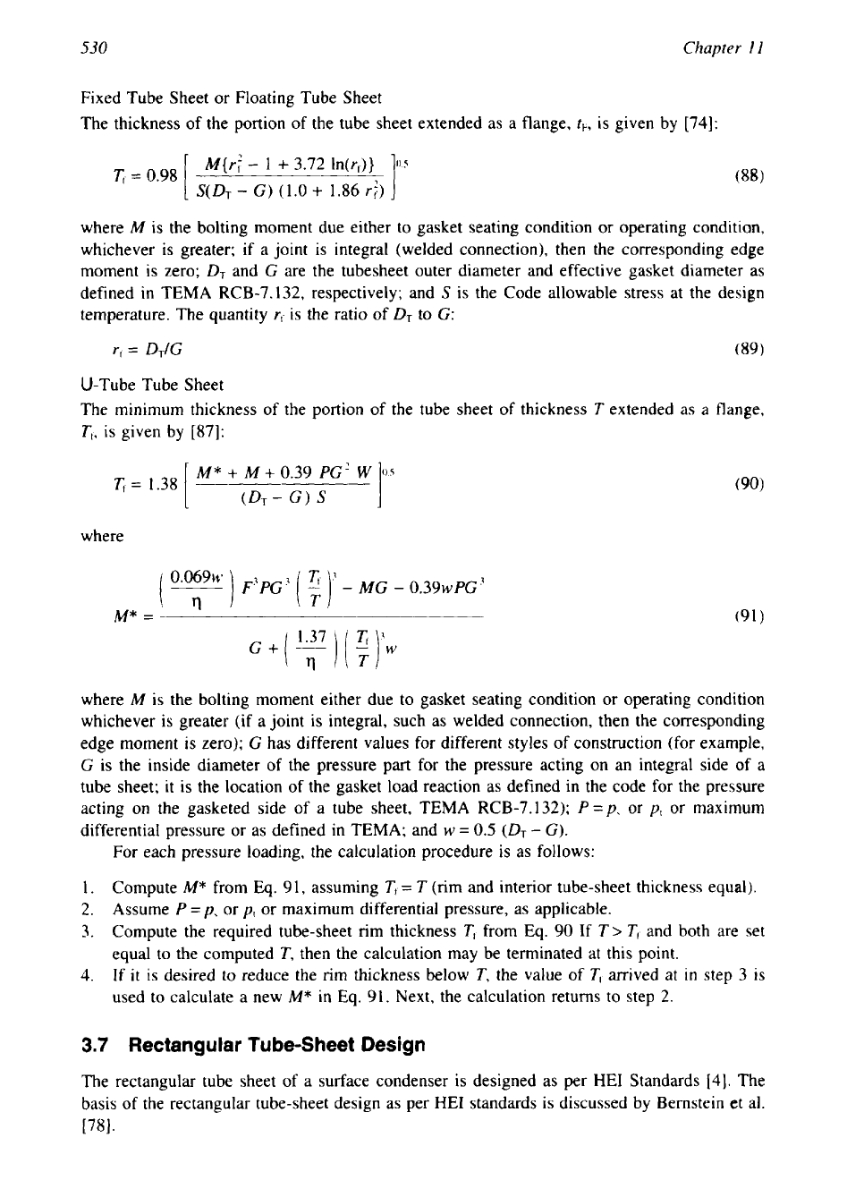
Figure
8
Surface condenser tubesheet connection with waterbox and the shell.
(From
Ref.
78.)
Methods of Tube-Sheet Analysis
Figure
8
shows the plan section of a surface condenser waterbox and shell end assembly with
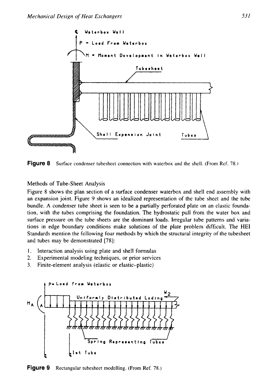
an expansion joint. Figure
9
shows an idealized representation
of
the tube sheet and the tube
bundle. A condenser tube sheet is seen to be a partially perforated plate on an elastic founda-
tion, with the tubes comprising the foundation. The hydrostatic pull from the water box and
surface pressure on the tube sheets are the dominant loads. Irregular tube patterns and varia-
tions in edge boundary conditions make solutions of the plate problem difficult. The
HE1
Standards mention
the
following four methods
by
which the structural integrity of the tubesheet
and tubes may be demonstrated
1781:
1.
Interaction analysis using plate and shell formulas
2.
Experimental modeling techniques, or prior services
3.
Finite-element analysis (elastic or elastic-plastic)
p=Losd
from Waterbox
J
Repreeentlng Tubes
h
blot
Tube
Figure
9
Rectangular tubesheet modelling.
(From
Ref.
78.)
--
532
Chapter
I
I
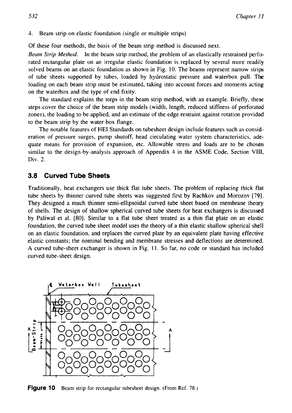
4. Beam strip on elastic foundation (single or multiple strips)
Of these four methods, the basis of the beam strip method is discussed next.
Beam
Strip
Method.
In the beam strip method, the problem of an elastically restrained perfo-
rated rectangular plate on an irregular elastic foundation is replaced by several more readily
solved beams on an elastic foundation as shown in Fig.
10.
The beams represent narrow strips
of
tube sheets supported by tubes, loaded by hydrostatic pressure and waterbox pull. The
loading on each beam strip must be estimated, taking into account forces and moments acting
on the waterbox and the type of end fixity.
The standard explains the steps in the beam strip method, with an example. Briefly, these
steps cover the choice of the beam strip models (width, length, reduced stiffness of perforated
zones), the loading to be applied, and an estimate of the edge restraint against rotation provided
to the beam strip by the water box flange.
The notable features of HE1 Standards on tubesheet design include features such as consid-
eration of pressure surges, pump shutoff, head circulating water system characteristics, ade-
quate means for provision of expansion, etc. Allowable stress and loads are to be chosen
similar to the design-by-analysis approach of Appendix
4
in the
ASME
Code, Section
VIII,
Div.
2.
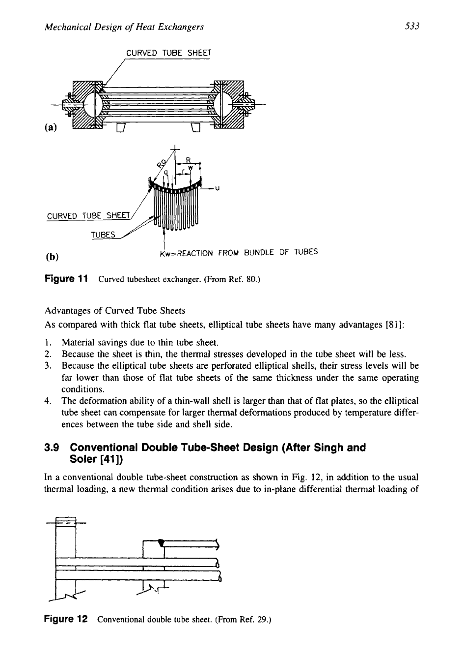
3.8
Curved Tube Sheets
Traditionally, heat exchangers use thick flat tube sheets. The problem of replacing thick flat
tube sheets by thinner curved tube sheets was suggested first by Rachkov and Morozov
[79].
They designed a much thinner semi-ellipsoidal curved tube sheet based on membrane theory
of shells. The design of shallow spherical curved tube sheets for heat exchangers is discussed
by Paliwal et al.
[go].
Similar to a flat tube sheet treated as a thin flat plate on an elastic
foundation, the curved tube sheet model uses the theory
of
a thin elastic shallow spherical shell
on an elastic foundation, and replaces the curved plate by an equivalent plate having effective
elastic constants; the nominal bending and membrane stresses and deflections are determined.
A curved tube-sheet exchanger
is
shown
in
Fig.
11.
So
far,
no
code or standard has included
curved tube-sheet design.
I
&
Wetrrbox
Well
Tuberheet
7
7
00000
1%
000000
i
ooooooooooo
--
-I
L-
oooooooooooo
19
~o~oyo~o~o\
Figure
10
Beam strip for rectangular tubesheet design.
(From
Ref.
78.)
533
Mechanical Design
of
Heat Exchangers
CURVED TUBE
SHEET
CURVED
I
(b)
Kw=REACTION
FROM
BUNDLE
OF
TUBES
Figure
11
Curved tubesheet exchanger.
(From
Ref.
80.)
Advantages of Curved Tube Sheets
As
compared with thick flat tube sheets, elliptical tube sheets have many advantages
[81]:
1.
Material savings due to thin tube sheet.
2.
Because the sheet is thin, the thermal stresses developed in the tube sheet will be less.
3.
Because the elliptical tube sheets are perforated elliptical shells, their stress levels will be
far lower than those of flat tube sheets of the same thickness under the same operating
conditions.
4.
The deformation ability of a thin-wall shell is larger than that of flat plates,
so
the elliptical
tube sheet can compensate for larger thermal deformations produced by temperature differ-
ences between the tube side and shell side.
3.9
Conventional Double Tube-Sheet Design (After Singh and
Soler
[41])
In a conventional double tube-sheet construction as shown in Fig.
12,
in addition to the usual
thermal loading, a new thermal condition arises due to in-plane differential thermal loading of
Figure
12
Conventional double tube sheet.
(From
Ref.
29.)