Kuppan T. Heat Exchanger Design Handbook
Подождите немного. Документ загружается.

514
Chapter
1
I
where
K
is the ratio of axial rigidity of the shell
(K,)
to the axial rigidity of the tube bundle
(N,K,).
The parameter
K
signifies the ratio of the force required to produce a given strain in
the shell to the force necessary to produce the same strain in the tube bundle. It is thus the
measure of the ability of the shell to resist movement of the two tube sheets relative to the
tube bundle
[51].
However, when there is a considerable thermal expansion between the shell
and the tube bundle, the high rigidity of the shell may induce very high thermal stresses in the
tube bundle and the shell. This ability is reduced by the introduction of an expansion joint into
the shell.
An
externally packed floating head exchanger for purposes of tube-sheet design
is
considered as a perfect expansion joint, and for exchangers
so
constructed the value
of
K
is
zero. The expression for the axial rigidity of the shell
K,
is given by:
From the expression for K,(Eq.
2)
and K,(Eq. 12), the resulting expression for
K
is given by
where
D,,
is the shell outside diameter. The expression for axial rigidity of the half shell,
k,,
is
equal to 2K,, and axial rigidity of the half tube,
k,,
is equal to
2K,.
Deflection, Slope, and Bending Moment
From classical thin-plate theory, the deflection of a solid circular plate
of
elastic constants
E*,
v*,
and flexural rigidity
D*
resting on elastic foundation
k,,
subjected to net effective pressure
q(r)
and elastically restrained at its periphery, is given by:
dJw
2
d'w
1
d'w
1
dw
-
q(r)
-+-----+----
drJ
r dr'
r' dr' r' dr
D*
The solution of this equation is of the form
P"
w(r)
=
ABer(x)
+
B
Bei(.u)
+
-
-
A,
+
-
Y
(15)
kw
2
Deflection, slope and bending moment
.u
=
kr
=
42
r
In Eq. 15 Ber(x) and Bei(x) are the modified Bessel functions of the first kind, and
A
and
B
are unknown constants.
At the periphery of the tube sheet (i.e.,
r=R),
x
becomes
X.
It represents the relative
rigidity of the tube bundle with respect to the tube sheet. It may vary from
0
(no tube
in
the
bundle) to above
50
for very stiff tube bundle. The expression for
X
is:
(19)
Mechanical Design
of
Heat Exchangers
51
5
Substituting for
N,
E,
(d
-
t)
by
E&
(Do
-
tJK
and for
E*/(
1
-
v”)
by
q
E/(
1
-
v
’)
and
D,,
=
4
-
t,,
=
2R,
X
becomes
24E,t,(D,
-
t,)
R2(
1
-
v’)
KL
rlE
From
w(r),
one may determine the shear forces, the bending moment, and the slope at any
point in the tube sheet. By employing the Kirchoffs-Kelvin equation, the expression for slope,
dwldr,
and bending moment,
M,
are given by
dw
fj-
dr
d’w
v*
dw
M=D*
-+--
[
dr’
r
dr
The two constants of integration
A
and
B
and the axial displacement of the half shell,
As,
are
determined by the three boundary conditions:
1.
At
r
=
R,
the deflection
w(r)
at the edge of the plate due to bending is zero.
2.
At
r
=
R,
the radial bending moment at the edge of the plate equals the moment exerted
by the rotational spring, i.e.,
where
KO
is the spring constant for half shell. Its value is the sum of the bending rigidities
of the shell and the channel.
3.
The vertical force at the edge,
V,,
is given
by
the net effective force acting on the plate in
terms of net effective pressure q(r):
2n:
(q(r) dr
=
2n;RV,
where
3.3
Tube-Sheet Design as Per TEMA Standards
Tube-Sheet Formula for Bending
As per
RCB-7.131,
the formula for minimum tube-sheet thickness to resist bending
is
given by
FG
3
where
F
is the parameter used to account for the elastic restraint at the edge
of
the tube sheet
due to shell and channel connection,
G
the diameter over which the pressure is acting,
P
the
effective design pressure,
S
the
ASME
Code allowable stress, and
rl
the mean ligament effi-
51
6
Chapter
11
ciency, given in terms of tube layout pattern angle
8
and pitch ratio p/d whose expression
is
given by
=I----
0'785
for
8
=
90"
and 45"
(Pm
-
-I----
0'907
for
8
=
60" and
30"
(26)
(PI4
The values of
F,
P,
and
G
differ for supported and unsupported tube sheets. For a fixed tube-
sheet exchanger,
G
shall be the shell inside diameter. For other types of exchangers refer
to
TEMA
for the definition of
G.
For a fixed tube-sheet exchanger, the effective design pressure,
P,
shall be calculated as per Sections RCB-7.163, RCB-7.164, and RCB-7.165. The definition
of
F
for supported and unsupported tube sheets is discussed next. For all types of tube sheets,
the thickness shall be calculated both for uncorroded and corroded conditions.
Parameter F
Supported Tube Sheet.
1.
Gasketed both sides, e.g., stationary tube sheet and floating tube sheet and floating head
exchanger:
F=
1.0
2.
Integral on both sides or a single side, e.g., stationary tube sheet of fixed tubesheet
ex-
changer and floating head exchanger.
When the tube sheet is integral with both sides or a single side (for fixed tube-sheet
exchangers the gasketed side refers to the tube side),
F
is determined by curve
H
in Fig. RCB-
7.132. The curve is presented in terms of the ratio of wall thickness to internal diameter
(ID)
of the shell or channel, i.e.,
(tlZD),
whichever yields the smaller value of
F.
For the shell-side
integral condition, use the shell
ID
to find
F.
The
H
curve can be represented by:
t
F=
1.0
for
-
5
0.02
ID
t
17
-
100-
ID
-
-
12
t
for
0.05
2
-
>
0.02
ID
t
=
0.8
for
-
>
0.05
ID
(27a)
As
per this condition, the minimum value of
F
is
0.8
and maximum value is 1.0.
Both the tube sheets of the fixed tube-sheet exchanger are satisfied by this condition, and
both the tube sheets shall have the same thickness, unless the provisions of RCB-7.166 are
satisfied.
Note: The
F
value for the tube sheet at the floating head for all configurations is
1.0.
Unsupported Tube Sheet,
For
Example, U-Tube Sheet.
1.
When gasketed at both sides,
F
=
1.25.
2.
For tube sheets integral on both sides or a single side,
F
shall be determined by curve
U
in Fig. RCB-7.132. The curve is presented in terms of the ratio of wall thickness to internal
diameter (ID) of the integral side, i.e., (tlID). The
U
curve can be represented by:
Mechanical Design
of
Heat Exchangers
51
7
F=
1.25
t
for
-
5
0.02
ID
t
17
-
100-
-
-
ID
T
for
0.05
2
-
>
0.02
15 ID
t
=
1.0 for
-
>
0.05
ID
(27b)
As
per this condition, the maximum value of
F
is 1.25 and the minimum value is 1.0.
The term
P
is the effective design pressure where
P
=p,
+
Ph
or
p,
+
Ph;
Ph
is defined as
equivalent bolting pressure when the tubesheet is extended as a flange. The expression for
Ph
is
given by
-6.2M*
Pb
=
____
FG'
where
M*
is defined in Paragraph RCB-7.1342. Expression for
M*
is furnished in the section
on 3.6 flanged tubesheet-TEMA design procedure.
Shear Formula RCB-7.133
The effective tube-sheet thickness
T
to resist shear is given by
0.310,
P
T=
(1
-
d/p)
s
where
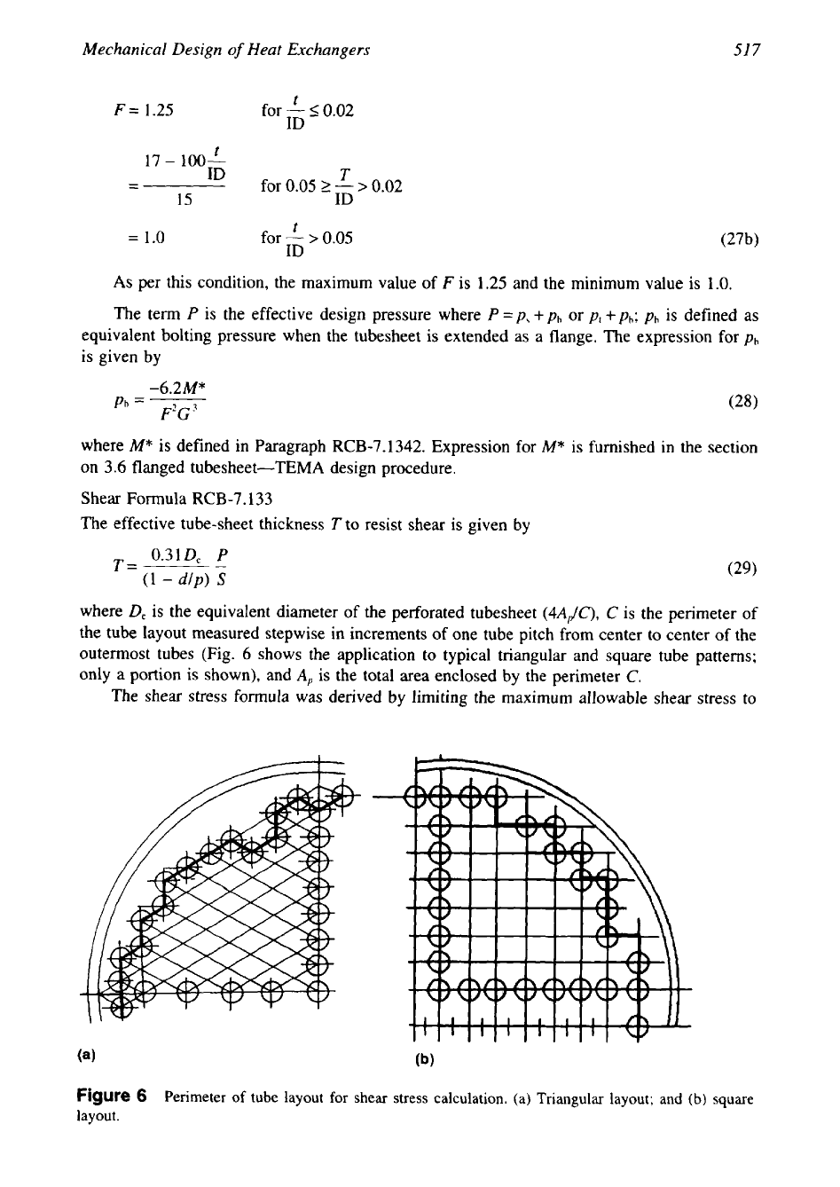
D,
is the equivalent diameter of the perforated tubesheet
(4A,,/C),
C
is the perimeter
of
the tube layout measured stepwise in increments of one tube pitch from center to center of the
outermost tubes (Fig. 6 shows the application to typical triangular and square tube patterns;
only a portion is shown), and
A,
is the total area enclosed by the perimeter
C.
The shear stress formula was derived by limiting the maximum allowable shear stress to
Figure
6
Perimeter of tube layout for shear stress calculation. (a) Triangular layout; and (b) square
layout.
51
8
Chapter
II
0.8
times the Code allowable stress
S.
The shear formula con&& the tube-sheet thickness only
in high-pressure and small-diameter cases. Since the quantities
C
and
A,
are available after the
tube layout is finalized, TEMA provides a formula to check whether shear stress wiii be
controlling the tube-sheet thickness or not. Shear formula will not control the tube-sheet thick-
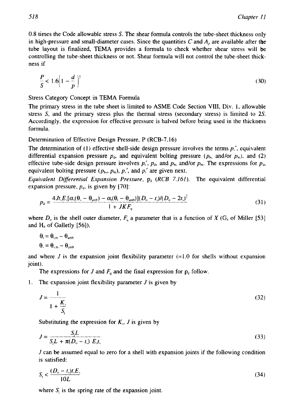
ness if
!<
S
1.6[1
-If
Stress Category Concept in TEMA Formula
The primary stress in the tube sheet is limited to ASME Code Section
VIII,
Div. 1, allowable
stress
S,
and
the
primary stress plus the thermal stress (secondary stress) is limited to
2s.
Accordingly, the expression for effective pressure is halved before being used in the thickness
formula.
Determination of Effective Design Pressure. P (RCB-7.16)
The determination
of
(1) effective shell-side design pressure involves the terms
p,',
equivalent
differential expansion pressure
pd,
and equivalent bolting pressure
(Ph,
andh
Ph[),
and
(2)
effective tube-side design pressure involves
p,',
Pd,
and
Pbs
and/or
Pbl.
The expressions for
pd,
equivalent bolting pressure
(Pb,,
Phr),
p,',
and
p,'
are given next.
Equivalent Diflerential Expansion Pressure,
pd
(RCB
7.161). The equivalent differential
expansion pressure,
pd,
is given by
[70]:
where
D,
is the shell outer diameter,
F,
a parameter that is a function of
X
(G,
of ivliller
[53]
and
&
of Galletly
[56]),
0,
=
@,,m
-
eamh
0,
=
e\.rn
-
edmb
and where
J
is
the expansion joint flexibility parameter (=1.0 for shells without expansion
joint).
The expressions for
J
and
Fq
and the final expression for pd follow.
1.
The expansion joint flexibility parameter
J
is given by
I+-
SJ
Substituting the expression for
K,,
J
is given by
S,L
J=
S,L
+
Z(
Do
-
t,)
E,?,
(33)
J
can be assumed equal to zero for a shell with expansion joints
if
the following condition
is satisfied:
where
SJ
is the spring rate of the expansion join:.
Mechanical Design of Heat Exchangers
51
9
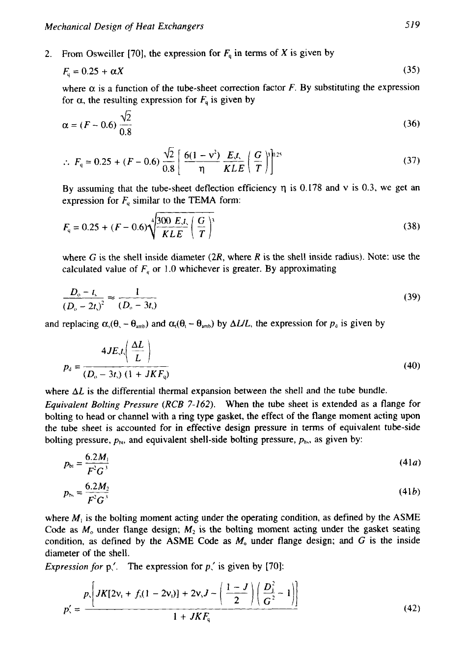
2.
From Osweiller [70], the expression for
Fq
in terms
of
X
is given by
Fq
=
0.25
+
aX
(35)
where
a
is a function
of
the tube-sheet correction factor
F.
By substituting the expression
for
a,
the resulting expression for
Fq
is given by
42
a
=
(F-
0.6)
-
0.8
.*.
Fq
=
0.25
+
(F
-
0.6)
-
6(1
-
v2)
E,t,
(37)
By assuming that the tube-sheet deflection efficiency
q
is
0.178
and
v
is 0.3, we get an
expression for
Fq
similar to the
TEMA
form:
where
G
is the shell inside diameter
(2R,
where
R
is the shell inside radius). Note: use the
calculated value
of
Fq
or
1.0
whichever is greater. By approximating
Do
-
t,
%
1
(39)
(Do
-
2tJ’
(Do
-
3&)
and replacing
a,@,
-
eamb)
and
~(6,
-
eamb)
by
AWL,
the expression for
pd
is given by
where
AL
is the differential thermal expansion between the shell and the tube bundle.
Equivalent Bolting Pressure (RCB
7-162).
When the tube sheet is extended as a flange for
bolting to head or channel with a ring type gasket, the effect of the flange moment acting upon
the tube sheet is accounted for in effective design pressure in terms of equivalent tube-side
bolting pressure,
Pbt,
and equivalent shell-side bolting pressure,
Pb\,
as given by:
where
M,
is the bolting moment acting under the operating condition, as defined by the
ASME
Code
as
MO
under flange design;
M2
is
the bolting moment acting under the gasket seating
condition, as defined by the
ASME
Code as
MO
under flange design; and
G
is the inside
diameter of the shell.
Expression
for
p\’.
The expression for
p\’
is given by
[70]:
p;
=
-
1
+
JKF,
520
Chapter
I1
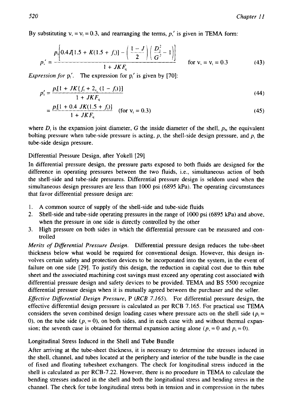
By substituting
v,
=
vI
=
0.3,
and rearranging the terms,
p,I
is given in TEMA form:
Expression
for
p,', The expression for pIf is given by
[70]:
p"l
+
JUft
+
2,,
(1
-
ftHl
p:
=
1
+
JKF,
-
p,[
1
+
0.4
JK(
1.5
+
A)]
(for
v,
=
0.3)
-
1
+
JKF,
(45)
where
D,
is the expansion joint diameter,
G
the inside diameter of the shell,
Pb[
the equivalent
bolting pressure when tube-side pressure is acting,
p,
the shell-side design pressure, and
p(
the
tube-side design pressure.
Differential Pressure Design, after Yokel1
[
291
In differential pressure design, the pressure
parts
exposed to both fluids are designed for the
difference in operating pressures between the two fluids, i.e., simultaneous action of both
the shell-side and tube-side pressures. Differential pressure design is seldom used when the
simultaneous design pressures are less than
1000
psi (6895 kPa). The operating circumstances
that favor differential pressure design are:
1.
A
common source of supply of the shell-side and tube-side fluids
2.
Shell-side and tube-side operating pressures in the range of
1000
psi (6895 kPa) and above,
when the pressure in one side is directly controlled by the other
3.
High pressure on both sides in which the differential pressure can be measured and con-
trolled
Merits
of
Diflerential Pressure Design.
Differential pressure design reduces the tube-sheet
thickness below what would be required for conventional design. However, this design in-
volves certain safety
and
protection devices to be incorporated into the system, in the event of
failure on one side [29]. To justify this design, the reduction in capital cost due to thin tube
sheet and the associated machining cost savings must exceed any operating cost associated with
differential pressure design and safety devices to be provided. TEMA and
BS
5500
recognize
differential pressure design when it is mutually agreed between the purchaser and the seller.
Effective DifSerential Design Pressure,
P
(RCB
7.165).
For differential pressure design, the
effective differential design pressure is calculated as per RCB 7.165. For practical use TEMA
considers the seven combined design loading cases where pressure acts on the shell side
(p,
=
0),
on the tube side
(p,
=
0),
on both sides, and in each case with and without thermal expan-
sion; the seventh case is obtained for thermal expansion acting alone
(p,
=
0
and
p,
=
0).
Longitudinal Stress Induced in the Shell and Tube Bundle
After arriving at the tube-sheet thickness, it is necessary to determine the
stresses
induced in
the shell, channel, and tubes located at the periphery and interior of the tube bundle in the case
of fixed and floating tubesheet exchangers. The check for longitudinal stress induced
in
the
shell is calculated as per RCB-7.22. However, there is no procedure in TEMA to calculate the
bending stresses induced in the shell and both the longitudinal stress and bending stress
in
the
channel. The check for tube longitudinal stress both in tension and in compression in the tubes
521
Mechanical Design
of
Heat Exchangers
located at the periphery of fixed tube-sheet exchangers are calculated as per
RCB-7.23
and
RCB-7.24,
respectively. This is discussed next.
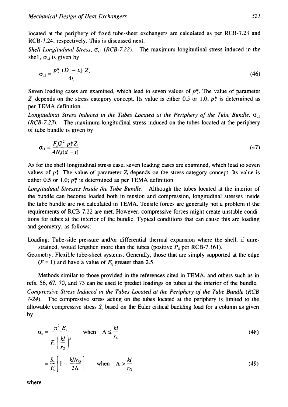
Shell Longitudinal Stress,
o,*l
(RCB-7.22).
The maximum longitudinal stress induced in the
shell,
o,,]
is given by
Seven loading cases are examined, which lead to seven values of
pT.
The value of parameter
Z,
depends on the stress category concept. Its value is either
0.5
or
1.0;
pT
is determined as
per TEMA definition.
Longitudinal Stress Induced in the Tubes Located at the Periphery
of
the Tube Bundle,
(T,.~
(RCB-7.23).
The maximum longitudinal stress induced on the tubes located at the periphery
of tube bundle is given by
FqG'
pTZ,
O,.I
=
4N,t(d
-
t)
(47)
As for the shell longitudinal stress case, seven loading cases are examined, which lead to seven
values of
pT.
The value of parameter
Z,
depends on the stress category concept. Its value is
either
0.5
or
1.0;
pT
is determined as per TEMA definition.
Longitudinal Stresses Inside the Tube Bundle.
Although the tubes located at the interior of
the bundle can become loaded both in tension and compression, longitudinal stresses inside
the tube bundle are not calculated in TEMA. Tensile forces are generally not a problem if the
requirements of
RCB-7.22
are met. However, compressive forces might create unstable condi-
tions for tubes at the interior of the bundle. Typical conditions that can cause this are loading
and geometry, as follows:
Loading: Tube-side pressure and/or differential thermal expansion where the shell, if unre-
strained, would lengthen more than the tubes (positive
Pd
per
RCB-7.161).
Geometry: Flexible tube-sheet systems. Generally, those that are simply supported at the edge
(F=
1)
and have a value of
Fq
greater
than
2.5.
Methods similar to those provided in the references cited in TEMA, and others such as in
refs.
56, 67,
70,
and
73
can be used to predict loadings on tubes at the interior of the bundle.
Compressive Stress Induced in the Tubes Located at the Periphery
of
the Tube Bundle
(RCB
7-24).
The compressive stress acting on the
tubes
located at the periphery is limited to the
allowable compressive stress
S,
based on the Euler critical buckling load for a column
as
given
by
n2
E,
kl
~
or
=
when
AS-
=-4:
[
I--
kl
S
when
A
>
-
(49)
F,
TG
where
522
Chapter
I1
(50)
r,
is the radius of gyration of the tubes,
and
kl
the equivalent unsupported buckling length of the tube,
k
a factor that takes into account
the tube span end conditions,
1
the unsupported tube span between two baffles, and
F,
the
factor of safety
Tube-to-Tube-Sheet Joint Loads (RCB-7.25)
The maximum effective tube-to-tube-sheet joint load,
4,
acting on the tubes located at the
periphery of the tube bundle
is
given by
where
pT
is determined as per TEMA definition. This joint load is to be less than the maximum
allowable joint load calculated as per ASME Code Section VIII, Div.
1.
Maximum
Allowable
Joint
Loads.
In the design of shell and tube heat exchangers other than
U-tube construction, the maximum allowable axial load
on
tube-to-tube-sheet joints shall be
determined in accordance with the code formula. The basis for establishing allowable loads
for tube-to-tube-sheet joints loads is given in ASME Code Appendix AA. In ASME Code,
various joints types are identified by a, b, c, d, e,
f,
g, h, i, j, and
k.
The maximum allowable
joint load
F,,,
is
calculated as follows:
1.
For joint types a,
b,
c, d, e:
FA,
=
AtSaf,
(53)
2. For joint types
f,
g,
h, i, j,
k:
where
A,
is the nominal transverse cross-sectional area of tube wall,
S,
the Code allowable
stresses in tension of tube material at design temperature,& a factor for the percentage
of
tube
expansion length,
fe
=
1.0
for joints made with expanded tubes in grooved tube holes,
d
the
tube outer diameter,
fr
the factor for efficiency of joint, and
fr
the ratio
of
tube-sheet material
yield stress to tube material yield stress.
Refer to ASME Code Section VIII, Div.
1,
for complete details including joint types on
the nomenclature.
TEMA Fixed Tube-Sheet Design with Different Thickness
Fixed tube sheets of different thickness in the same unit are designed as per RCB-7.166.
Considerable savings may be realized when a process dictates a high-quality material at only
one end of a unit where the temperature is very high.
Tubesheet Design as per ASME Code Section
VIII,
Div.
1
A “design-by-formula” procedure for the design of fixed tube sheets of shell and tube heat
exchangers and the connected components is included in the ASME Code, Section VIII, Div.
1, Appendix AA-Nonmandatory. The method follows the approach of Singh and Soler
[41]
and extended by Soler et al. [67] to present a unified treatment for all fixed tube-sheet styles.
523
Mechanical Design
of
Heat Exchangers
The procedure is based on classical thin plate and shell theory. It includes the effect of unperfo-
rated rim of the tube sheet, differential thermal expansion in the radial direction, arbitrary
combinations of material properties and arbitrary joint configurations-three different tube-
sheet, shell, and head configurations, namely, (1) two sides gasketed type construction,
(2)
two sides integral type construction, (3) one side gasketed and the other side integral type
construction-and heat exchanger styles, and the elastic-plastic method, which takes into ac-
count the discontinuity stresses at the tube sheet to shellkhannel joint and considers the possi-
bility of plastic hinges at the shell-tube sheet and channel joints. As a part of the calculations
procedure, charts are provided to evaluate certain parameters. Kuppan [75] provides alternate
charts in place of those presented in ASME CODE, numerical values for certain functions used
to derive the charts that will help to do design calculations without referring the charts, and
extensions of the existing charts for larger values of tubesheet parameter
X.
CODAP
The maximum stress,
6,
in the tube sheet due to bending is given by [73]:
Inverting this equation, the expression for tube-sheet thickness to resist bending is given by
where
Sf
is the CODAP allowable stress,
H,
(X,Z)
the tube-sheet coefficient depending on
parameters
X
and
2
(its expression is given in the Appendix),
p*
the equivalent differential
pressure,
R
the outer tube-sheet radius where shell-side pressure is acting,
T
the tube-sheet
thickness,
p
the minimum ligament efficiency, and
X
and
2
the parameters of the heat ex-
changer (an expression for
X
was given earlier, and
Z
is given in the Appendix).
Parameters
X,
Z,
Ligament Eficiency,
p,
and
p*. The parameter
X
represents the relative
rigidity of the tube bundle with respect to the tube sheet. It may vary from
0
(no tube in the
bundle) to above
50
(very stiff tube bundle). The parameter
Z
represents the elastic rotational
restraint at the periphery of the tube sheet due to channel and shell connection. It may vary
from
0
for the simply supported case to infinity for the clamped case. The expression for
minimum ligament efficiency
p
is given by
where
d
is the tube outer diameter,
p
the tube pitch, and
t
the tube wall thickness.
Equation 57a is applicable to tubes welded to the tubesheet, and Eq. 58b is applicable to
tubes expanded more than
90%
of tube-sheet thickness.
Equivalent Design
Pressure,
p*.
The expression for
p*
for
simultaneous action
of
shell-side
pressure, tube-side pressure and differential thermal expansion (assuming there is an expansion
joint on the shell side) is given by [73]:
p*
=
PX
1
+
JKH,(X,Z)
(59)