Kuppan T. Heat Exchanger Design Handbook
Подождите немного. Документ загружается.

494
Chapter
II
5500
provides design rules for specific well-known and established geometries under design
pressure and temperature loading only. Salient features of design rules of BS
5500
are given
in
Houston
[38].
BS
5.500
Soware
Solution.
ESDU International markets a software package incorporating
BS
5500.
For further details contact:
ESDU International
27
Corsham Street
London NI 6UA, United Kingdom
BS
3274.
This is the specification for tubular heat exchangers for general purposes, design,
construction, and inspection testing of the cylindrical shell and plain tube
heat exchangers.
Shell diameters are 6-42 in, tube lengths 6-16 ft, tube diameters
i-1.5
in.
Type
1
is the fixed
tube sheet (nonremovable tube bundle); type 2
is
the U-tube (removable tube bundle); and type
3
is the floating head (removable tube bundle).
French Codes and Standards on Boiler and Pressure Vessels
Several construction codes and standards are in application in France for the design and con-
struction of pressure components. Steam generators are covered by a set of AFNOR Standards.
Unfired pressure vessels are covered by the CODAP Code. Salient features of design rules
of
French codes and standards on boiler and pressure vessels are reviewed by Thomas et al.
[39].
CODAP
Code.
CODAP Code is applicable to components subjected to pressure whose inter-
nal pressure exceeds
0.5
bar
or
whose external pressure exceeds
0.1
bar
[19].
It is not applica-
ble to piping covered by the SNCT industrial piping code, steam generators covered by the
AFNOR Code, or storage tanks covered by the CODRES, among others. CODAP Code is
updated each year, but there are no formal interpretation or modification request procedures.
Requests are sent to the SNCT Union or to the AFIAP Society. CODAP Code rules are based
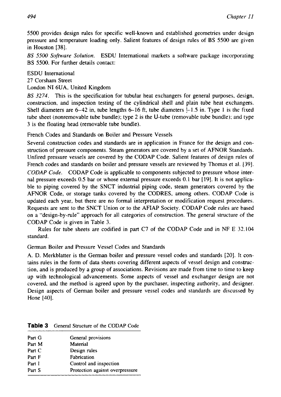
on a “design-by-rule” approach for all categories of construction. The general structure of the
CODAP Code is given in Table
3.
Rules for tube sheets are codified in part
C7
of
the CODAP Code and in NF
E
32.104
standard.
German Boiler and Pressure Vessel Codes and Standards
A. D. Merkblatter is the German boiler and pressure vessel codes and standards
[20].
It con-
tains rules in the form of data sheets covering different aspects of vessel design and construc-
tion, and is produced by a group of associations. Revisions are made from time to time to keep
up with technological advancements. Some aspects of vessel and exchanger design are not
covered, and the method
is
agreed upon by the purchaser, inspecting authority, and designer.
Design aspects of German boiler and pressure vessel codes and standards are discussed by
Hone [40].
Table
3
General Structure
of
the CODAP Code
Part
G
General provisions
Part M Material
Part
c
Design rules
Part
F
Fabrication
Part
I
Control and inspection
Part
s
Protection against overpressure
Mechanical Design
of
Heat Exchangers
495
2
BASICS OF MECHANICAL DESIGN
The structural integrity of pressure vessels and heat exchangers depends on proper mechanical
design arrived at after detailed stress analysis keeping in view all the static, dynamic, steady,
and transient loads. Heat transfer efficiency and fabrication costs of a tubular exchanger are
directly influenced by proper functional and mechanical design. Therefore, an optimum me-
chanical design of various components of heat exchangers is of paramount importance. Me-
chanical design of various pressure-retaining components and some non-pressure-retaining
components of heat exchangers is discussed in this section. Also discussed
in
this section are
the fundamentals of mechanical design and stress analysis, classification of stresses and stress
category concept, allowable stress, weld joint efficiency and joint category, and various design
terms. Important source books on mechanical design of heat exchangers and pressure vessels
are Singh and Soler
[41]
and Escoe
[42]
and on pressure vessels Moss
[43],
Brownell and
Young
[44],
Bednar
[45],
Harvey
[46],
and Chuse
[47],
among others.
2.1
Fundamentals
of
Mechanical Design
Mechanical design involves the design of pressure-retaining and non-pressure-retaining compo-
nents and equipments to withstand the design loads and the deterioration in service
so
that the
equipment will function satisfactorily and reliably throughout its codal life. Mechanical design
is done as per the procedure given in the construction codes and standards. Where no guidance
is provided by the codes and standards, the procedure may be arrived at by mutual agreement
between the purchaser and the fabricator.
Information for Mechanical Design
For mechanical design of shell and tube heat exchangers, certain minimum information is
required
[
141.
The following listing summarizes the minimum information required:
1.
Thermohydraulic design details in the form TEMA or an equivalent specification sheet.
2.
TEMA class, type of TEMA shell, channeldheads.
3.
Shell-side and tube-side passes.
4.
Number, type, size, and layout
of
tubes.
5.
Diameter and length of shell, channelhead, and its configuration.
6.
Design temperatures and pressures.
7.
External pressure if the equipment is under external pressure or
is
under internal vacuum.
8.
Worst-case coincident conditions of temperature and pressure.
9.
Nozzle, wind, and seismic loads, impact loads (including water hammer,
if
any).
10.
Superimposed loads due insulation, piping, stacked units, etc.
11.
Corrosion properties of the fluids and the environment in which the unit will be installed
and the expected service life. This will help to specify corrosion allowances or better
material selection to reduce the material loss due to corrosion.
12.
Materials of construction except tube material, which is arrived at the thermal design
stage.
13.
Fouling characteristics of the streams to
be
handled by the exchanger. This will determine
if closures are required for frequent cleaning of internal parts of the exchanger. Many
fixed tube-sheet heat exchangers, if not specified otherwise, may be of welded head and
shell construction.
14.
Flow
rate to size the nozzles and to determine whether impingement protection is re-
quired.
15.
Special restrictions imposed by the purchaser on available space, piping layout, location
of supports, type of material, servicing conditions, etc.
496
Chapter
I I
16. Construction code and standard to be followed.
17.
Installation-vertical or horizontal.
In addition to these points, plant personnel should consider the following factors that influence
mechanical design:
Considerations of startup, operating, shutdown, and upset conditions that decide tubesheet
thickness
[48].
Handling of lethal or toxic fluids, which demand more stringent welding and NDT require-
ments.
When high-pressure fluid is routed through the tube side, the effect of tube failure in the low-
pressure shell. It is essential to provide overpressure protection on the shell side.
Sequence
of
Decisions
to
Be Made During Mechanical Design.
In addition
to
the informatiam
required at the mechanical design stage as mentioned already, certain decisions are also to
be
made at the mechanical design stage. Soler
[49]
summarizes a typical sequence
of
decisions
that must be made at the mechanical design stage of a heat exchanger design. Some of the
points are:
1.
What kind of connections (welded, flanged, or packed) should be provided at the front
head, tube sheet, and rear head?
2.
What style of flanged joint should be used-for example, ring type gasket or full face
gasket
?
3.
What kind of closures (hemispherical, ellipsoidal, torispherical, conical, etc.) should
be
used?
4.
What combination of load will govern the pressure part design? (Typical loads are shell-
side pressure, tube-side pressure, differential thermal expansion, self-weight, mechani-
cally transmitted vibration and seismic vibration, etc.)
5,
Type and style of openings.
6.
Type
of
nozzle connections, such as self-reinforcing forging stock versus pipe schedule.
7.
Details of vent and drain design.
8.
Minimum bend radii for U-tubes.
9.
Whether an expansion joint is required. If
so,
what is the best type
and
style of the
expansion joint?
10.
Whether installation is horizontal or vertical, to decide the typehtyle of heat exchanger
supports.
11.
Evaluation of the ability
of
the exchanger to withstand operational transients, startup, and
pressure testing.
Each of these decisions and evaluation steps requires a proper adjudication among various
possibilities; many of these considerations require and/or are amenable to mathematical analy-
sis, while others are derived from past experience or experimental data
[49].
Content
of
Mechanical Design of Shell and Tube Heat Exchangers
Mechanical design of shell and tube heat exchangers involves at a minimum the following
components design and the determination of stresses induced in that component:
1.
Shell thickness.
2.
Shell flange and channel flange design.
3.
Dished end calculation.
4.
Design of openings and nozzles.
5.
Tube-sheet thickness. If the differential expansion between shell and tubes is excessive,
then an expansion joint is to be designed and thus final tube-sheet thickness is arrived at.
497
Mechanical Design
of
Heat Exchangers
6.
Shell longitudinal stress and bending stress.
7.
Tube longitudinal stress, both at the tube bundle inside and at the periphery.
8.
Channel longitudinal stress and bending stress.
9.
Tube-to-tube-sheet joint load.
10.
Flat cover thickness.
11.
Design of supports.
B-Jac Program Structure
for
Mechanical Design.
One of the pioneers in developing com-
puter software for thermal and mechanical design of shell and tube heat exchanger is M/s
B-
Jac International, Inc., Midlothian, VA. An insight into the logic of their mechanical design
programs for the design of shell and tube exchangers
is
discussed next.
TEAMS-Mechanical Design
Program.
TEAMS is the mechanical design program
of
B-Jac.
TEAMS covers a wide range of construction alternatives, including most types
of
heads.
flanges, nozzles, and expansion joints. It can also be used for horizontal pressure vessels.
TEAMS conforms with all provisions of the Standards of the Tubular Exchanger Manufactur-
ers Association (TEMA), and appropriate mechanical engineering codes, including ASME and
CODAP. The programs are regularly updated as revisions and addenda are issued by TEMA
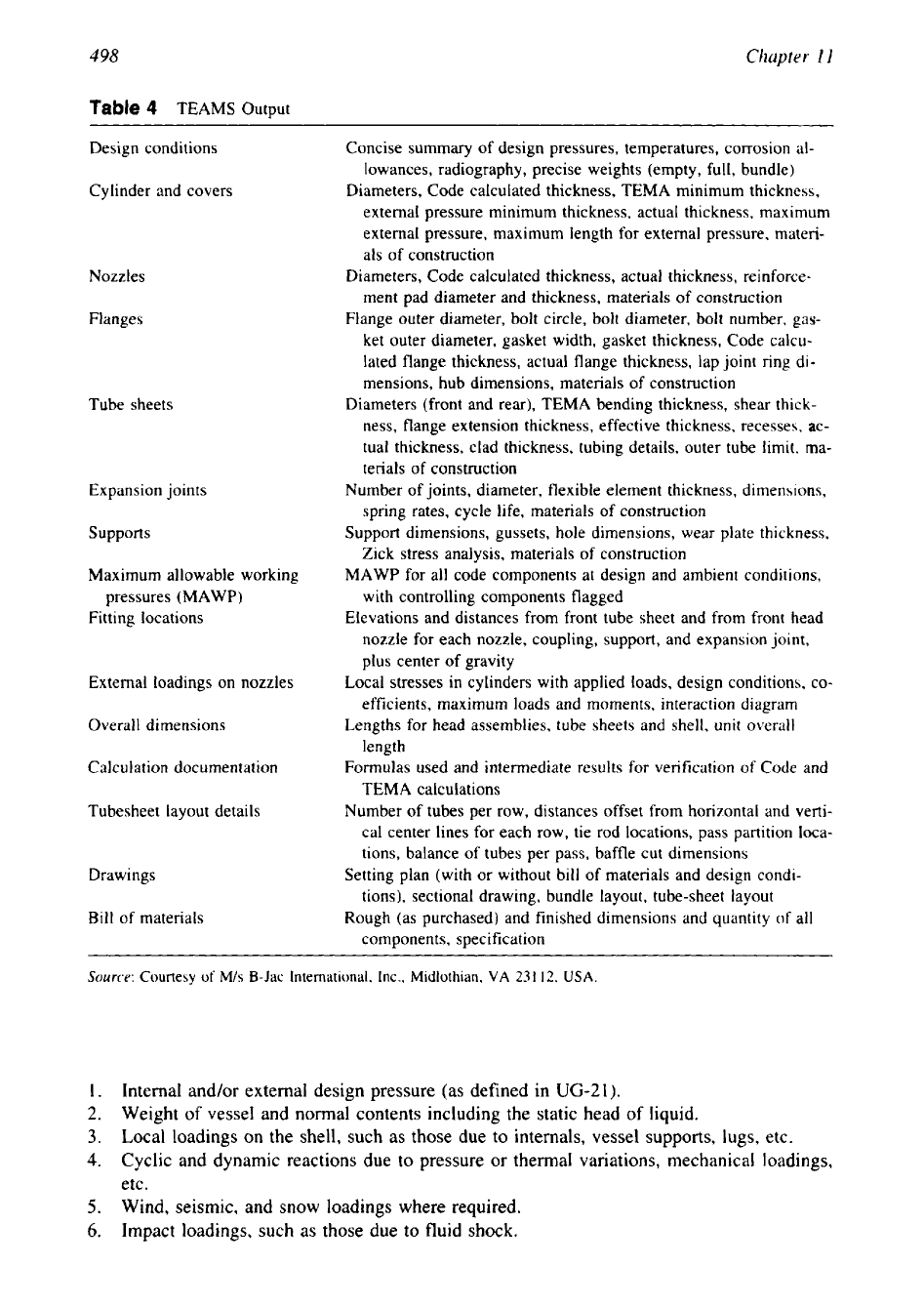
and Code authorities. The contents of TEAMS output are given in Table
4.
Additionally, the following features are available:
1.
Cost estimate summary-Cost of materials, tubing, labor, markup, and selling price.
2.
Material and labor summary-Material costs for major components (shell, front head,
rear head, bundle), assembly costs, labor hours for parts and assembly, major component
weights.
3.
Final assembly summary-Material and labor costs for final assembly operations (e.g.,
x-
ray, testing, inspection, painting).
4.
Bill
of
materials-Rough (as purchased) and finished dimensions and quantity of all com-
ponents, material costs and labor hours, material specification, subcontracted labor.
5.
Part labor details-Labor hours required for each operation (layout, saw, shear, bum,
bevel, drill, machine, mill, form, roll, weld, grind, ream, groove, chamfer) for each compo-
nent.
6.
Assembly labor details-Labor hours to assemble, weld, and grind for the shell compo-
nents, front head components, rear head components, and bundle components.
Mechanical Design Procedure
A typical sequence
of
mechanical design procedures is discussed by Singh
[50].
They are:
1.
Identify applied loadings.
2.
Determine applicable codes and standards.
3.
Select materials of construction (except for tube material, which is selected during
the
thermal design stage).
4.
Compute pressure part thickness and reinforcements.
5.
Select appropriate welding details.
6.
Establish that no thermohydraulic conditions are violated.
7.
Design nonpressure parts.
8.
Design supports.
9.
Select appropriate inspection procedure.
Design Loadings
A list of loadings to be considered in designing a heat exchanger or a pressure vessel
part
is
given in
UG-22
of
ASME
Code Section
VIII,
Div.
1.
They include
498
Chapter
11
Table
4
TEAMS Output
Design conditions
Concise summary of design pressures, temperatures, corrosion
al-
lowances, radiography, precise weights (empty, full, bundle)
Cylinder and covers
Diameters, Code calculated thickness, TEMA minimum thickness,
external pressure minimum thickness, actual thickness, maximum
external pressure, maximum length for external pressure, materi-
als of construction
Nozzles
Diameters, Code calculated thickness, actual thickness, reinforce-
ment pad diameter and thickness, materials of construction
Flanges
Flange outer diameter, bolt circle, bolt diameter, bolt number, gas-
ket outer diameter, gasket width, gasket thickness, Code calcu-
lated flange thickness, actual flange thickness, lap joint ring di-
mensions, hub dimensions, materials
of
construction
Tube sheets
Diameters (front and rear), TEMA bending thickness, shear thick-
ness, flange extension thickness, effective thickness, recesses, ac-
tual thickness, clad thickness, tubing details, outer tube limit, ma-
terials of construction
Expansion joints
Number of joints, diameter, flexible element thickness, dimensions,
spring rates, cycle life, materials of construction
supports
Support dimensions, gussets, hole dimensions, wear plate thickness,
Zick stress analysis, materials of construction
Maximum allowable working
MAWP for all code components at design and ambient conditions,
pressures (MAWP)
with controlling components flagged
Fitting locations
Elevations and distances from front tube sheet and from front head
nozzle for each nozzle, coupling, support, and expansion joint,
plus center
of
gravity
External loadings on nozzles
Local stresses in cylinders with applied loads, design conditions, co-
efficients, maximum loads and moments, interaction diagram
Overall dimensions
Lengths for head assemblies, tube sheets and shell,
unit
overall
length
Calculation documentation
Formulas used and intermediate results for verification of Code and
TEMA calculations
Tubesheet layout details
Number of tubes per row, distances offset from horizontal and verti-
cal center lines
for
each row, tie rod locations, pass partition loca-
tions, balance of tubes per pass, baffle cut dimensions
Drawings
Setting plan (with or without bill of materials and design condi-
tions), sectional drawing, bundle layout, tube-sheet layout
Bill of materials
Rough (as purchased) and finished dimensions and quantity
of
all
components, specification
Source:
Courtesy
of
M/s
B-Jac International, Inc.,
Midlothian,
VA
231
12,
USA.
1.
Internal and/or external design pressure (as defined in
UG-21).
2.
Weight
of
vessel and normal contents including the static head
of
liquid.
3.
Local loadings on the shell, such as those due
to
internals, vessel supports, lugs, etc.
4.
Cyclic and dynamic reactions due to pressure or thermal variations, mechanical loadings,
etc.
5.
Wind, seismic, and snow loadings where required.
6.
Impact loadings, such as those due to fluid shock.
Mechanical
Design
of
Heat Exchangers
499
Topics Covered
in
the Next Sections
In the next sections, the following topics are covered:
1.
Stress analysis, classes, and categories of stress.
2.
Calculation or design of (a) shell thickness, (b) dished end thickness, flat cover thickness,
(d) flange thickness, (e) tube-sheet thickness, (f) shell longitudinal stress, (g) tube longitu-
dinal stress, (h) tube-to-tube-sheet joint loads at the periphery of the tube bundle,
(i)
expan-
sion joint, (j) nozzle openings and reinforcement of nozzle openings, and
(k)
supports.
2
STRESS
ANALYSIS, CLASSES, AND CATEGORIES OF
STRESS
2.1 Stress Analysis
Stress analysis is the determination
of
the relationship between external forces applied to a
vessel and the corresponding stress. The stress analysis of heat exchangers and pressure vessels
is similar to other structural members in that it involves mathematical operations with unknown
forces and displacements. In the evaluation of the stress field
in
heat exchangers and pressure
vessels, the problem is considerably simplified due to these reasons [41]:
(1)
The pressure-
retaining components such as shell, heads, and cones are surfaces of revolution;
(2)
pressure
loading-the primary mechanical loading is spatially uniform;
(3)
the thickness of a pressure
vessel
is
small compared to its characteristic dimensions; and (4) with little accuracy loss,
we can assume that the meridian, tangential, and through thickness directions are principal
directions.
2.2 Classes and Categories
of
Stresses
Classes of stress, categories of stress, and allowable stresses as permitted by Codes are based
on the type of loading that produced them and on the hazard they cause to the structure.
Stress Categories
The combined stresses due to a combination of loads acting simultaneously are called stress
categories.
Stress Classification
The stresses that are present in pressure vessels are separated into various classes
in
accordance
with the types of loads that produced them and the hazard they pose to the vessel. The reason
for classifying stresses into various groups
is
that not all types of stresses require the same
safety factors in protection against failure. Limit analysis theory indicates that some stresses
may be permitted to a higher level than other stresses. Before discussing stress classification,
membrane stress and primary stress are defined.
Membrane Stress
When the thickness is small in comparison with other dimensions
(R,lt>
lO), vessels are
referred to as membranes and the resulting stresses due to contained pressure are called mem-
brane stresses [43]. The membrane
is
assumed to offer no resistance to bending. When the
wall offers resistance to bending, bending stresses occur in addition to membrane stresses.
Primary Stress
Primary stress is a normal stress or a shear stress developed by the imposed loading that is
necessary to satisfy the laws of equilibrium. The basic characteristic
of
a primary stress
is
that
it is not self-limiting. Primary stresses that exceed the yield strength will result
in
plastic
500
Chapter
I1
deformation, gross distortion, or failure. Thermal stress is not classified as a primary stress. It
is classified as a secondary stress only.
Classes of stress and categories of stress are dealt in detail by refs. 41, 43, and 45, among
others.
2.3
Stress Classification
In
the design codes, stresses are classified into five types. They are:
1.
Primary membrane stress,
P,,,
2.
Primary bending stress,
Pb
3. Local membrane stress,
P,.
4.
Secondary stress,
Q
5.
Peak stress,
F
Primary Membrane Stress,
P,,
The component of primary stress that is obtained
by
averaging the stress distribution across
the thickness of the pressure vessel is referred to as the primary membrane stress. It is the
most significant stress class. An important characteristic of the primary membrane stress is
that beyond the yield point, redistribution of stresses in the structure does not take place. It is
remote from discontinuities such as head-shell intersections, nozzles, and supports. Design
codes limit its value
to
the allowable stress for the component material. Examples for primary
membrane stresses are:
1.
Circumferential (hoop) and longitudinal (meridian) stresses due to internal or external
pressures
2.
Stress due to vessel weight
3.
Longitudinal stress due to the bending of the horizontal vessel over the supports
4.
Membrane stress in the nozzle wall within the area of reinforcement due to pressure or
external loads
5.
Stress caused by wind and seismic forces
Primary Bending Stress, Ph
In
contrast to a cylindrical shell, certain structural shapes cannot resist external loadings with-
out bending, and the resulting stress is known as primary bending stress. Primary bending
stress is capable of causing permanent distortion or collapse of the vessel. Some examples of
primary bending stress are
1.
Bending stress due to pressure in a flat cover
2.
Bending stress
in
the crown of a torispherical head due to internal pressure
3.
Bending stress
in
the ligaments of closely spaced openings, such as bending stress
in
the
tube sheet averaged across the ligament
Primary general stresses are divided into primary membrane and primary bending stresses,
and the reason for such a division
so
that the calculated value of a primary bending stress may
be allowed to go higher than that of a primary membrane stress.
Local Membrane Stress, PL
Local (primary) membrane stress is produced either by pressure load alone or by other mechan-
ical loads. It has some self-limiting characteristics. Since the loads are localized, once the yield
strength of the material is reached, the load is redistributed to stiffer portions of the vessel.
Typical examples for local primary membrane stress are stresses at supports and stresses due
to internal pressure at structural discontinuities
[45].
501
Mechanical Design
of
Heat Exchangers
Secondary Stress
Secondary stress is a normal or shear stress arising because of the constraint of adjacent mate-
rial or by self-constraint of the structure. These stresses arise solely to satisfy compatibility
conditions and are not required to satisfy laws of equilibrium. They are self-limiting in nature.
Local yielding can relieve the conditions that lead to the development of these stresses and
limit their maximum value. Failure from secondary stress is not to be expected. The concept
of primary and secondary stresses is not relevant for brittle materials. Two sources of secondary
stresses are
(1)
temperature and
(2)
gross structural discontinuity.
Secondary stresses can be subdivided into two major categories:
(1)
load-actuated secon-
dary stresses and
(2)
temperature-actuated secondary stresses. Examples for these classes are
given next.
Some examples of load actuated secondary stresses are:
1.
Bending stress in a shell where it is connected to a head or to a flange
2.
Bending stress in a shell or a head due to nozzle loads
3.
Bending stress in the knuckle at a head to shell joint
Some examples of temperature-actuated secondary stresses are:
1.
Stresses caused by axial temperature variation in a shell.
2.
Both membrane and bending stresses due to differential thermal expansion between two
adjoining parts of a structure such as nozzle to shell or shell to head.
Moss
[43]
additionally classifies secondary stresses into two groups: membrane and bending.
Examples of secondary membrane stress,
Qm,
are:
1.
Thermal stresses
2.
Membrane stress in the knuckle area of the head
Examples of secondary bending stress,
Qb,
are:
1.
Bending stress at a gross structural discontinuity due to relenting loads only, such as
nozzles and lugs
2.
The nonuniform portion of the stress distribution in a thick-walled vessel due to internal
pressure
Peak Stress,
F
Peak stresses are the additional stresses due to stress concentration in highly localized areas.
They are caused by mechanical and thermal loads and they apply to both limiting and self-
limiting loads. Peak stresses are added to the primary and secondary stresses to give the total
stress at a point.
A
peak stress does not cause any noticeable distortion. The determination of
peak stress is necessary only for fatigue analysis or a source
of
stress corrosion cracking, or it
can be a possible source of brittle fracture
[45].
Peak stress applies to membrane, bending, and
shear stresses. Examples for peak stresses due to thermal and mechanical loads are given next.
Some examples
of
peak stresses due to thermal loads are
1.
Thermal stress in the cladding or weld overlay of a tube sheet, shell, or vessel head
2.
Thermal stresses in a wall caused by a sudden change in the surface temperature (thermal
shock)
Some examples
of
load-actuated peak stresses for specific situations are:
1.
Peak stress in a ligament (uniform ligament pattern)
2.
Stress at a local structural discontinuity
3.
Stress at corner
of
a discontinuity
502
Chapter
1
I
4.
Stress due to notch effect or stress concentration or small radius fillet, hole, or incomplete
penetration
[45]
5.
Additional stresses developed at the fillet at a nozzle-to-shell junction due to internal
pressure or external loads
Discontinuity Stresses
Pressure vessel components and sections usually contain regions of different thickness, mate-
rial, diameter, and abrupt changes in geometry. The juncture at these locations are known
as
“discontinuity” areas. Examples include the skirt junction with the shell/vessel and head and
shell. The stresses induced in the respective parts at or near discontinuity areas are called
discontinuity stresses. Discontinuity stresses are necessary to satisfy compatibility conditions
at discontinuity regions. They are not serious under static loads such as internal pressure with
ductile materials if they are kept with in limits by the design, but they are important under
cyclic loads
[45].
The characteristics of discontinuity stresses are
[43]:
1.
These stresses are local in extent but can
be
of very high magnitude.
2.
Discontinuity stresses are considered as “secondary stresses” and self-limiting,
if
their
extent along the length
is
limited.
3.
In average application, discontinuity stresses will not lead to failure. However, they may
be a major consideration for
(1)
brittle materials and
(2)
high-pressure applications
(>1500
psi).
2.2
Fatigue Analysis
When a vessel is subjected to repeated loading that could cause failure by the development of
a progressive fracture, the vessel is said to
be
in cyclic service.
2.3
Design Methods and Design Criteria
There are two basic design methods used by the codes for the design of heat exchangers and
pressure vessels; these are termed, “design-by-rule” and “design-by-analysis.” The first is based
on experience and does not require a detailed evaluation of all stresses. It gives formulas for
sizing the majority of widely used components. The latter is based on criteria requiring detailed
stress analysis.
ASME Code Section VIII Design Criteria
In general, pressure vessels conforming to the
ASME
Code, Section VIII, Div.
I
are designed
by “design-by-rules” and do
not
require a detailed stress analysis. It is recognized that high
localized and secondary bending stresses may exist but they are allowed for by use of a higher
safety factor. However,
as
per Code rules, all loadings applied to a vessel or its structural
attachments must be considered
(UG-22).
The Code establishes allowable stresses by stating
in Paragraph
UG-23
that the maximum primary membrane stress must not exceed the maxi-
mum allowable stress value in tension. Further, it states that the maximum primary membrane
stress plus primary bending stress may not exceed 1.5 times the allowable stress of the material
in tension. It also recognizes that high localized discontinuity stresses may exist, but the design
rules have been written to limit such stresses to a safe level consistent with experience.
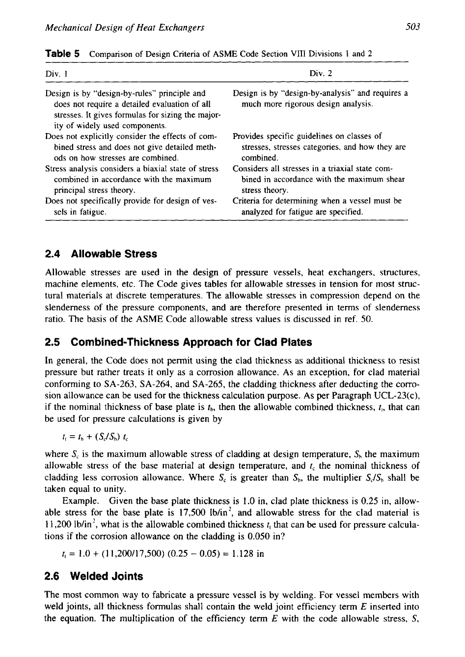
Design Criteria: Comparison of
ASME
Code Section VIII Div.
1
Versus Div.
2
Salient features and differences among Code rules between Div.
1
and Div.
2
are discussed in
ref.
43
and the differences are given in Table
5.
503
Mechanical Design
of
Heat Exchangers
Table
5
Comparison of Design Criteria of
ASME
Code Section VIII Divisions
1
and
2
Design is by “design-by-rules” principle and
Design is by “design-by-analysis” and requires
a
does not require a detailed evaluation of all
much more rigorous design analysis.
stresses. It gives formulas for sizing the major-
ity of widely used components.
Does not explicitly consider the effects of com- Provides specific guidelines
on classes of
bined stress and does not give detailed meth-
stresses, stresses categories, and how they are
ods on how stresses are combined.
combined.
Stress analysis considers a biaxial state of stress Considers all stresses
in a triaxial state com-
combined in accordance with the maximum
bined in accordance with the maximum shear
principal stress theory.
stress theory.
Does not specifically provide for design of ves- Criteria for determining
when a vessel must be
sels in fatigue.
analyzed for fatigue are specified.
2.4
Allowable Stress
Allowable stresses are used in the design of pressure vessels, heat exchangers, structures,
machine elements, etc. The Code gives tables
for
allowable stresses in tension for most struc-
tural materials at discrete temperatures. The allowable stresses in compression depend on the
slenderness of the pressure components, and are therefore presented in terms of slenderness
ratio. The basis of the ASME Code allowable stress values is discussed in ref.
50.
2.5
Combined-Thickness Approach for Clad Plates
In general, the Code does not permit using the clad thickness as additional thickness to resist
pressure but rather treats it only as a corrosion allowance. As an exception, for clad material
conforming to SA-263, SA-264, and SA-265, the cladding thickness after deducting the corro-
sion allowance can be used for the thickness calculation purpose. As per Paragraph UCL-23(c),
if the nominal thickness of base plate is
fh,
then the allowable combined thickness,
t,,
that can
be used for pressure calculations is given by
tt
=
th
+
(Sc/&)
tc
where
S,
is the maximum allowable stress of cladding at design temperature,
S,
the maximum
allowable stress of the base material at design temperature, and
t,
the nominal thickness of
cladding less corrosion allowance. Where
S,
is greater than
&,
the multiplier
&/SI,
shall be
taken equal to unity.
Example.
Given the base plate thickness is 1.0 in, clad plate thickness is
0.25
in,
allow-
able stress for the base plate is 17,500 lb/in2, and allowable stress for the clad material is
11,200 lb/in2, what is the allowable combined thickness
t,
that can be used for pressure calcula-
tions if the corrosion allowance on the cladding is
0.050
in?
t,
=
1.0
+
(1
1,200/17,500) (0.25
-
0.05)
=
1.128
in
2.6
Welded Joints
The most common way to fabricate a pressure vessel is by welding. For vessel members with
weld joints, all thickness formulas shall contain the weld joint efficiency term
E
inserted into
the equation. The multiplication of the efficiency term
E
with the code allowable stress,
S,