Kuppan T. Heat Exchanger Design Handbook
Подождите немного. Документ загружается.

544
Chapter
I1
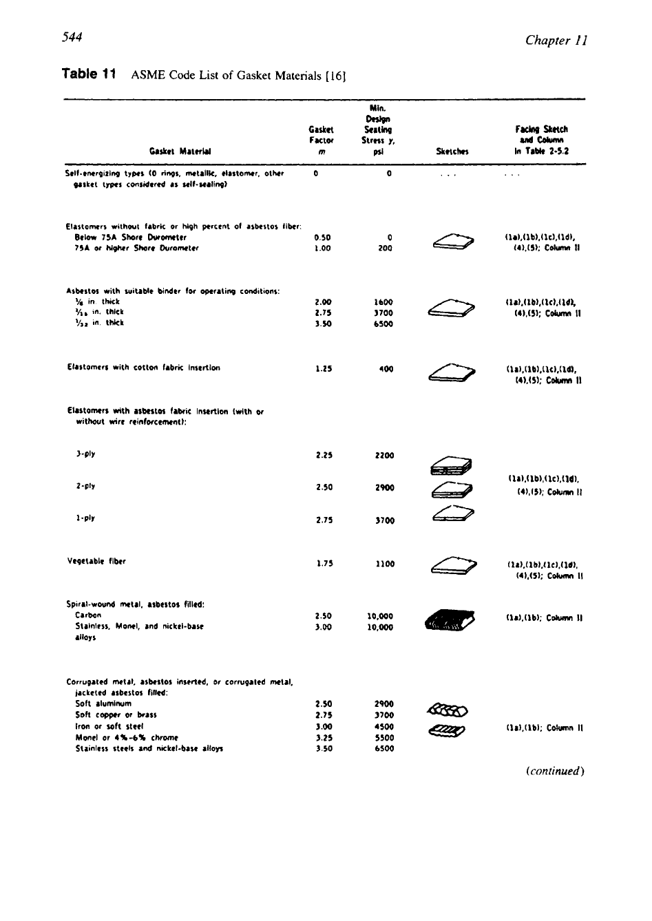
Table
11
ASME
Code
List
of
Gasket Materials
[
161
Min.
Dww
Gasket
Scatbg
FaCh
sketch
Factor
Stress
y,
md
Cdumn
Casket
Material
m
Sketches
In
Table
2-52
Self-enerpizing types
(0
rings,
metallk,
elastomer, other
0
0
***
...
gasket types considered
as
self-sealing)
Elastomers without fabric
or
high percent
of
asbestos fiber:
Below
75A
Shore
Ourofneter
75A
or
higher
Shore
Duromter
Asbestos with witable binder
for
opcraling
conditions:
Ye
in. thick
'hr
in.
thlck
in. thick
ElJstomrrr with cotton fabric Insertion
Elastomers
with asbestos fabric insertlon (with
or
without
wire
reinforcement):
3-PJY
Vepetdble fibrr
Spiral-wound metal, asbestos filled:
Carbon
Stalnless,
Moml, and
nickel-base
dllOyS
Corrugated metal.
asbestos
inscrtcd,
or
corrupatcd
metal,
jacketed asbestos filled:
Soft
aluminum
Soft
copper
or brass
Iron
or
soft
steel
Mont1
of
4%-6%
chrome
Stainless steels and nickel-bare
alloys
0.50
1
.oo
2.00
2.75
3.50
1.25
2.25
2200
2.50 2900
2.75 3700
2.50
10.000 (lJ),(lb);
Cohrmn
II
3.00 10,Ooo
2.50 2900
2.75
3700
em
3
.OO
4500
e37
3.25
5500
3.50
6500
545
Mechanical Design
of
Heat Exchangers
Table
11
Continued
Casket Material
CorrugaLrd
metal:
Soft
&lumltwm
Soft
copper
or
brrrs
Iron
or
wft
steel
Mow1
w
4U4S
chrome
Stainless
steels
and
nickel-bare alloys
Flat
metal,
jackrttd arbertor fillad:
Soft
&luminurn
Soft
copper
or
brrtr
Iron
or
soh
steel
Mwl
44%
chromr
Suinless
steels
and
nicktl-bru alloys
Grooved
metal:
Soft
aluminurn
Soft
copper
or
brass
Iron
or
soft
steel
Mow1
or
4U4U
chrome
Strinkrs
sttels
and
nickel-bar alloys
SolM
bt
mew:
Soft
rlumlnum
Soft
capper
or
brass
Iron
or
soft
rieel
Mod
or
4Y4Y
chrome
Stainless
steels
and
nickrl-base
alloys
Ring jolnt:
Iron
01
soft
stet1
Mow1
or
4x4s
throw
Stainless
$teels
ad
nlckel-bate
alloys
Min.
Casket
Factor
M,)Qn
Seating
Slmr
Y,
and
Column
Facing Sketch
m
pri
Sketcher in
TaMe
2-5.2
2.15
3100
3.00
4500
(
1
a),(
1 b),( Id);
3.25
5500
Column
II
3.50
6500
3.75 7600
3.25
5500
3.50
6500
3.75
7600
3.50
8000
3.75
9000
3.7s
9000
3.21
5500
3.50
6500
3.75
7600
3.75
woo
4.25
10.100
4.00
8800
4.75
13.000
5.50
18,000
6.00
21,800
6.50
26,000
5.90
1B.000
6.00
21,600
6.50
26,000
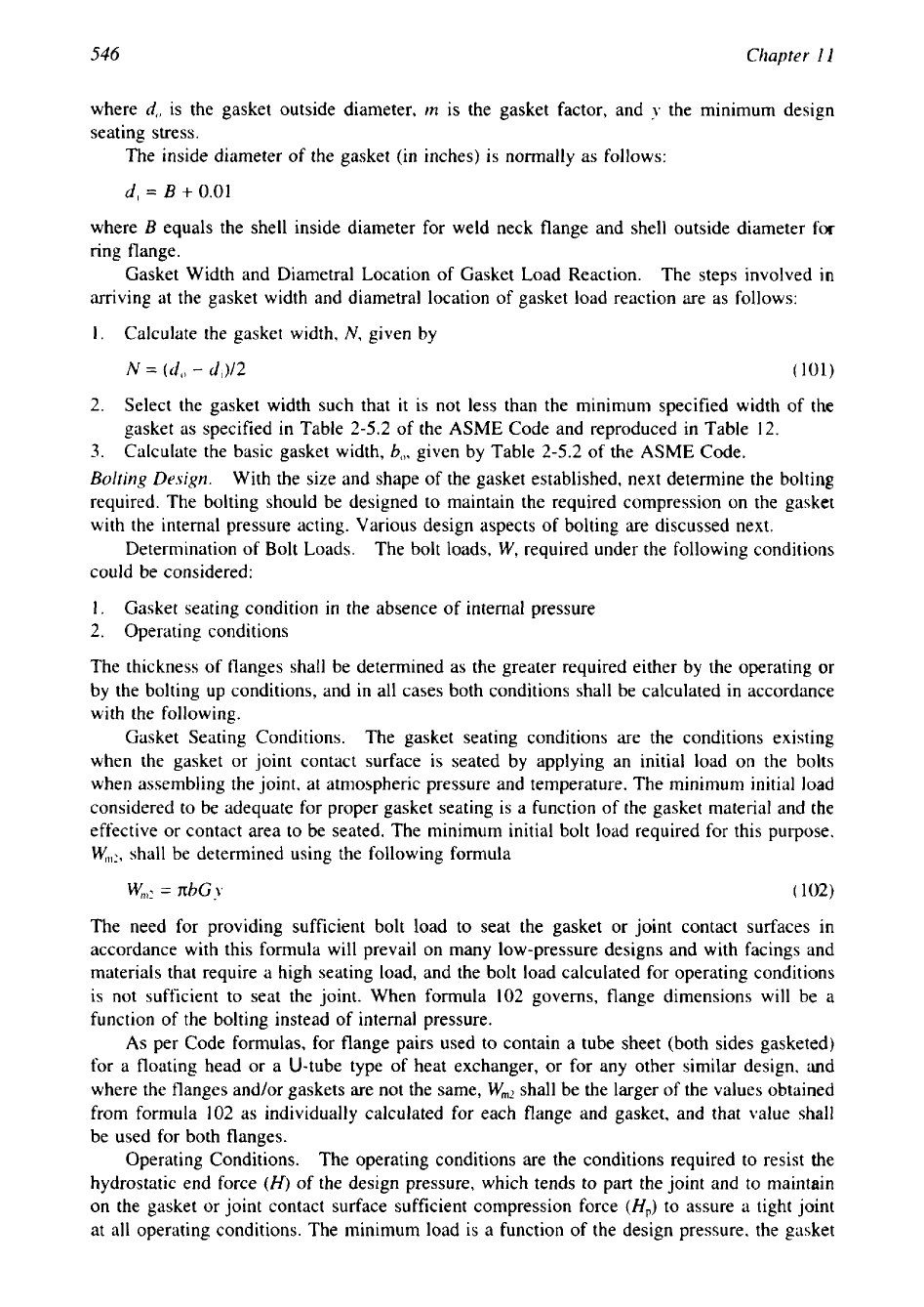
Gasket Dimensions.
A
relationship for making a preliminary estimate of the proportions
of the gasket
may
be derived
as
follows
[41]:
Residual gasket force
=
gasket seating force
-
hydrostatic pressure force
The residual gasket force cannot be less than that required to prevent leakage
of
the internal
fluid under operating pressure. This condition results in the following expression:
I
546
Chapter
1
I
where
d,,
is the gasket outside diameter,
m
is the gasket factor, and
y
the minimum design
seating stress.
The inside diameter of the gasket (in inches) is normally as follows:
d,
=
B
+
0.01
where
B
equals the shell inside diameter for weld neck flange and shell outside diameter
for
ring flange.
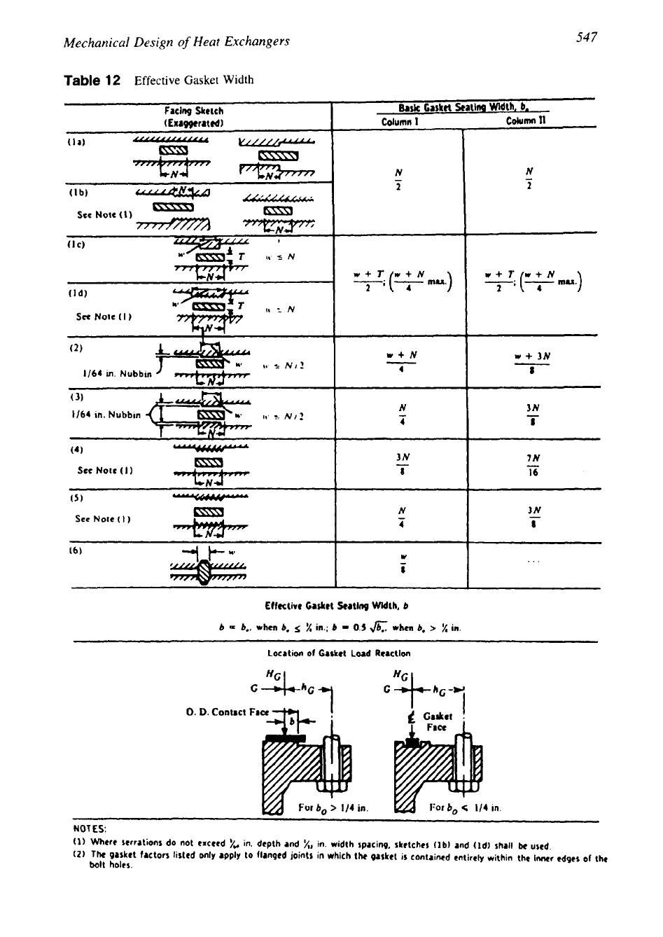
Gasket Width and Diametral Location of Gasket Load Reaction.
The steps involved
in
arriving at the gasket width and diametral location of gasket load reaction are as follows:
1.
Calculate the gasket width,
N,
given by
2.
Select the gasket width such that it is not less than the minimum specified width of the
gasket as specified in Table 2-5.2 of the
ASME
Code and reproduced
in
Table
12.
3.
Calculate the basic gasket width,
b,,,
given by Table 2-5.2 of the
ASME
Code.
Bolting Design.
With the size and shape of the gasket established, next determine the bolting
required. The bolting should be designed to maintain the required compression on the gasket
with the internal pressure acting. Various design aspects of bolting are discussed next.
Determination of Bolt Loads. The
bolt loads,
W,
required under the following conditions
could be considered:
1.
Gasket seating condition
in
the absence of internal pressure
2. Operating conditions
The thickness of flanges shall be determined as the greater required either by the operating
or
by the bolting up conditions, and in all cases both conditions shall be calculated in accordance
with the following.
Gasket Seating Conditions. The gasket seating conditions
are
the conditions existing
when the gasket or joint contact surface is seated by applying an initial load on the bolts
when assembling the joint, at atmospheric pressure and temperature. The minimum initial load
considered to be adequate for proper gasket seating is a function of the gasket material and the
effective
or
contact area to be seated. The minimum initial bolt load required for this purpose,
w,,:,
shall be determined using the following formula
The need for providing sufficient bolt load to seat the gasket or joint contact surfaces in
accordance with this formula will prevail on many low-pressure designs and with facings and
materials that require a high seating load, and the bolt load calculated for operating conditions
is not sufficient to seat the joint. When formula 102 governs, flange dimensions will be a
function of the bolting instead of internal pressure.
As
per Code formulas, for flange pairs used to contain a tube sheet (both sides gasketed)
for a floating head or a U-tube type of heat exchanger,
or
for any other similar design, and
where the flanges and/or gaskets are not the same,
Wmz
shall be the larger of the values obtained
from formula 102 as individually calculated for each flange and gasket, and that value shall
be used for both flanges.
Operating Conditions.
The operating conditions are the conditions required to resist the
hydrostatic end force
(H)
of the design pressure, which tends to part the joint and to maintain
on the gasket or joint contact surface sufficient compression force
(H,)
to assure a tight joint
at all operating conditions. The minimum load is a function of the design pressure, the gasket
-
-
547
Mechanical Design
of
Heat Exchangers
Table
12
Effective Gasket Width
Facing
Sketch
I
Bark
Casket
Satin9
Width,
b.
Column
11
N
-
-
N
2
2
4
w
+
3N
8
N
3N
4
8
7N
-
16
Sec
Nole
(
1
)
srmn
N
4
-
3N
8
(6)
W
-
8
Effectivr
Casket
katlng Width,
b
b
=
b,.
when
b,
5
X
in.;
b
=
0.5
JbT:
when
b,
>
X
in.
Location
of
Gasket
Load
Reaction
-3Lt
c
I
CJSkCI
I
0.
D.
Contact
F8a
in.
NOTES:
(1)
Where
serrations
do
not exceed
yM
in.
depth and
%,
in. width spacing, skrtchcs
flb)
and (Id) shall
k
used.
(2)
The
gasket factors listed only apply to flanged joints
in
which the gasket
is
contained cntirely within the
lwr
cdgts
of
the
bolt
holes.
548
Chapter
11
material, and the effective gasket area or the effective contact area to be kept tight under
pressure. The required bolt load
Wml
for the operating condition is given by
n:
Wml
=
H+
Hp=-G2P+2nbGmP
(103)
4
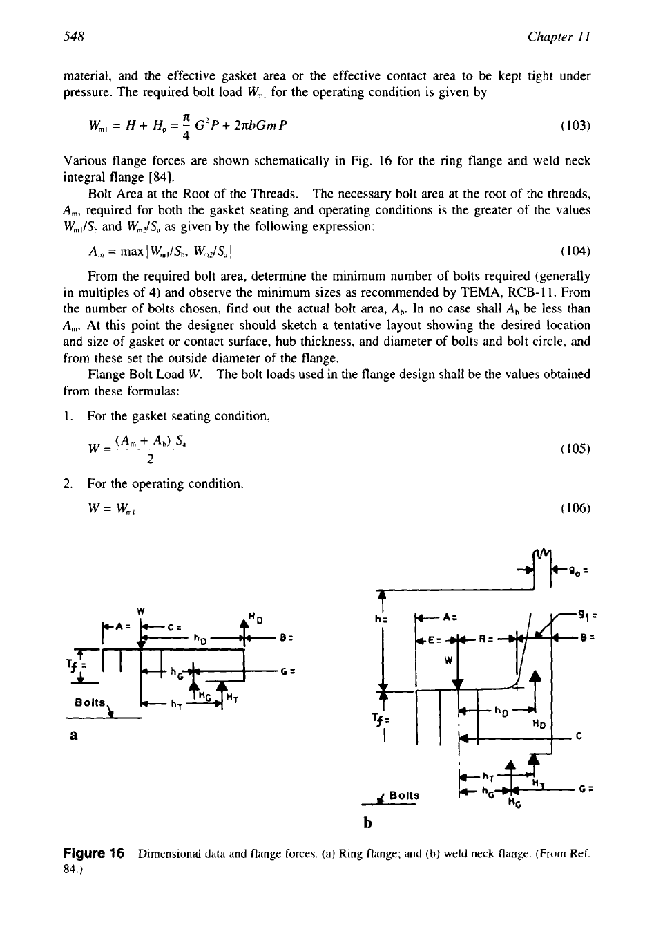
Various flange forces are shown schematically in Fig.
16
for the ring flange and weld neck
integral flange
[
841.
Bolt Area at the Root of the Threads. The necessary
bolt area at the root of the threads,
A,,,,
required for both the gasket seating and operating conditions is the greater
of
the values
w,,,/&
and
W,JS,
as given by the following expression:
A,
=
max
I
Wml/Sh,
W,,,,/S,
1
(
104)
From the required bolt area, determine the minimum number of bolts required (generally
in multiples of 4) and observe the minimum sizes as recommended by
TEMA,
RCB-
1
1.
From
the number
of
bolts chosen, find out the actual bolt area,
Ab.
In no case shall
Ah
be less than
A,,,.
At this point the designer should sketch a tentative layout showing the desired location
and size of gasket or contact surface, hub thickness, and diameter of bolts and bolt circle, and
from these set the outside diameter of the flange.
Flange Bolt Load
W.
The bolt loads used in the flange design shall be the values obtained
from these formulas:
1.
For the gasket seating condition,
2.
For the operating condition,
w
=
W",,
Ig0=
h=
B=
C=
Tf
=
c
T""".l
a
I
C
Figure
16
Dimensional data and flange forces. (a) Ring flange; and
(b)
weld neck flange.
(From
Ref.
84.)
549
Mechanical Design
of
Heat Exchangers
Pitch Circle Diameter.
In general the pitch circle diameter for each particular size of bolt
considered should be kept small, to keep the flange bending moment and flange outside diame-
ter small [85].
Minimum Bolt Size.
Small bolts should
be
avoided wherever possible, owing to the case
with which they may be over stressed by torsion applied with a wrench. Bolts, studs, nuts, and
washers must meet the Code requirements. Appendix 2 of the Code recommends not using
bolts and studs smaller than 0.5 in (12.7 mm). If bolts or studs smaller than
0.5
in (12.7 mm),
alloy steel bolting material must
be
used. Precautions must be taken to avoid overstressing
small-diameter bolts.
TEMA Standards give guidelines for minimum bolt size in RCB-11. The minimum bolt
size is 0.75 in for
R,
0.5 in for C, and 0.625 in for B class exchangers.
Minimum Recommended Bolt Spacing. Bolts should be spaced far enough apart to per-
mit the clearance necessary for socket wrenches and to insure a uniform compression on the
gasket. Likewise, the bolt circle on hubbed or integral flanges should have sufficient diameter
to permit a generous fillet between the back of the flange and hub. Waters-Taylor recommends
a bolt spacing of at least 2.25 times bolt diameters between centers to avoid high stress concen-
tration.
In the TEMA guidelines, the minimum chordal pitch between adjacent bolts and minimum
recommended wrench and nut clearances may be read from TEMA Table D-5.
Maximum Recommended Bolt Spacing. The bolt spacing should not be
so
great as to
result in an appreciable reduction in gasket pressure between bolts. Waters-Taylor recommends
a spacing of 3%
(d
is the nominal diameter of bolt) between bolt hole centers as a reasonable
maximum. An empirical expression given by Taylor Forge and Pipe Works [84] expresses the
maximum bolt pitch
in
the form
61;:
B,,,
=
2d
+
____
(107)
m
+
0.5
where
B,,,
is the maximum bolt spacing for a tight joint (in),
d
the nominal bolt diameter (in),
Tf
the flange thickness (in), and
m
the gasket factor, which is obtained from ASME Code Table
2-5.1. This is included in TEMA,
RCB-
1
1.22.
Load Concentration Factor.
As per TEMA RCB-11.23, when the distance between bolt
centerlines exceeds the recommended
B,,,,
the total flange moment determined shall be multi-
plied by a load concentration factor equal to
[3]:
where
B
is the
centerline-to-centerline
bolt spacing.
Note: To prevent over stressing of bolted flanged connections, the designer should, wher-
ever possible, set the lengths of wrench to be used.
Relaxation of Bolt Stress at Elevated Temperature. A rise in temperature of a flanged
joint causes the bolt and flange stresses to diminish, and on maintaining the joint at tempera-
ture, further reduction in stresses may occur due to creep as time elapses [85]. A multiphase
PVRC elevated temperature program was initiated in 1982 by a task group of the PVRC
Subcommittee on Gasket Testing Elevated Temperature Joint Behaviour, and the committee’s
report is published through WRC Bulletin 391 by Derenne et al. [86].
Flange Design.
After the gasket and bolting design, next determine the flange dimensions
required to withstand the bolt load without exceeding the allowable stress for the flange mate-
rial. The outside diameter of the flange must be large enough to seat the bolt with manufactur-
550
Chapter
I1
ing tolerance. In addition to bolting data, some more details on flange dimensions can be read
from TEMA Table
D-5.
Since the flange design procedure is iterative in the case of integral
weld neck flange and slip-on flange, initially assume a flange thickness. In the case of the ring
flange, a closed-form solution for flange thickness is possible. The next step is to determine
the moment
arm
of the various forces and reactions.
Flange Moments. In the calculation of flange stress, the moment of a load acting on the
flange is the product of the load and the moment
arm.
Various forces acting during the operating condition are the hydrostatic end force on area
inside of the flange,
H,,
the pressure force on the flange face,
HT,
and the gasket
load
under
operating conditions,
HG:
KB’P
HI,
=
___
(
109a)
4
HT
=
H
-
HI,
(
109b)
HG=
W-H
(
109c)
where
W
is bolt load,
W,,,,
or
Wn,,!,
whichever
is
greater. For the operating condition, the flange
moment
M,,
is the sum of the three individual moments
M,,
MT,
and
MG.
Determine the moment
arms
hD,
hT,
and
hG
for flange loads under operating conditions from Table 13 for the three
types of flanges. Calculate
MD
(moment due to
H,),
MT
(moment due to
HT),
and
M,,
(moment
due to
HG)
as given by
MD
=
HDh
1)
(11oa)
MT= HrhT
(I
106)
Mc;
=
HGhG
Woe)
and
M,,
=
M[)
+
MT
+
MG
(111)
For the gasket seating condition, the total flange moment
kf;
(ASME Code uses the term
MO
for moment due to gasket seating condition
also),
which is opposed only by the gasket load
W,
is given by
M:,
W(C
-
G)
=
2
Flange Thickness.
For a ring flange, the flange thickness
t,
required is the greater
of
the
gasket seating condition
or
operating condition, given by
where
Y
is the shape constant, defined in Section
5.2,
Step
5.
Table
13
Moment
Arms
for Flange Loads Under Operating
Conditions
Integral flange
R
+
O.5gl
0.5(R
+
g1
+
h,)
0.5(C
-
G)
Loose
or
ring flange
OS(C
-
B)
0.5(hD
+
h,)
OS(C
-
G)
Lap flange
OS(C
-
B)
OS(C
-
G)
0.5(C
-
G)
Mechanical Design
of
Heat Exchangers
551
For the weld neck integral flange, as mentioned earlier, flange thickness is calculated by
iterative process until such time as the flange stress falls within allowable stress for the flange
material. If not within the limit, increase the flange thickness and continue the steps mentioned
earlier. The stresses induced in the flange shall be determined for both the operating condition
and gasket seating condition, whichever controls. The procedure to determine flange stresses
is listed in the step-by-step procedure given in the Appendix.
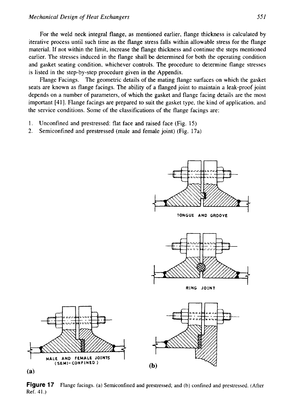
Flange Facings.
The geometric details of the mating flange surfaces on which the gasket
seats are known as flange facings. The ability
of
a flanged joint to maintain a leak-proof joint
depends on a number
of
parameters, of which the gasket and flange facing details are the most
important [41]. Flange facings are prepared to suit the gasket type, the kind of application, and
the service conditions. Some of the classifications
of
the flange facings are:
1.
Unconfined and prestressed: flat face and raised face (Fig.
15)
2.
Semiconfined and prestressed (male and female joint) (Fig. 17a)
nn
I
I
TONGUE AND
GROOVE
RING
JOINT
1
I
I
MALE
AND FEMALE
JOINlS
I
(SEMI-
CONFINED
1
(a)
Figure
17
Flange facings. (a) Semiconfined and prestressed; and
(b)
confined and prestressed. (After
Ref.
41.)
552
Chapter
11
3.
Confined and prestressed: tongue and groove, double step joint, ring joint (Fig. 17b)
4. Self-energizing: 0-rings, metallic, elastomer, etc.
The applicability of various flange facings is discussed in refs. 41 and 44. Flat face aQd
raised face are used for low-pressure applications; the male and female facings have the advan-
tage of confining the gasket, thereby minimizing the possibility of blowout of gaskets. Since
the mating flanges are nonidentical, male and female facings are widely used on heat ex-
changers and not on pipelines. Also, the tongue-and-groove type facings give protection against
deforming soft gaskets into the interior of the vessel. Table
2-5.2
of the ASME Code gives a
list of many commonly used contact facings.
Flange Facing Finish. The type and texture of surface finish are important for leak tight-
ness of a flangedjoint. There are five distinct styles of surface finish that are commonly used
in the industry [41]: rounded nose spiral finish, spiral serrated finish, concentric serrated finish,
smooth finish, and cold water finish.
Requirements for Flange Materials. The material used for flanges must meet the ASME
Code general requirements for materials for pressure retaining parts. Some specific ASME
Code Section VIII, Div. 1 (Appendix
2)
requirements for flange materials include the fol-
lowing:
1. Flanges made from ferritic steel must be given a normalizing or full annealing heat treat-
ment when the thickness of the flange section exceeds
3
in
(76.2
mm).
2.
Material on which welding is to be performed must be proved to be of good weldable
quality.
3.
Welding shall not be performed on steel that has a carbon content higher than 0.35%.
4.
All welding on flange connections must comply with the Code requirements for postweld
heat treatment.
5.
Fabricated hubbed flanges may be machined from a hot-rolled or forged billet
or
a
forged bar.
Rating of Standard Flanges. Standard flanges are rated as 150,300,400,600,900, 1500,
and
2500
lb flanges. TEMA Table D-3 provides dimensions of ANSI standard flanges and
bores of welding neck flanges. Lengths of alloy steel stud bolts for various flange ratings are
furnished in TEMA Table D-4.
Drawback of the Existing Flange Design Procedure
The flange design methods given in the ASME Code and several others base the design criteria
strictly on the flange stress limits [87]. According to Singh [87], the stress-limit-based design
methods do not offer any assurance of sealability; they merely protect the flange from gross
plastic deformation.
A
complete analysis of the bolted joint requires evaluation of the gasket
residual pressure, flange stress, and bolt stress. These requirements commanded the attention
of many committees on bolted joints study.
Bolted Joint Integrity and Intertube Pass leakage in U-Tube Exchangers
An analysis technique
to
determine the structural behavior of the both sides gasketed U-tube
tube-sheet exchanger is studied in ref.
88.
The method also provides procedure to compute the
magnitude of the interpass leakage between the channel pass partition lanes. Some
of
the main
conclusions
of
this study with reference to flange stresses are as follows:
1.
The
flange for the low pressure chamber may be grossly overstressed if sized using the
ASME Code.
2.
The stresses in the high-pressure side flange are generally higher than those predicted by
the ASME Code.
Mechanical Design
of
Heat Exchangers
553
3.
Increasing the bolt prestress increases the stresses in the flanged joint elements. It has,
however, a minor effect in reducing the leakage area.
Pressure Vessel Research Council Activities on Bolted Flanged Connections
The PVRC Committee on Bolted Flanged Connections (BFC) was established in 1985 to im-
prove the ASME design rules for bolted full-face flanged connections. It is led by Chairman
Dr.
K.
H. Hsu of Babcock
&
Wilcox Co. In 1990, the committee developed a 5-year plan and
the goals have recently been organized into six committee assignments [89]:
1.
Implement PVRC gasket constants and test procedure developments.
2.
Issue flange design guidelines considering items such
as
behavior, tightness, transients,
relaxation, etc.
3.
Flange rating parameters for standard flanges.
4.
Design parameters for ASME joints.
5.
Gasket testing for temperature behavior data and test method development.
6.
Flanged joint assembly and interaction effects.
Task
Group
on Flange Parameters Studies (Chairman:
J.
R.
Winter,
Jr.).
This is a task group
to study the parameters and tools for the rating of standard flanges and the design of code
flanges consistent with the committee’s long-range plans. Flange rotation, leak rate, thermal
loads, and gasket performance need to be considered. The emergence of new emissions regula-
tions, new and tighter gaskets, tightness-based gasket constants, and improved analytical tools
all support such a new effort.
5.2
Step-by-step Procedure
for
Integral/Loose/Optional
Flanges Design
The ASME Code procedure for bolted flange joints for integral/loose/optional design is given
here. The design procedure for reverse flange design is not covered. Certain steps may not be
relevant for any one or two of these varieties. The procedure given here is similar to the ASME
Code procedure detailed in the Taylor and Forge Company Bulletin on flange design
[84].
The
flange design procedure for ring flange and weld neck flange is shown in the Working Sheets
furnished
in
Annexures
1
and
2.
The essential steps on bolted flange design are as follows:
1.
Selection of material for flange, gasket, bolts
2.
Calculation of load for gasket seating condition
3.
Calculation of load to withstand hydrostatic pressure known as operating condition
4.
Bolting design and number of bolts decided
5.
Thickness of flange estimation to withstand governing moment
6.
Calculation of stress in the flange and to verify that the calculated stresses are within Code
allowable stress
Data Required
Design pressure,
P
Design temperature,
T
Atmospheric temperature,
T,
Material specification for
Flange
Bolting
Gasket
Code allowable bolt stress
At design temperature,
So