Klocke F. Manufacturing Processes 1: Cutting
Подождите немного. Документ загружается.

9.2 Milling 391
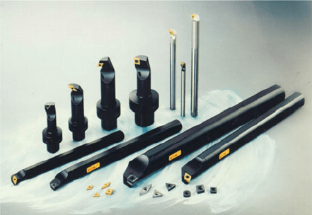
Fig. 9.12 Internal turning: tool design (Source: Sandvik Coromant)
Milling processes are categorized in DIN 8589-3 in accordance with the surface
produced, the tool shape (profile) and kinematics as (including others) [DIN8589c]:
• slab milling,
• circular milling,
• hobbing,
• form milling and
• profile milling.
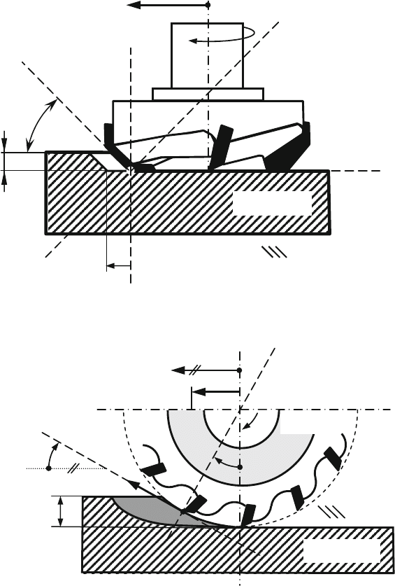
If the workpiece surface is produced by the front face of the tool with the minor
cutting edge, it is called face milling (Fig. 9.13). Analogously, milling processes
in which the surface is manufactured by the cutting edges on the milling cutter
periphery are called peripheral milling (Fig. 9.14).
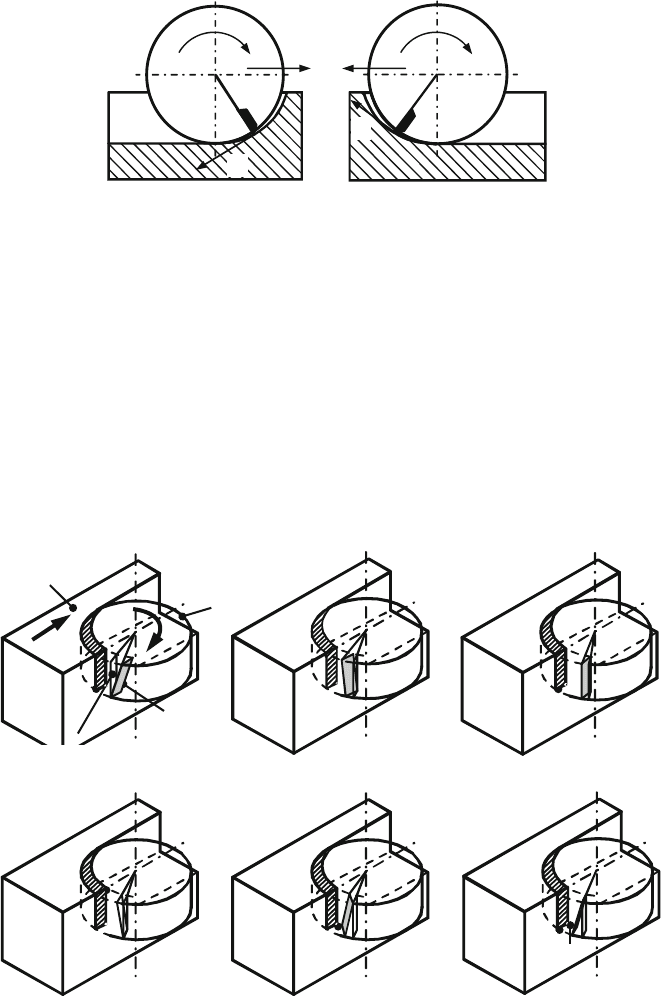
Depending on the tool’s rotation and feed direction, we distinguish further
between up and down milling. In order to distinguish up and down milling from
each other, Fig. 9.15 shows the movements performed with reference to the work-
piece. In practical applications, often the cutting motion is often carried out by the
tool and the feed movement by the workpiece.
In order to distinguish both process variants however, it is advisable to relate the
movements collectively either to the tool to the workpiece. Down milling is shown
in Fig. 9.15, left. At the cutting edge’s point of exit, the cutting speed vector v
c
and
the feed velocity vector v
f
point in different directions. The feed direction angle
between both velocity vectors is ϕ = 180
◦
. In the case of up milling, the cutting
speed vector v
c
and the feed velocity vector v
f
both point in the same direction at
the cutting edge exit point. The feed direction angle is ϕ = 0
◦
. Depending on the
position of the milling tool relative to the workpiece, a milling process can contain
elements of both up and down milling, so a clear classification is not always possi-
ble. In the case of pure down milling, the cutting edge exits with a undeformed chip
thickness of h = 0 mm, i.e. the minimum undeformed chip thickness is undershot
beyond a certain angle of engagement. No definite chip removal occurs at that point,
392 9 Processes with Rotational Primary Movement
Workpiece
Tool
Assumed
working plane P
f
Tool back plane P
p
k
r
Tool cutting edge plane
P
s
a
p
Tool orthogonal plane P
o
n
f
z
v
f
Tool reference plane P
r
Fig. 9.13 Kinematics of face milling
Workpiece
Tool
P
s
≡ P
p
Tool reference plane P
r
v
f
f
z
a
e
v
c
n
P
f
≡ P
o
ϕ
ω
Fig. 9.14 Kinematics of peripheral milling
and solely compressive and frictional processes are occurring. Correspondingly, the
cutting edge enters the workpiece with a undeformed chip thickness of h = 0inthe
case of pure up milling.
The tool orthogonal rake angle γ is composed of a radial component γ
f
and an
axial component γ
p
. As in all other processes, we make a distinction between a
positive (γ
f
and γ
p
> 0
◦
) and a negative (γ
f
and γ
p
< 0
◦
) cutting part geometry.
9.2 Milling 393
Up milling
v
c
v
f
Down milling
v
c
v
f
Fig. 9.15 Up and down milling
In all milling processes, the cutting edges, as opposed to other processes like
turning or drilling, are not constantly being engaged. Rather, at least one cut inter-
ruption occurs per cutting edge during each tool rotation. Because of the constant
cut interruptions, the contact conditions between the tool and workpiece are of par-
ticular importance for the wear properties of the cutting tool materials in addition
to the cutting conditions. Different contacts can result depending on the geometric
conditions determined by the milling cutter diameter, size of cut and cutting part
geometry (Fig. 9.16).
It is particularly inauspicious if the cutting edge point that is the most sensitive to
impact is the first point to make contact with the workpiece. Such “S-contact” can be
SV-Contact
V-Contact
U-Contact
γ
f
<
0°
γ
p
<
0°
γ
f
<
0°
γ
p
>
0°
γ
f
=
0°
γ
p
>
0°
U
V
V
S
Insert
Workpiece
Milling cutter
T-Contact ST-Contact
S-Contact
γ
f
>
0°
γ
p
>
0°
γ
f
>
0°
γ
p
<
0°
γ
f
>
0°
γ
p
=
0°
S
T
T
S
Reference plane
Fig. 9.16 Forms of contact in milling
394 9 Processes with Rotational Primary Movement
avoided by varying the cutting edge geometry and feed rate accordingly. The most
favourable type of contact is “U-contact”, in which the cutting edge point that is
furthest removed from the minor and major cutting edges is the first to make contact
with the workpiece. All other types of point or line contact are regarded as inter-
mediate stages between S-contact and U-contact with respect to impact sensitivity
[Kron54, Beck69, Damm82].
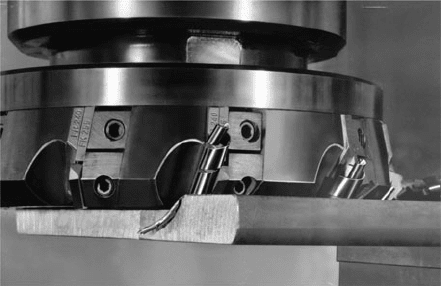
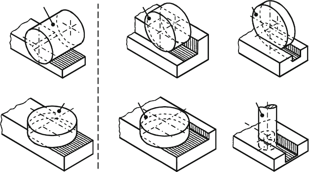
“Helical chip milling” (γ
f
< 0, γ
p
> 0) has become established as a method
for improving chip removal, which is often problematic in the case of rotating tools
(Fig. 9.17).
In comparison to the entry conditions, greater importance is attached to the exit
conditions with respect to wear caused by fractures [Kron54, Okus63, Hosh65,
Beck69, Lola75, Peke78, Peke79, Köll86]. In the case of tool exit with finite unde-
formed chip thickness (e.g. in up milling), tensile stresses can arise in the cutting
edge in the unencumbered state because of resilience, which lead to cutting edge
fracture.
This phenomenon must be taken into account when determining milling strate-
gies. The use of tougher cemented carbides may increase the length of tool life until
failure, but that alone cannot prevent premature failure in the case of unfavourable
exit conditions. In order to improve cutting edge stability, additionally stabilizing
protective chamfers are fitted near the corner and on the cutting edge.
Cutting interruptions mean thermal and dynamic alternate stresses for the cutting
tool material, which can cause comb and parallel cracks and thus lead to cutting edge
fracture. The cutting tool materials used must therefore be very tough, temperature-
resistant and have high edge strength [Vier70].
For steel-working, high-speed steel and tough cemented carbides of machining
application groups P15 to P40 are used; for machining cast iron, NE metals, plastic
and hardened steels types K10 to K30 are used. The cutting tool materials used for
milling were developed with an eye to increased thermal and mechanical alternate
stress and are thus usually not directly comparable with the cutting tool material
types used for turning.
Fig. 9.17 Helical chip milling cutter in use (Source: Walter)
9.2 Milling 395
Further developments in cemented carbides and coating technologies have made
it currently possible to use coated cemented carbides when milling cast irons as well
as steels. When fine milling steels (HB < 300), cermets have also found increas-
ing use. For rough milling grey cast iron, Si
3
N
4
ceramics can be used successfully
with a high material removal rate. Oxidic and mixed ceramics are suitable cutting
tool materials for finish milling grey cast iron, chilled cast iron, case-hardened
steels, heat-treated steels and hardened steels, while in the case of hardened or
high-strength heat-treated steels (> 45 HRC) PCBN is also suitable. Supereutectic
Al alloys, fibre-reinforced plastics and the milling of graphite electrodes for spark
erosion are typical applications of PCD-coated tools when used for milling.
9.2.1 Process Variants, Specific Characteristics and Tools
Milling processes are used most frequently to produce level surfaces (linear feed
movement: slab milling). Figure 9.18 shows the most important slab milling pro-
cesses, which differ by their kinematics and engagement conditions, and designates
the slab milling tools associated with them. In practice, milling processes are usu-
ally named according to the type and form of milling tools used, e.g. plain milling,
end milling, side and face milling, face milling, profile milling etc.
Plain milling cutter
Side and face milling cutter
End milling cutterFace milling cutter
Shell end mill
Fig. 9.18 Slab milling processes
9.2.1.1 Face Milling
In the case of face milling, the width of cut a
e
is much larger than the depth of cut
a
p
, and the workpiece surface is created by the minor cutting edge. If the lead angle
is κ
r
= 90
◦
, this milling process is also referred to as edge milling. In this case, the
workpiece surface is created with both the minor and major cutting edges.
396 9 Processes with Rotational Primary Movement
ϕ = 0°
n
v
c
v
f
−F
f
−F
fn
−F
a
−F
c
−F
cn
ϕ
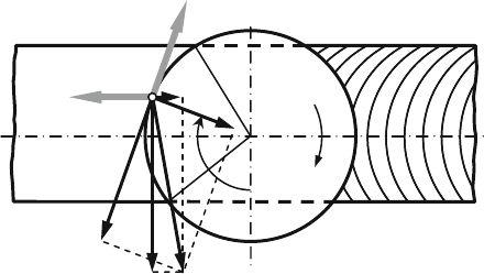
Fig. 9.19 Cutting force components at head face milling, according to KAMM [Kamm77]
According to DIN 6584, the resultant force F involved in milling can be broken
down into an active force F
a
on the working plane and a passive force F
p
perpen-
dicular to the working plane (see also Sect. 3.8.1). The direction of the active force
F
a
depends on the feed direction angle ϕ. The components of the active force can be
related to the direction of the cutting speed v
c
(cutting force F
c
and cutting normal
force F
cn
) or to the direction of the feed velocity v
f
(feed force F
f
and feed normal
force F
fn
)asinFig.9.19.
K
IENZLE’s resultant force equation [Kien52] can also be applied t o milling. For
the components of the resultant force F – cutting force F
c
, cutting normal force F
cn
and passive force F
p
,wehave:
|
F
i
|=k
i
· b ·|
h|
1−m
i
(9.4)
with:
i = c, cn and p
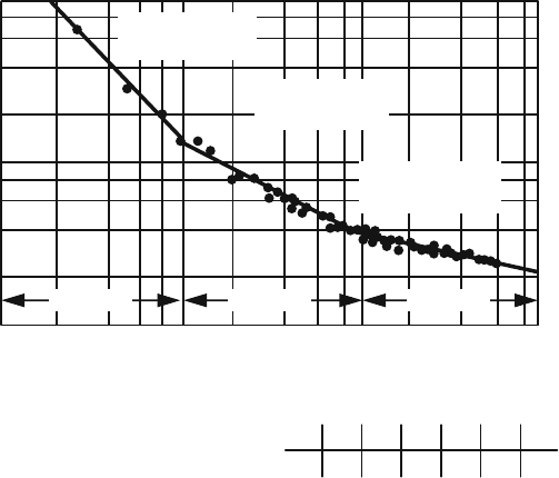
Due to the wide range of undeformed chip thicknesses covered by milling, the
K
IENZLE relation is only valid for certain areas. The range of undeformed chip
thickness of 0.001 < h < 1.0 mm is subdivided into three sections (Fig. 9.20). For
each range, a line can be ascertained, which is defined by the specific resultant force
k
i
and the exponent m
i
:
|k
i
|=k
i1.0,01
·|
h|
−m
i0,01
for 0.001 < h < 0.01 mm
|k
i
|=k
i1.0,1
·|
h|
−m
i0,1
for 0.01 < h < 0.1 mm
|k
i
|=k
i1.1
·|
h|
−m
i
for 0.1 < h < 1.0 mm (9.5)
with:
i = c, cn and p
As long as the characteristic values are known for the existing marginal condi-
tions (material, cutting tool material and cutting conditions), the respective resultant
9.2 Milling 397
1
10
1
10
−2
10
−1
10
0
10
−3
k
c
/ (GPa)
h / (mm)
10
2
Material: Ck45N
Cutting tool material: HW-P25
v
c
= 190 m/min
Range 3
2
4
6
8
2
4
6
8
2468 2468 2468
α
f
6°
ε
r
90°23°
α
p
γ
p
κ
r
−7° 75°
λ
s
−6°
γ
f
−4°
Range 2 Range 1
k
c1.0.01
= 75 MPa
1
– m
c 0.01
= 0.150
k
c1.0.1
= 998 MPa
1
– m
c 0.1
= 0.440
k
c1.1
=
2100 MPa
1
– m
c
=
0.764
Fig. 9.20 Specific cutting force in face slab milling [Kamm77]
force component F
i
can be calculated for milling. To estimate the resultant force
however, characteristic values are often utilized that have been established in turning
processes.
To mill very small, level and right-angled surfaces, grooves with square cross-
sections and long slots, solid face milling cutters made of HSS or cemented carbide
are used, beyond a tool diameter of D = 10−16 mm tools with clamped cemented
carbide indexable inserts and in case of increased requirements on surface qual-
ity, dimensional accuracy and performance milling cutters with soldered cemented
carbide cutting edges [Sack76].
The size and number of teeth of the milling tool are selected based on the dimen-
sions of the workpiece surface to be machined and the drive capacity of the machine.
The tooth pitch of the tool depends on the form and size of the tool, on the avail-
able machine power and on the chip formation of the material. Short-breaking chips
require a small chip space and thus a small pitch. Large cutter heads for cast iron
machining can thus be fitted with up to 200 inserts. In order to prevent chatter-
ing of the tool/workpiece/machine system with the frequency of the cutting edge
engagement, face milling heads are partly manufactured with an uneven pitch on the
periphery.
Face milling heads up to a diameter of D = 250 mm are mounted in the usual
fashion on the tool spindle. Larger face milling cutters are designed in two parts
because of their great weight for better handling during tool change. The base body
remains on the spindle during tool change, so only the ring with the clamped cutting
edges is changed.
398 9 Processes with Rotational Primary Movement
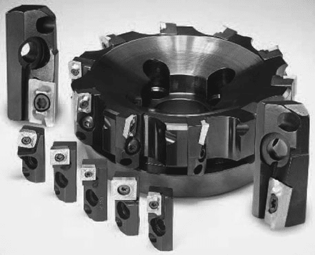
Fig. 9.21 Face milling head with tool cartridges (Source: Kennametal, Hertel)
Another potential way to increase efficiency and universality is the use of face
milling heads with tool cartridges (Fig. 9.21). Depending on the requirements, tool
cartridges can be inserted in a base body that can receive various kinds of index-
able insert (three-corner, four-corner, round), sizes and geometries (e.g. positive,
negative, κ
r
= 90
◦
, κ
r
= 75
◦
, with moulded chip breakers etc.).
In general, steel-working employs positive cutting part geometries and, to
improve chip removal, helical chip geometries. In the case of welded construc-
tions or larger material inhomogeneities, a negative cutting part geometry is more
advantageous for preventing cutting edge fracture. The same is true for machin-
ing materials with high strength and toughness. Milling with cutting ceramics is
generally performed with a negative cutting part geometry.
In order to avoid re-cutting the face milling cutter due to elastic form changes in
the overall system, the milling axis can be tilted by 0.5–1
◦
. However, this sets the
feed direction.
The tool cutting edge angle amounts to κ
r
= 45−75
◦
in face milling (special case:
corner milling κ
r
=90
◦
). It affects to a large extent the size of the active and passive
forces and thus the stability of the milling process, especially when machining thin-
walled parts (e.g. welded gearboxes) or in milling operations on milling and boring
machines with a widely projecting spindle.
Generally, the face milling cutting conditions are selected lower than in turning
processes. Smaller cross-sections of undeformed chip are chosen in particular in
order to keep the dynamic stress on the cutting tool materials low and to prevent
tool fracture.
Face milling is used both for pre-machining and also increasingly for finishing
purposes. Finishing with geometrically defined cutting edges is becoming increas-
ingly important because of the potential of single-machine processing. Finish face
9.2 Milling 399
milling is especially used as a finishing process for large even surfaces with special
surface quality and smoothness requirements when other finishing methods (e.g.
grinding or shaving) are uneconomical or impossible. Such machining problems
usually arise in heavy machine construction, e.g. when producing joining surfaces,
machine tables and guideways on machine tools and when milling sealing faces in
engine and turbine construction.
Indexable inserts for finishing have an active minor cutting edge, i.e. in these
tools the cutting edge angle is κ
r
= 0
◦
, so the chamfer of the minor cutting edge
lies parallel to the workpiece surface. The chamfer length of the minor cutting edge
is generally L
sa
= 2−3 mm, in the case of special wide finish milling tools L
sa
=
10−15 mm. The feed per tooth should not exceed 2/3 of the length of the active
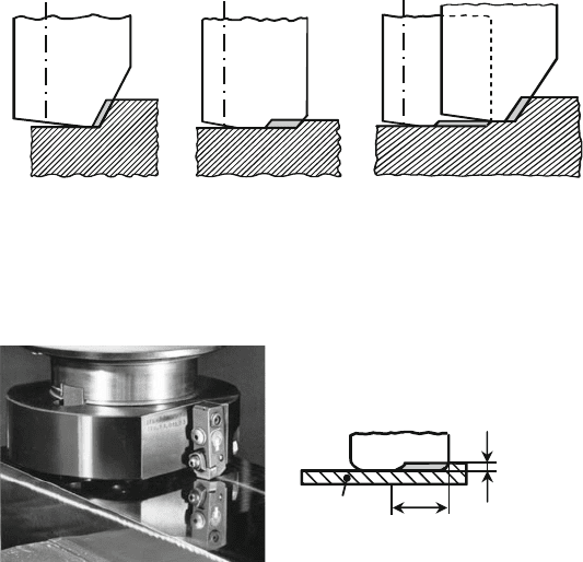
minor cutting edge nad. There are three kinds of finishing tools (Fig. 9.22):
• Conventional finishing face milling cutter which work with small depths of cut
and feeds per tooth and are fitted with a large number of teeth.
• Wide finishing face milling cutters, which are equipped with a small amount of
teeth (1–5) and work with very small depths of cut and high feeds (Fig. 9.23). In
the case of such tools, the minor cutting edge nads are equipped with large radii
to simplify tool pre-adjustment. This helps to obtain a very good surface quality
Finish milling Wide finish milling
Combined process:
Finish milling and wide
finish milling
Fig. 9.22 Processes for fine milling (Source: Siemens)
Workpiece
Insert
Single-tooth milling cutter in use
a
p
= 0.05 mm
Principle of fine milling
with ceramics
f
z
Fig. 9.23 Wide finish milling (fine milling) with ceramics (Source: Feldmühle)
400 9 Processes with Rotational Primary Movement
in cutting, similarly to shell turning. However, the jerk forces are larger than in
conventional finishing face milling, which can result in an axial displacement of
the tool. Ceramics are the predominate cutting t ool materials in this case.
• Face milling with finishing cutting edges and wide finishing cutting edges that
combine the advantages of both methods. The tool is in this case only fitted with
one or two wide finishing cutting edges that are radially set back and that protrude
axially by 0.03–0.05 mm to produce a high surface quality. The width of the
finishing cutting edges should correspond to about one and one half times the
feed per rotation.
For finishing, the pre-adjustment of the cutting edge has increased significance. If
no special, finely adjustable tool holding fixtures are used, all finishing face milling
tools should be ground and lapped prior to use on the machine tool and after fitting
with the cutting edges in order to obtain the necessary face and run-out accuracy
(< 5 μm) corresponding to the required workpiece surface quality. Faulty insert
pre-adjustment increases kinematic roughness and shortens the tool life sometimes
considerably.
The cutting speed is selected high in finishing (e.g. up to v
c
= 300 m/min in
steel-working with cemented carbide) in order to obtain a high surface quality. In
the case of steel, surface finishes of R
t
= 5−10 μm are obtained, in the case of grey
cast iron R
t
= 1−5 μm.
9.2.1.2 Peripheral Milling
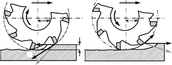
In the case of peripheral milling, the workpiece surface is created by the major cut-
ting edge. There is peripheral down milling and peripheral up milling. In peripheral
down milling, the cutting force acts upon the workpiece (Fig. 9.24), while in periph-
eral up milling it is directed away from the workpiece so that an unstable workpiece
(e.g. a thin steel sheet) can be lifted from the clamping surface or be induced to
chattering.
a
e
f
z
f
z
f
z
n
F
c
F
c
F
f
F
f
v
f
v
f
Down milling Up milling
Vorschub
f
z
n
F
a
F
a
Fig. 9.24 Peripheral up- and down milling
