Klocke F. Manufacturing Processes 1: Cutting
Подождите немного. Документ загружается.

9.3 Drilling 421
γ
γ
f
f/2
f
ng direction
Effective
cutting
direction
Feed direction
Cutting edge
Cutting edge 2
η
e
α
α
f
η
e
β
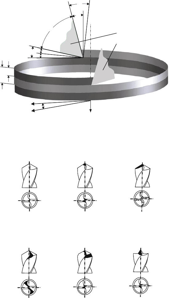
Fig. 9.53 Motion sequence of the major cutting edges by double edged drilling tool
Form D Form E
Taper sleeve grinding
(Polished cone-shaped section
Form A–D)
Picked out
chisel edge
Picked out chisel edge with
adjusted major cutting edge
Split point
Pickedout chisel edge with
faced edge corners
Drill point angle 180° with
centered tip
Form A Form B
Form C
Fig. 9.54 Combination of spiral drills with special polished section from model A till E compared
to taper sleeve grinding, acc. to DIN 1412
422 9 Processes with Rotational Primary Movement
The low self-centring and associated shape and position errors are disadvanta-
geous. In addition, the chisel edge length is increased with increasing drill and core
diameters, such that the resulting high feed forces have an unfavourable effect on
machining accuracy.
In this case and generally only when special demands are placed on the drilling
tool, the drill point is equipped with a s pecial grinding that either complements the
taper sleeve grinding (e.g. core point thinning) or completely reshapes the drill point
(centre point, Fig. 9.54).
The following describes the most important point grindings in accordance with
Fig. 9.54:
• Form A: the taper sleeve grinding with a point-thinned core improves to a great
extent the centrability of the drill and decreases the axial force corresponding to
the chisel edge shortened by about 0.1·D (used in general for Type N beyond
14 mm diameter).
• Form B: the taper sleeve grinding with point-thinned core and corrected rake
angle makes it possible to adjust the rake angle to the machining task. However,
it is customary to reduce the rake angle by about 10
◦
, resulting in a very sta-
ble wedge without hindering chip transport because of a diminished helix angle.
Grinding B is used in cases of high drill stress such as encountered when machin-
ing austenitic manganese steel or when drilling thin-walled aluminium sheets to
reduce deformation.
• Form C: A taper sleeve grinding with a split point in which case the chisel is
completely eliminated. This is especially suitable for deep drill holes. The com-
pressive chisel edge is converted into two small major cutting edges with much
better cutting properties. This type also guarantees good centrability and reduced
feed force.
• Form D: The taper sleeve grinding with point-thinned core and bevelled corners
was specially developed for machining grey-cast iron workpieces, the hard, abra-
sive casting skin of which stresses the sensitive corner to a particularly large
extent. Here, a second taper sleeve grinding with a smaller drill-point angle pro-
vides a remedy in that it helps improve heat conduction and counters increased
wear by increasing its surface area.
• Form E: drill-point angle 180
◦
with centred tip, used when centric drilling must
be guaranteed or when round and burr-free drill holes are to be made in alu-
minium sheets. After total penetration of the centring cone, both major cutting
edges simultaneously cut to their full length, and the corners can support them-
selves immediately on the drill hole wall with the lands. The drill exits again by
the entire major cutting edge, whereby a ring-shaped disc is cut out with minimal
burr formation.
The four-face grinding, a taper sleeve grinding with a secondary face, is men-
tionable despite the fact that it is not standardized inasmuch as it is used when
drilling below 1.5 mm diameters or with cemented carbide drills, since in this case
the tapered sleeve grind causes difficulties.
9.3 Drilling 423
The special working conditions of a drilling tool place high demands on the
cutting tool material with respect to hardness, toughness, wear resistance and insen-
sitivity against thermal alternate stresses. Frequently, HSS is used as a cutting tool
material. According to DIN 1414-1, high speed steels for drilling tools, contain 6%
tungsten, 5% molybdenum, 2% vanadium (HS6-5-2) and for higher stresses 5%
cobalt (HS6-5-2-5). The tools are hardened, topically treated (nitrated) and often
equipped with wear-preventing coatings.
Solid cemented carbide drills are also used however. The advantages of cemented
carbides are their high hardness, compressive strength and high-temperature wear
resistance. Cemented carbides have the same hardness at 1000
◦
C as high speed steel
at room temperature. As a rule of thumb, the cutting speed v
c
can only be increased
by a factor of three. Beyond that, the machining process can continue with a feed
f that is at least 30% higher. Besides this increase in cutting conditions, the tool
life travel path L
f
can be extended by a factor of three. Due to their high Young’s
modules, cemented carbide drills are much more torsion-stiff than HSS tools.
Due to their high hardness and low toughness compared to HSS tools, their use
is technically meaningful and economical only on machine tools that fulfil the min-
imum requirements regarding accuracy, power, cooling and stiffness. One example
for precision requirements is the concentricity of the drilling process. The total
radial deviation measurable at t he cutting edges of the drill is the result of the sum
of each radial deviation of the machine spindle, interface, tool holder and tool. In
current practice, the t ool holder has the highest share. If the minimum requirements
cannot be fulfilled, HSS drills are still preferred, not the least because of their lower
price.
Drilling as a machining process has several peculiarities which we will exam-
ine in the following. In comparison to internal turning, drilling with spiral drills
produces a greater surface finish on the drill hole wall, which is the result of the
comparatively low cutting speed, the low torsion and bending stiffness of the tool
and chip transport [Spur60]. Moreover, spiral drills are subject not only to flank face
and crater wear but also chisel edge wear, land wear and corner wear.
In the case of the spiral drill, total tool wear is composed basically of
• flank face wear,
• crater wear,
• land wear,
• chisel edge wear and
• corner wear
and leads ultimately to relative or absolute disruption of the tool.
Relative disruption is characterized by the fact that beyond a certain drilling
length the machining output no longer correspond to the requirements. In the case of
absolute disruption, the HSS tool becomes completely unusable because of thermal
induced failure of the tool cutting edge or because of tool fracture.
One essential tool life criterion in drilling is reaching pre-given limits in the case
of dimension and shape faults (relative disruption). Wear on the corner and on the
lands is frequently responsible for this. Due to the maximum cutting speed on the
424 9 Processes with Rotational Primary Movement
outer diameter, the corner is especially stressed. This is where HSS tool often fail.
On the other hand, the low cutting speed in the chisel edge area often causes built-up
edge formation, which however does not have a dominantly negative effect on the
process sequence nor makes itself perceptible in the output.
The feed influences tool wear much less than the cutting speed, so it will no
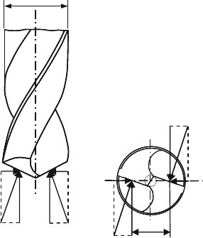
longer be considered here. The forces acting on the spiral drill are represented in
Fig. 9.55 . When drilling with HSS tools, the cutting speed for steels is in the range of
10–40 m/min. A series of studies has shown that here the influence on the resultant
force is small, especially in the case of large drill diameters. In the case of extremely
low or extremely high cutting speeds on the other hand, a considerable increase in
the feed force and cutting moment has been noted, which has an especially large
effect when smaller diameter drills are used.
As in all machining processes with geometrically defined cutting edges, the
resultant force components increase degressively with the feed (Fig. 9.55).
Exhaustive investigations have shown that the surface quality of the drill hole
wall cannot be significantly affected by the drill point grinding. On the other hand,
the dimensional accuracy of the drill hole is dependent on the symmetry of the
grinding, since straying of the tool can only be prevented when there is an extensive
balancing of the radially acting passive force [Spur60].
Different passive forces F
p1
and F
p2
subject the drill to bending and lead to
enlarged drill hole diameters in the output. Such passive forces arise primarily for
tool-related reasons, such as
• unequal major cutting edge lengths,
• unequal drill-point angles,
• unequal tool orthogonal clearances,
• asymmetrical point thinning,
F
f1
F
f2
F
p1
F
p1
F
c1
F
c2
d :
Tool diameter
H : Distance of force-application to
drill axis
F
p2
F
p2
d
2*H
F
c
: Cutting force
F
f
: Feed force
F
p
:
Passive force
Fig. 9.55 Spiral drill forces,
according to [Spur60]

9.3 Drilling 425
Table 9.1 Force components of the major cutting edge, the chisel edge and the land of a spiral
drill
Torque (%) Feed force (%)
Major cutting edge 65–75 17–25
Chisel edge 10–14 65–75
Land 15–20 7–8
• asymmetrical spiral flutes,
• inconsistent cutting edge sharpness and
• radial deviations [Spur60].
The increased cutting and feed forces compared to turning (at otherwise identical
marginal conditions) are due on the one hand to friction of the chips in the bottom of
the groove and on the drill hole wall and on the other hand to the length of the chisel
edge, which should be referred to in consideration of the resultant force more than
the drill diameter. The more narrow the chip space is for chip volume specified by
the cutting conditions the larger are the required cutting moment and the necessary
feed force. Among the feed forces that arise during turning, considerable amounts
of force are also added due to friction on the land and compressive processes in the
area of the chisel edge.
The guidelines in Table 9.1 should be referred to when considering the percent-
age proportion of force of the major cutting edge, the chisel edge and the land of a
spiral drill with respect to torque and feed force:
These percentages were determined by means of step drill experiments. The
torques and feed forces can be determined sequentially only for the major cutting
edges, for the major and chisel edges as well as for the major edge, chisel edge and
land.
9.3.2.2 Cutting Parameters in Drilling
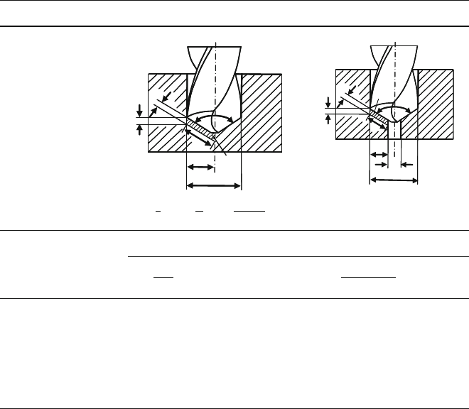
The cross-section of undeformed chip A has a major influence on the resultant force
in drilling. Table 9.2 shows the relevant relations of the cutting parameters in drilling
and the potential calculation of the cross-section of undeformed chip from the feed
component per cutting edge f
z
and the depth of cut a
p
or from the chip thickness h
and chip width b.
9.3.2.3 Calculating Forces, Torque and Power
When Drilling with Spiral Drills
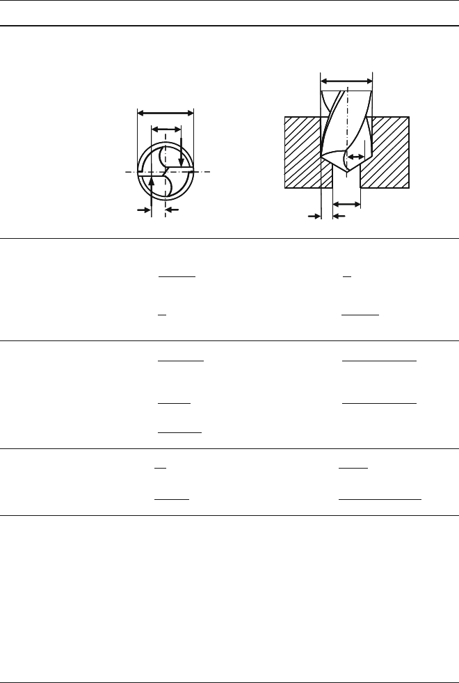
Analogously to the ratios in drilling, we can approximately calculate the cutting
force, feed force and torque for centre drilling and drilling out with spiral drills
with the help of the K
IENZLE equation (Table 9.3). For drilling, it is necessary to
introduce a process factor f
B
in order to take into consideration the altered influences
on the forces that occur in drilling as opposed to turning (e.g. cutting edge shape,
cutting speed etc).
426 9 Processes with Rotational Primary Movement
Table 9.2 Calculation of the cross-section of undeformed chip in drilling
Centre drilling Drilling out
Cutting parameters
a
p
f
z
D
b
h
A
a
p
D
b
A
h
d
f
z
f
z
=
f
z
, κ
r
=
σ
2
, b =
a
p
sin(κ
r
)
, h = f
z
· sin(κ
r
)
A = f
z
· a
p
= b ·h
Cross-section of
undeformed chip
A =
d ·f
4
A =
(D − d) · f
z
2
D Drill diameter [mm] f Feed [mm]
d Pre-hole diameter [mm] f
z
Feed per cutting edge [mm]
a
p
Depth of cut [mm] κ
r
Lead angle [
◦
]
b Chip width [mm] σ Drill-point angle [
◦
]
h Chip thickness [mm]
z Number of cutting edges
9.3.2.4 Deephole Drilling
Deephole drilling is a machining process used to produce or process drill holes.
Deepholes are drill holes with a diameter between about 1 and 1500 mm and
a drilling depth of about three times the diameter. It is not possible to make a
general distinction between deephole drilling and other “conventional” drilling tech-
niques by means of a universally valid definition or the like. With all deephole
drilling methods, a very large ratio of drilling depth to diameter can be obtained.
Further advantages of deephole drilling compared with customary drilling with spi-
ral drills include above all the higher quality of the drill holes and its excellent
cost-efficiency.
Not only is deephole drilling distinguished from common drilling by its asym-
metrical cutting edge arrangement, but also by the fact that in deephole drilling a
cutting fluid is fed directly to the cutting edges under pressure and that its rinsing
effect is the sole transport mechanism for the incoming chips. The cutting part is
made of cemented carbide, so high cutting speeds can be reached, which in turn
9.3 Drilling 427
Table 9.3 Forces, torque, power required in drilling
Centre drilling Drilling out
Force application H = D/4 H = (D +d)/4
a
p
= D/4 a
p
= (D −d)/4
F
cz
D
2
/D
a
p
F
cz
H
d
a
p
D
Process factor f
B
f
B
= 1 f
B
= 0.95
Cutting force per cutting
edge F
cz
F
cz
=
(D − d)
2
· f
z
· k
c
· f
B
F
cz
=
D
2
· f
z
· k
c
· f
B
Feed force per cutting
edge F
fz
F
fz
=
D
2
· f
z
· k
f
· f
B
F
fz
=
(D − d)
2
· f
z
· k
f
· f
B
Torque M
d
=
F
cz
· z ·D
4000
M
d
=
F
cz
· z ·(D +d)
4000
For z = 2: For z = 2:
M
d
=
F
cz
· D
2000
M
d
=
F
cz
· z ·(D +d)
2000
M
d
=
9554 · P
c
n
Power P
a
=
P
c
η
P
c
=
M
d
· n
9554
P
c
=
F
cz
· v
c
60000
P
c
=
F
cz
· v
c
(1 + d/D)
60000
f
B
Process factor drilling k
f
Specific feed force [N/mm
2
]
H Lever [mm] F
cz
Cutting force per cutting
edge[N]
D External drill diameter [mm] M
d
Torque [Nm]
d Internal drill diameter [mm] P
a
Drive power [kW]
z Number of cutting edges P
c
Cutting power [kW]
f
z
Feed per cutting edge [mm] n Speed [min
–1
]
k
c
Specific cutting force [N/mm
2
] v
c
Cutting speed [m/min]
η Efficiency
428 9 Processes with Rotational Primary Movement
ShankDrill bushing
Workpiece Tool
Bead
Cooling lubricant
chip mixture
Cooling
lubricant
supply
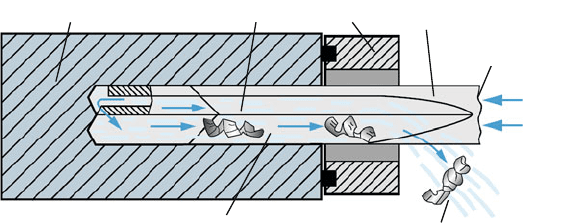
Fig. 9.56 The ELB process for diameters 0.8–40 mm, according to Sandvik
makes it possible to increase the material removal rate. The following three process
variants are used for the industrial production of deep drill holes:
• the single-lip drilling process (ELB process),
• the BTA drilling process,
• the ejector drilling process.
The single-lip drilling process is used in the diameter range of approximately
0.8–40 mm. Figure 9.56 shows the essential characteristics of this method.
The characteristic trait and main advantage of the single-lip drilling process is
that the cutting fluid is supplied by means of one or several drill holes within the
tool and the cutting fluid/chip mixture is safely led away by a longitudinal groove
(bead) on the outside of the tool shank.
Due to the shape of the lead and the large drilling depth/diameter ratio, the drill
is guided on the top face of the workpiece by means of a drill bushing (Fig. 9.56).
This stabilizes the start of drilling. Single-lip deephole drilling tools are used in
manufacturing as solid drills, core drills, countersinks and step drills, whereby full
drilling is the most common case of operation in practice. Basically, the single-lip
drill consists of three components: the drill head, the shank and the clamping sleeve.
In most cases, cemented carbide is used as the cutting tool material, whereby both
solid cemented carbide drill heads as well as drill heads fitted with cemented carbide
are employed.
The BTS process (Boring and Trepanning Association – BTA) was invented at
the end of the 1930s in order to prevent chip scratching on the drill hole wall during
transport and the resulting damage to the surface quality. The attempt to cover the
flute of the single-lip drill outwards resulted however in a drastic reduction of avail-
able chip space, which in turn limited the material removal rate. The solution was
finally discovered by the “Boring and Trepanning Association”, who reversed the
process characteristics of single-lip drilling and supplied the cutting fluid from out-
side by means of a ring-shaped crack between the drill pipe and the wall (Fig. 9.57).
Reflow occurs together with the chips through the cutting jaw and the drill pipe, the
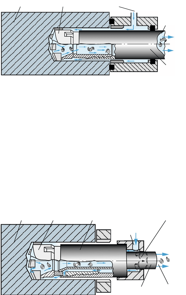
9.3 Drilling 429
Workpiece Tool Cooling lubricant supply
Drill tube
Cooling
lubricant
chip
mixture
Fig. 9.57 The BTA process for diameters of 6–300 mm, according to Sandvik
diameter of which should not be less than 6 mm. The upper diameter for full drilling
tools is around 300 mm and for countersink tools around 1000 mm, whereby these
limits depend to a large extent on the available machine power.
Compared to deephole drilling with single-lip drills, the BTA process has the dis-
advantage that a complicated drill oil supply apparatus is required which takes over
the sealing of the drill pipe. The process requires machines that are much different
than standard drill machines.
The ejector deephole drilling process is utilized for diameters of about
18–250 mm. According to VDI guideline 3209, it is a variant of the BTA process
(Fig. 9.58). Cutting fluid supply is accomplished by means of a ring space between
the drill pipe and an internal pipe (two-pipe process). The cutting fluid enters the
drill head from the side, rinses it and flows back into the internal pipe with the
chips. Part of the cutting fluid is introduced into the internal pipe via a ring noz-
zle. Reflow is made possible by the arising low pressure at the cutting jaw (ejector
Workpiece Tool
Cooling
lubricant chip
mixture
Drill tube
Internal
tube
Ejector effect
Cooling
lubricat
supply
Fig. 9.58 The ejector process for diameters of 18–250 mm, according to Sandvik
430 9 Processes with Rotational Primary Movement
effect). As opposed to the BTA process, sealing against the exit of the cutting fluid is
omitted. A further peculiarity is its cutting edge distribution for reducing the forces
acting on the guide beads as well as the double-sized cutting jaw thus required. The
cutting edge, otherwise continuous from the periphery to the centre, is subdivided
such that two cutting parts are arranged at a time alternating left and right up to the
centre. The consequence of this is that the stress on the guide beads is reduced by
about 10% to a maximum of 50% of the otherwise expected forces, and friction,
heat development and wear are reduced accordingly.
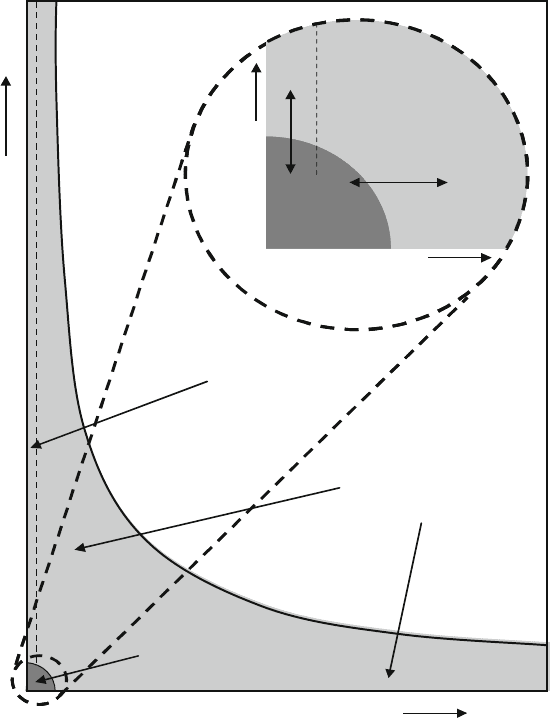
Deephole drilling tools dominate the entire field of inner contours that can be
manufactured by drilling (Fig. 9.59). Other drilling methods and tools are used only
200
0051Diameter (mm)
ELB
Tiefbohren
ELB-Tiefbohren
BTA-
Bereich der konven-
tionellenBohrbearbeitung
Diameter (mm)
BTA
60
Überschneidungsbereich
zum Kurzlochbohren
HM-Bohrer,
Kurzlochbohrer,
Wendelbohrer
200
Length/Diameter
1500
ELB
Deep hole
drilling
ELB - deep hole drilling
BTA - deep hole
drilling
Area of conventional drilling
Length/ Diameter
BTA
60
Short hole drilling
Sintered carbide drill,
Short hole drill,
Twist drill
-
Fig. 9.59 Application of the deep hole tools compared to “conventional” drilling tools, acc.
to VDI guideline 3210
