Klocke F. Manufacturing Processes 1: Cutting
Подождите немного. Документ загружается.

9.2 Milling 401
In the case of peripheral down milling, a table feed drive that is free of play is
necessary in order to prevent vibrations and impacts. While in the case of peripheral
down milling the lead takes place with an approximately full cross-section of unde-
formed chip, in up milling the cross-section of undeformed chip i s slowly increased.
This can lead to material compression and thus to the formation of a poor surface.
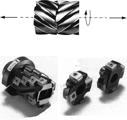
Besides the usual HSS tools, cemented carbide peripheral milling cutters or plain
milling cutters are finding increasing use. When the cutting edges have a coaxial
adjustment, high dynamic stresses come into play because one whole cutting edge
enters into or exits from the material at a time. In the case of helically toothed tools,
the dynamic load can be reduced, but an axial force arises then which can lead to
tool or workpiece displacement. Pitch-induced axial forces can be compensated by
mutually bracing a right-inclined and a left-inclined plain milling cutter of the same
design (Fig. 9.25).
This disadvantage can be overcome with a double helical gearing with oppo-
site pitch. Such tools are very expensive both to acquire and to prepare however
(Fig. 9.25).
Should sharp-edged profiles with good dimensional and formal accuracy be pre-
pared, combined peripheral face milling cutters or plain milling cutters are used
(Fig. 9.26), which are relief-ground on the front face of all cutting edges (formation
of a tool orthogonal clearance).
F
a
F
a
n
Fig. 9.25 Combined plain milling cutter with opposite hand helix
Fig. 9.26 Modular shell end mill (Source: Sandvik Coromant)
9.2.1.3 End Milling
End milling is a continuous peripheral face milling process which uses an end
milling cutter. This process is advantageous when manufacturing mould surfaces
402 9 Processes with Rotational Primary Movement
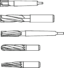
End mill with morse taper
End milling cutter with parallel shank
Right-hand direction of cut with right-hand helix
End milling cutter with morse taper
Right-hand direction of cut with left-hand helix
Die-sinking milling cutter with parallel shank
Right-hand direction of cut with right-hand helix
Conical die-sinking milling cutter
Right hand cutting with right hand helix
Fig. 9.27 End milling cutter
(e.g. in die construction) as well as forming grooves, pockets, slots and cavities of
all kinds and sizes.
End milling cutters have to be designed in many cases with a large degree of
slenderness (l/D > 5–10) depending on the application (e.g. milling deep engrav-
ings in dies and moulds). This causes on the one hand, depending on the contact
and engagement conditions, chatter vibrations during the process, which can lead
to increased wear via fracture, especially in the case of hard, brittle cutting tool
materials. Additionally, both chattering and bending of slender tools lead to dimen-
sional and shape inaccuracies in the components. Measures taken to avoid these
phenomena should be sought in an optimization of the tool and cutting part geome-
try, engagement conditions and milling strategy as well as of the cutting conditions
[Schr74, Köni80, Hann83, Köll86].
End mills correspond to shell end mills in their construction; for clamping, they
are equipped with a parallel shank (with side-clamping and/or fastening thread)
or with a taper shank (Morse taper or steep-angle taper; sometimes with fastening
thread).
A distinction is drawn between right-cutting and left-cutting tools as well as
between right-hand spiral, left-hand spiral and straight-toothed tools (Fig. 9.27). The
mill form can be designed cylindrically, conically or as a custom design depending
on the machining task. The front face of the tool is generally round or half-round;
in the case of tools capable of drilling the face cutting edges must reach as far as the
tool centre.
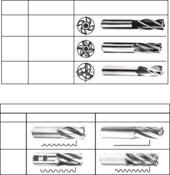
HSS end milling cutters are classified into tool applications groups in accordance
with DIN 1836 depending on the material to be machined (Fig. 9.28).
Profiling of the cutting edges in the case of roughing tools leads to a division of
the chips into smaller chips. The advantages of these chip dividers include improved
chip removal and cutting fluid access as well as reduced stress on the cutting edges
(Fig. 9.29).
The design of individual milling cutter geometries and chip divider forms differ
depending on the manufacturer.
In principle, all the cutting tool materials are potentially applicable in end
milling, depending on the selection criteria regarding workpiece materials and
9.2 Milling 403
Group of
application
Field of application
Machining of materials
with normal strength
and hardness
Machining of hard,
hard tough and/ or
short-chipping
materials
Machining of soft tough
and/ or long-chipping
materials
N
H
W
Tool
Fig. 9.28 Tool application groups
Rounded
profile
(R)
Flat profile
(F)
Profile Group N Group H
Profiled cuttting edges
Fig. 9.29 Cutting profiles of roughing-end milling cutters (Source: Fette)
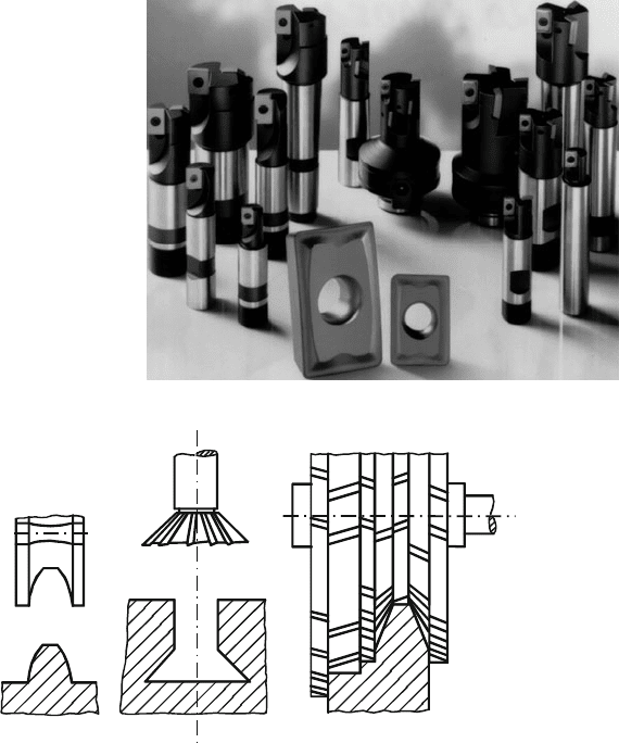
stability. High speed steel is still predominately used – often coated – as well as
cemented carbides. Besides solid steel tools, tools with soldered cutting edges and
clamped or bolted indexable inserts are used (Fig. 9.30).
A more flexible adjustment of the cutting tool material to the machining task
is possible by using tools with indexable inserts. Especially mentionable in this
context is the use of different cutting tool materials in a single tool. This can be
advantageous, for example, in the case of ball path milling cutters, which are subject
to highly diverse stresses along the cutting edges.
9.2.1.4 Profile Milling
Profile milling is milling with forming tools to produce profiled surfaces, e.g. for
milling grooves, radii, gear wheels and gear racks as well as guideways.
404 9 Processes with Rotational Primary Movement
Fig. 9.30 End milling cutter
with inserts (Source: Sandvik
Coromant)
Gang cutterForm cutter
Fig. 9.31 Profile milling cutter
Profile milling tools are adjusted to the form of the profile to be produced. In
most cases, a peripheral face milling process is the result. As shown in Fig. 9.31,
the tools are designed in one part (form milling cutters) or in multiple parts (gang
milling cutters).
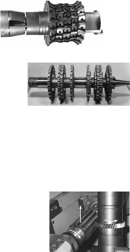
Profile milling cutters are in many cases manufactured as solid HSS tools due to
the favourable machinability and inexpensive price. Increasingly however, cemented
carbide indexable inserts or soldered cemented carbide cutting edges are being used
(Figs. 9.32 and 9.33).
9.2.1.5 Hobbing
In almost all areas of technology, gears are employed as components of an exact
and effective transmission of motion. For high-precision gears, the gears are
9.2 Milling 405
Fig. 9.32 Gang cutter for machining of grey iron profiles (Source: Walter)
Fig. 9.33 Gang cutter for
machining of machine beds
(Source: Walter)
manufactured primarily by machining. Because of its high efficiency, hobbing
is the dominant machining process for producing externally toothed cylindrical
gears.
In hobbing, the coupling of a worm with a worm gear is simulated, whereby a
worm interrupted by gashes represents the tool and the worm gear represents the
workpiece to be manufactured.
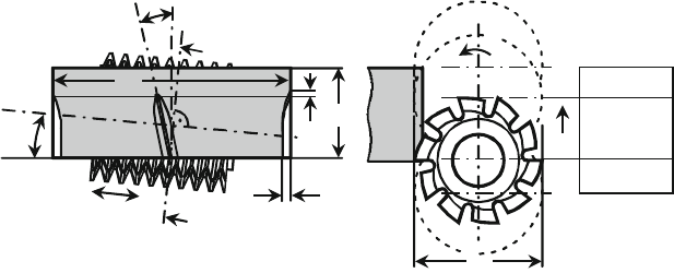
The kinematics of the process will be explained briefly with the help of Fig. 9.34.
The rotary movements of the hob and the gear serve to remove the chips. Depending
on the hobbing method, superimposed over these are translatory motions of the tool
in the axial and tangential directions as well as in the radial direction in order to
reach the depth of cutting. This results in the hobbing methods axial, radial-axial,
v
c
f
a
n
w
Fig. 9.34 Kinematics of
hobbing
406 9 Processes with Rotational Primary Movement
tangential, and diagonal hobbing. In industrial production, axial hobbing is currently
the most commonly employed process.
The feed in one direction is defined as the distance travelled per workpiece
rotation. We distinguish between climb and conventional cutting by means of the
direction of the axial feed f
a
. In climb cutting, the cutting speed and axial feed
motion are directed opposite relative to the workpiece. For wear-related reasons,
climb cutting is generally preferred, especially in dry hobbing. The traverse path of
the hob can be subdivided into the tool inlet and outlet phases as well as that of
full cut, where only in full cut does one obtain the theoretical maximum circular cut
lengths and material removal rates (Fig. 9.35).
There are two further process variants used to machine helical gearings, hobbing
in the s ame direction and in the opposite direction, whereby the pitches of the tool
and working gear are aligned in the same direction or in opposite directions.
In order to distribute the tool wear arising during the process evenly along the hob
for more a efficient use of the tool, the hob can be shifted along its axis in discrete
steps. This displacement takes place as a rule after each machined workpiece and is
also called “shifting”.
The parameters of a hob can be seen in Fig. 9.35, which shows the tool in the
machining sequence. The hob is a cylindrical screw interrupted by chip flutes which
bring about the gash. The number of worm threads on the cylinder determines the
thread number of the hob. The hob teeth are shaped so that tool orthogonal clear-
ances and the potential of regrinding the rake face without altering the tooth profile
are created. The pivoting angle or lead angle of the hob results from the direction
and size of the helix angle and the pitch angle of the hob worm.
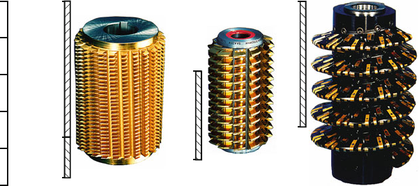
Hobs are classified into three different groups with reference to their construction
type (Fig. 9.36).
Solid steel hobs are manufactured from solid material, whereby the entire body
must be constructed from high-quality HSS or cemented carbide. Inserted blade hob
and cutters with indexable inserts on the other hand consist of a base body made of a
more inexpensive material. These hobs are especially suited to manufacturing gears
η = β
2
γ
0
f
a
β
2
d
a2
Shift
A
A
b
T
Section A-A
v
c
d
a0
Recess
Full cut
Entry
f
a
±
Fig. 9.35 Terms of the hobbing process
9.2 Milling 407
Full steel hob Inserted blade hob
Cutter with indexable
inserts
0
100
200
300
400
500
mm
Diameter d
a0
500
20
140
(HSS)
(HM) or
(HSS)
300
60
500
160
Fig. 9.36 Hob types (Source: Fette, Saacke, Saazor)
with large diameters and large modules. Besides the potential of realizing larger
constructive tool orthogonal clearances, the inserted blade hob also has a relatively
large potential usable tooth thickness (large number of regrinds). Fastening is done
with lateral clamp rings. In the case of cutters with indexable inserts, the tool cutting
edge, which is made of cemented carbide, is used upto four times and not reground.
This hob type is only suitable for workpieces beyond a modulus of 5 mm because
of the resulting poorer cutting quality.
With respect to the s election of the substrate/coating system, a sufficient amount
of substrate toughness is of especial importance in hobbing because of the inter-
rupted cut. At the same time, the tool must have as much wear resistance as possible
against abrasive and thermal wear mechanisms in conjunction with a suitable hard
material coating. By the establishment of (Ti,Al)N coatings is it possible to perform
dry machining processes at cutting speeds up to v
c
= 200 m/min, even with tool
systems based on HSS [Wink05].
More and more, coated gear tools are reconditioned. The coating is removed, the
tool reground and finally recoated on the rake face after the tool operating life is
reached [Klei03]. In this way, we can work with consistently high cutting speeds
in all tool cycles, and the tool’s operating life can be held constant. For reasons of
accuracy, ground cutters cannot be over-coated more than 5–10 times because of the
coating application on the already coated rake face.
Figure 9.37 clarifies the hobbing process by looking at the creation of a tooth gap.
Due to the process kinematics and the resulting shifting between the tool and work-
piece, the material of a tooth gap is machined in the successive engagements (hob-
bing positions) of the individual teeth of a hob thread as can be seen in the sketch
in the bottom left of the illustration. The evolvents on the tooth of the workpiece
are approximated by profiling cuts. Every cutting tooth makes a cut after one tool
rotation in a further tooth gap determined by the hob thread number, but in the same
hobbing position; i.e. it is always removed one chip with the same cross-section.
408 9 Processes with Rotational Primary Movement
Section A
Cross section of
undeformed chip
Generated
cut
B
Hob tooth
Section B
Generated cut deviation
Involute
Fig. 9.37 Ratio of engagement in the hobbing process
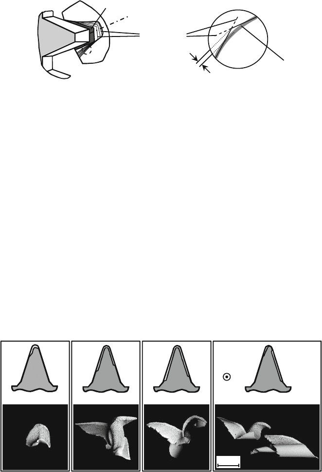
Due to the differing penetrations between the hob and the workpiece in the partic-
ular hobbing positions, variously thick and variously formed chips result (Fig. 9.38).
During the first tooth engagements, a large amount of the gap volume is machined,
so that here, especially shortly before the middle position, exist the largest cross-
sections of undeformed chips. In the following hobbing positions, the tooth gap
is mostly profiled and the cross-sections of undeformed chip are reduced. The
penetration areas are highlighted in the image.
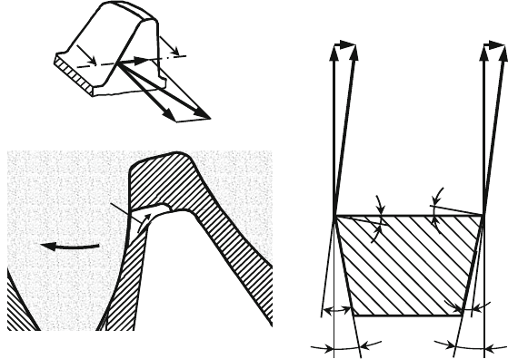
During hobbing, as in other gears manufacturing processes, changes to the struc-
turally given tool orthogonal clearance and tool orthogonal rake angles occur during
the cutting process [Sand72, Sulz73, Sulz74, Köni79]. Figure 9.39 illuminates the
cause of this.
At the cutting point under consideration on a certain hobbing position, the effec-
tive cutting speed v
r
results from the cutting speed of the hob v
c
and the hobbing
speed v
A
. On the entering tool cutting edge (Fig. 9.39), this leads to an enlargement
of the structurally given tool orthogonal clearance but simultaneously to a reduction
of the tool orthogonal rake angle. This means that, during the cutting process, the
Upper chip side
Direction of
primary motion
3mm
Rake
face
Hob profile
Hob profile
Hob profileHob profile
v
c
Fig. 9.38 Chip formation in the hobbing process
9.2 Milling 409
EF
α
kon
α
kon
γ
eff
γ
eff
α
eff
α
eff
v
A
v
A
v
A
v
c
v
c
v
c
v
c
v
r
v
r
v
r
AF
cut C-C
C
C
workpiece
n
w
Tool
Fig. 9.39 Relative velocity and effective cutting geometry
effective tool orthogonal clearance is larger on the entering face than the structurally
given one. The effective tool orthogonal rake angle, on the other hand, is smaller.
There are different ratios on the exiting face, upon which the effective tool orthogo-
nal clearance is small and the effective tool orthogonal rake angle is larger than the
corresponding structurally determined angles.
A penetration calculation can be applied to simulate the cutting process
[Wink05]. In the penetration calculation, the workpiece is analyzed into a certain
number of parallel planes. By recreating the axis motions of the hobbing machine,
the cutting path of the hob teeth are generated so that they cut the workpiece
planes. From the intersection we can calculate a penetration range that corresponds
to the chip geometry of the respective hobbing position in the process [Weck02,
Weck03].
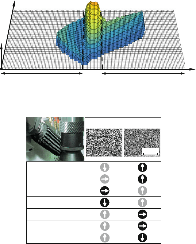
Figure 9.40 shows a simulated chip geometry in a certain hobbing position. The
3D chip diagram reproduces the distribution of cross-sections of undeformed chips
along the uncoiled cutting edge along the cutting arc, whereby the beginning of
the cut is in the foreground. The calculated chip geometries form the basic data
of a simulation-supported assessment of the stresses affecting the hob during the
machining process. It is clear that the chip thickness (top chip thickness) in the top
region of the hob can be much larger than in the edge region.
In addition to cemented carbides, PM-HSS cutting tool materials have also
become established as substrate materials for hobs in dry hobbing processes. Since
both cutting tool materials are in competition with one another, Fig. 9.41 shows the
advantages and disadvantages of both tool systems. The advantages are designated
with bright points, the disadvantages by dark points.
410 9 Processes with Rotational Primary Movement
Cutting edge handling
Length of the incoming flank
Length of the outbound flank
h
Cut-bend handling
Head
Fig. 9.40 Tension geometry in hobbing
Tool original price
Preparation charge
Wear resistance
Cutting speed
Chip thickness
Hardiness
Process reliability
HSS
HM
30 µm
Source: Samputensili
Fig. 9.41 Cutting tool materials for dry hobs
One of the main disadvantages of cemented carbide hobs in comparison to
the HSS variant is the higher cost of acquiring the tools. They are generally at
least three times more expensive. Because of the higher tool costs, it is only eco-
nomical to use them if a significantly higher productivity or longer tool life is
obtainable.
Because of the much higher wear resistance of cemented carbide, cemented car-
bide tools can realize clearly higher cutting speeds. However, PM-HSS hobs can
realize larger maximum head chip thicknesses. Given the high tool price, the use
