Klocke F. Manufacturing Processes 1: Cutting
Подождите немного. Документ загружается.

8.2 Process Monitoring 371
18.7 18.8 18.9
19
19.1
200
300
400
500
600
700
800
Temperature T /°C
Drilling distance/mm
0.1 mm = f
0.05 mm = ½ f
Temperature /°C
18.86 18.88 18.9 18.92 18.94
200
300
400
500
600
700
800
Drilling distance/mm
0.05 mm = ½ f
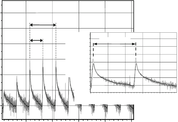
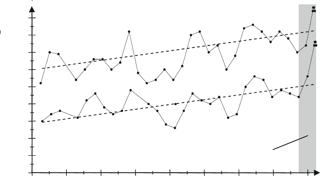
Fig. 8.32 Example of a highly detailed temperature signal
In the case of the system described here, the lower limit of measurable tempera-
ture is about 200
◦
C. The potential temperature resolution depends on the selection of
the amplification factor. A higher amplification factor results in a higher resolution
but also reduces the measurable temperature range and the measurable maximum
temperature. While losses of intensity by partial impurification of the optics do not
distort the measurement result, measurement errors do occur in the case of differing
emission degrees for both of the wavelengths on which the measurement is based.
When cutting fluids are used, measurements are extremely unstable due to the dif-
ferent optical properties of the cutting fluid and the fibre material if the optic is
wetted.
8.2.2 Signal Processing and Monitoring Strategies
In order to develop process monitoring strategies, signal processing is first required.
Independently of whether the signals are obtained from external sensors or by
machine tool control readouts, these signals should exhibit a close correlation to
the process.
Depending on the required system reaction speed, the methods used either
accompany the process or are intermittent. A continuous, process-concomitant
measurement offers the most rapid possibility of detecting events and introducing a
suitable reaction. The intermittent measurement permits reaction after reinstatement
372 8 Process Design and Process Monitoring
of the measurement cycle at the earliest, so it is possible that disturbances arising
outside the measurement cycle are not reflected in the measured signals.
No new information is generated during signal processing. Signal processing
has the exclusive function of extracting from the total received information that
information which relates to the process parameters to be monitored. A basic dis-
tinction is drawn between online and offline signal processing systems. In the case
of online processing, signal reception and signal processing occur simultaneously.
In offline processing, signal reception and processing are physically and temporally
separated.
The properties and characteristics of the systems used determine to quite a sig-
nificant extent the basic properties of the signals that are picked up. Therefore, it
is necessary to determine signal processing strategies with an eye to the signal
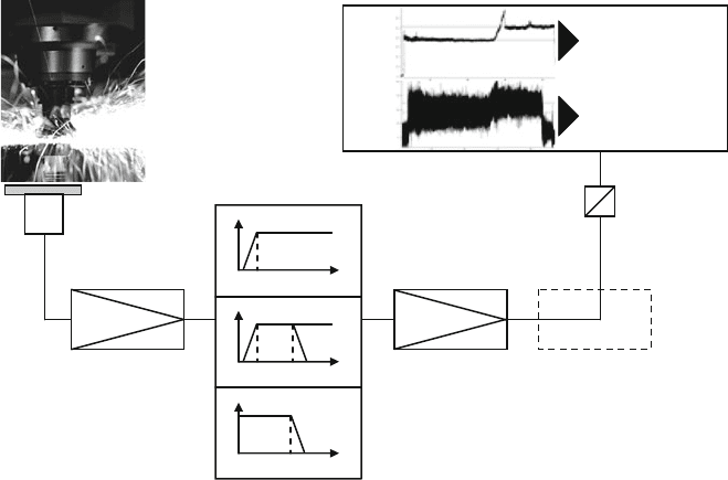
properties. Figure 8.33 shows an example of a measurement path for the acquisi-
tion of AE-signals in a machining process. This measurement path is characteristic
of many other manufacturing processes. The signals generated by the sensors
generally have low energy contents. The signal-to-noise ratio (SNR) is thus low,
making disturbance-free signal transmission and evaluation more difficult. In order
to improve the SNR therefore, the signal is subject to preamplification. Often the
signal data is then filtered in accordance with the frequency range that is relevant
for the given monitoring task. Depending on the monitoring task and the type of
sensor signals, either highpass, lowpass, or bandpass filtering takes place.
Process
Signal acquisition
and assessment
Pre-intensification
RMS-ractification
Sensor
/-s
A-D
converter
Reaction on
detected process
solutions
Documentation
of process
developments
P
1
P
2
Highpass
A
f
g
f
Bandpass
A
f
u
f
Lowpass
A
f
g
f
f
o
F
Z
M
Z
Main amplification
Fig. 8.33 Measurement path for acquisition of acoustic emission
8.2 Process Monitoring 373
The essential function of signal filtering is to filter out those signal components
from the raw signal that do not correlate with the process parameters to be moni-
tored. The irrelevant signal components might contain information assigned to the
process but which is not relevant for the application at hand, or they might be extra
disturbance signals that were introduced into the measurement chain from outside.
Examples of disturbances include irrelevant machine vibrations or external electro-
magnetic disturbance fields. After signal filtering, amplification takes place in the
main amplifier. Optionally, especially in the case of AE-signals, the effective value
of the sensor signals can be rectified following Eq. (8.55).
s
eff
=
1
T
T
0
s
2
(t)dt (8.55)
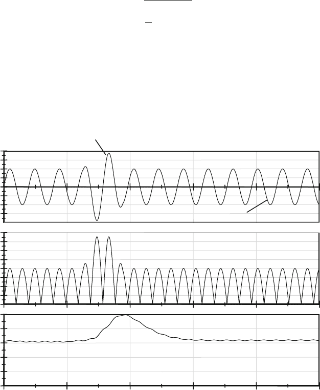
For the sake of simplicity, preprocessing is applied to a signal with constant fre-
quency (Fig. 8.34). In the effective value rectification, a time-dependent, sliding,
quadratic average – the RMS (root-mean-square) – is formed from an output signal
[Saxl97, Reub00].
0
0
0
Time t
Voltage U
Voltage U
Voltage U
Lowpass filtered signal
Bandpass filtered signal
Rectified signal
Continuous signal fraction
Burst fraction
Fig. 8.34 Filtering and RMS-rectification
374 8 Process Design and Process Monitoring
RMS signals have only positive signal components and are used to determine
monitoring parameters. After the effective value is rectified, further filtering or
amplifying of the signals may be necessary depending on the case at hand. In
order to make information-technological processing of the signals possible, the ana-
logue measurement values are digitalized in an analogue/digital (A/D) converter.
The measurement values can then be acquired, evaluated with the help of software
and further processed in digital form.
Principally, it is possible to consider signals in the time range or frequency range.
Wave analysis makes it possible to combine information coming from both r anges.
Table 8.3 compares general attributes of the three methods [Reub00].
In the case of time-consuming monitoring processes, signal evaluation in the time
range has the advantage that it does not require a time-consuming transformation
into the frequency range that demands a large amount of computer capacity. In the
simplest case, process disturbances lead to significant signal changes that can be
determined directly from the temporal signal profile.
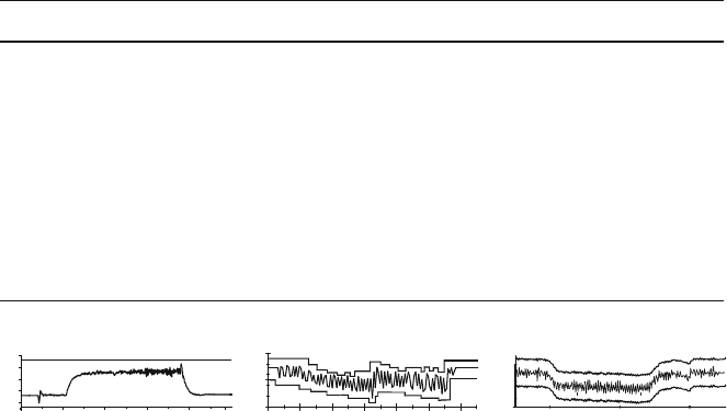
Action limits and tolerance zones are useful for identifying disturbances.
Figure 8.35 shows some classic examples. Besides a static limit value, a trend, a
tolerance zone and revolving thresholds, it is also possible to identify characteristic
signal profiles.
Monitoring by means of static thresholds is the simplest type of signal-based
monitoring. The signal level for the undisturbed process profile is determined in
preliminary tests. This signal level is then used for monitoring in the form of a
stable limit. In the case of monitoring with dynamic thresholds, a sliding average
is calculated from the recorded signal over a defined time period. This average is
Table 8.3 Characteristics of signal analysis in the time and frequency ranges
Time range Frequency range
Temporal signal profile Transformation of the signal into the
frequency range
Continuous signal analysis or in temporally
limited sections
Spectral signal composition
Almost no information regarding signal
frequencies
Discontinuous signal evaluation in temporally
limited signal sections
No time-consuming transformation No information regarding temporal signal
changes in the transformed signal section
Limited information regarding the temporal
signal profile by analysis of several
consecutive signal sections
Static thresholds
Stable limits
Time
Signal
Tolerance zones
Time
Signal
Time
Signal
Fig. 8.35 Action limits and tolerance zones
8.2 Process Monitoring 375
associated with a percentage addition or deduction, making it possible to monitor
the signal profile dynamically. The advantage of this strategy compared with a stable
limit is that it is also possible to monitor signals that do not proceed uniformly or
whose level constantly changes even in an undisturbed process.
Saxler provides an example of signal analysis in the time range in his disserta-
tion on the structure of a system for recognizing grinding burn via acoustic emission
analysis [Saxl97]. Grinding burn is a form of undesirable thermal rim zone damage
and is described more thoroughly in volume 2 of this series. When profile grind-
ing tooth flanks, a structure-borne sound sensor is affixed near the workpiece. The
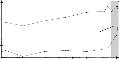
profiles of the RMS values of the signals are shown in Fig. 8.36 for the roughing
and finishing phases of the machining of a total of 1650 gearwheels. Of particular
interest is that both graphs have asynchronous profiles until the 900th gearwheel.
Beyond that point, the graphs are almost parallel and differ by a signal difference of
about 1 V. After reaching the end of tool life (i.e. after grinding 1550 gearwheels)
are found the highest RMS values of the acoustic emission within the tool life with
the exception of the first two evaluation points.
Irrespective of the fact that the appearance of grinding burn at the first two evalua-
tion points can not be detected by exceeding the threshold value, the total amplitude
differences are not large enough to lead to reliable information about the develop-
ment of grinding burn. This practical example will be taken up again when dealing
with signal analysis in the frequency range.
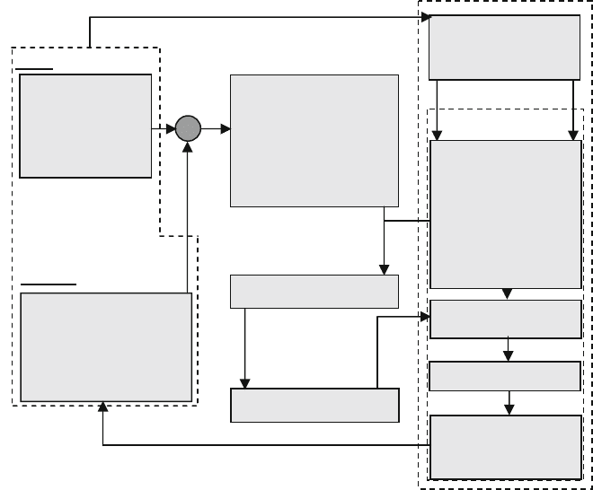
Besides the pure detection of deviations, breach of the action limits can be used
to produce an automatic reaction of the machine by altering the process parameters
(Fig. 8.37).
0 200 400 600 800 1000 1200 1400 1600
2
2.5
3
3.5
4
4.5
5
5.5
6
6.5
Finishing
Grinding burn
Amount of gearwheels/pcs.
Averaged AE-RMS
Roughing
U
RMS
/ V
Fig. 8.36 Analysis of acoustic emission in time interval
376 8 Process Design and Process Monitoring
Process
Machine
External sensors
Force
Path
Speed
Acceleration
Effective-power
Temperature
External control
Drives
Actuators
Material
Workpiece
Geometry
Machine
Clamping
Feed
Cutting speed
Cutting strategy
(Cutting depth)
(Tool geometry)
Definition of interfaces
Coupling module
Internal signals
Revision
Storage
NC-kernel
Control algorithm
Drives
Actuators
Sensors
Variable parameters
Fixed parameters
Path
Speed
Acceleration
RPM
Power
Cutting fluid
pressure
Fig. 8.37 Concept for intervention in the manufacturing process
For this purpose, there are two basic control strategies, adaptive control constraint
[Gies73, Häns74, Müll76, Gath77] and adaptive control optimization [Esse72,
Otto76]. In the case of adaptive control constraint (ACC), the variable of the con-
trol loop is varied such that the control variable reaches a level that is as constant
as possible. One classic example of an adaptive control constraint in machining is
the maintenance of a constant level of torque by adjusting the feed in the case of
an alternating overmeasure. Adaptive control optimization involves varying one or
more variables so that the control variable follows a learning curve. The learning
curve could represent, for example, the profile of spindle performance over the feed
path and be stored for a specific machining situation as an optimal process sequence.
The parameters feed and speed could then be freely selected within defined limits
so that the performance follows the learning curve despite wear.
New developments in process monitoring are focused on model-based monitor-
ing methods or simultaneous evaluation of different sensor signals in order to obtain
a maximum amount of security from interruption. This is necessary because fre-
quent false alarms are a major problem in the industrial use of process monitoring
systems in the case of the devices used today. For adaptive control constraint and
8.2 Process Monitoring 377
adaptive control optimization, often control algorithms are therefore implemented
that combine and evaluate one or more pieces of sensor information. The output of
the system can be characterized by several variables.
Signal evaluation in the frequency range is especially sensible when different
periodic signal components are superpositioned. This is often the case in machining
operations since dominant process frequencies such as turning or tooth engagement
frequencies as well as their overtones are superpositioned by the characteristic fre-
quencies of the machine and tool. From the representation of amplitude performance
spectra over frequency, information can be obtained regarding the appearance of
signal components at different frequencies and across frequency shifts. Often, fre-
quency analysis also makes it possible to identify process disturbances, for example
the appearance of chatter vibrations or significant changes on selected cutting edges
in milling operations. Process disturbances of this kind are easier to detect in the
frequency range than in the analysis of process signals in the time range.
The most well-known method of frequency analysis is based on the F
OURIER
transformation. The method most used in industrial practice today is the fast Fourier
transformation (FFT), which is characterized by its fast and efficient transformation
algorithm.
Generally, when analyzing process information in the frequency range, one must
bear in mind that the time information of when a certain signal event occurs is lost.
For this reason, often analyses in the time and frequency ranges are combined. This
will be dealt with later (wavelet analysis).
Saxler’s system for recognizing grinding burn via acoustic emission analysis
again provides a practical example for signal analysis in the frequency range.
Roughing and finishing signals during tooth flank profile grinding undergo an FFT
within a frequency range of 200–400 kHz. Throughout the tool life of the grinding
wheel, the profiles show an increase of about 1 dBV in the averaged acoustic emis-
sion amplitude. Analysis of the measurement data gathered from the finishing phase
demonstrates a clear relation between the averaged acoustic emission amplitudes
and the appearance of grinding burn (Fig. 8.38).
0 200 400 600 800 1000 1200 1400 1600
–52
–51
–50
–49
–48
Grinding Burn
Finishing
Roughing
Amount of gearwheels/pcs.
Averaged AE-Amplitude U /dBV
-
-
Fig. 8.38 Analysis of acoustic emission in frequency range
378 8 Process Design and Process Monitoring
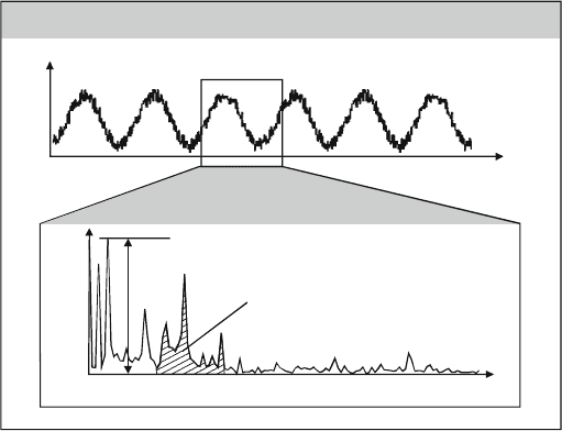
Both in the time range and in the frequency range, it is possible to form sig-
nificant signal characteristic values and to set t hem in relation with each other. The
characteristic values are calculated either from very narrow frequency bands or from
the amplitude spectrum in one relevant frequency band. In the first case, the values
of the amplitude peaks are usually directly drawn upon for evaluation, in the sec-
ond often integrating characteristic values are ascertained from the profile of the
amplitude spectrum that correlate with the energy content of the signal. Figure 8.39
compares example signals from the time and frequency ranges and illustrates the
corresponding characteristic values [Reub00].
The Fourier transformation’s usefulness is limited in the case of time-critical
signal analyses and highly dynamic processes. One weak point is in the delayed
preparation of the evaluation r esult because information about included signal
characteristics can only be made after complete transformation of the signal sec-
tion. The maximum delay results in case a disturbance-related signal characteristic
appears at the beginning of the signal section under consideration and is only rec-
ognized after the end of that section. No information about the time or temporal
sequence of the appearance of the frequencies contained in the signal exist within
the analyzed signal section.
One possibility of increasing the time resolution consists in selecting the width
of the signal section so narrow that every signal segment can be considered as quasi-
stationary and then to consider the sequential progression of several successive
signal sections. This is the functional principle of the short-time F
OURIER analysis
(STFT). In comparison with FFT, short-term changes in amplitude are not as level.
The result for the shortened signal section is represented analogously to FFT. The
faster the relevant signal changes arise and the shorter the permissible delay time
for their recognition, the smaller the signal sections should be selected. However, a
Frequency-transformation
Frequency f
Amplitude A
max
peak
Amplitude A
Time t
max
peak
Maximum of amplitude
Characteristics from the amplitude spectrum
A
FB
A
FB
Integral of amplitude
spectrum in a
frequency band
Fig. 8.39 Transformation from time into frequency range and characteristic values
8.2 Process Monitoring 379
wide signal section is necessary for a high frequency resolution capacity in order to
obtain information about the low-frequency signal components that is as complete
as possible. One approach to solving this goal conflict is raising the sample rate
when digitalizing the signal. This makes a larger amount of discrete values avail-
able for the transformation, but requires a larger amount of computing time and
memory requirements.
Wavelet analysis is the logical development of the notion of analyzing a signal in
real time and completely in its contained frequencies. Different frequency ranges of
a signal can be investigated with different temporal resolution. While in the case of
the F
OURIER transformation only a constant signal section can be selected for the
entire frequency range of the signal, the wavelet algorithm adjusts the size of the
section to the respective frequency band under consideration. So in the case of high-
frequency signal components, there is a very good temporal resolution and at low
frequencies very good spectral resolution. Another advantage is that the transformed
signal can be fully reconstructed by means of an inverse wavelet transformation.
We differentiate between continuous wavelet transformation (CWT) and discrete
wavelet transformation (DWT). In CWT, the output signal is multiplied by a wavelet
function. The wavelet function ψ has a constant number of vibrations and is thus a
wave packet. It has a shifting parameter τ and a scaling parameter s (Eq. (8.56)).
ψ
τ ,s
=
1
√
s
ψ
t − τ
s
(8.56)
The shifting parameter contains the time information in the transformation range,
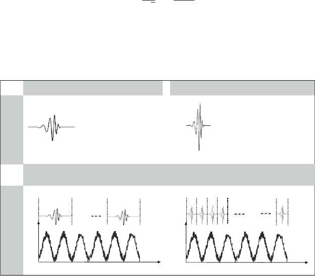
while the variation of the scaling parameter correlates with the frequence-related
evaluation (Fig. 8.40).
Stretched wavelet function Forged wavelet function
Scaling
parameters
Shifting
parameter t
Time
Amplitude
...
Time
Amplitude
...
t
j
Acquisition of temporally signal changes by shifting the wavelet function
Big scaling para-
meter s
i
(e.g. s
i
=
1)
for slow signal-
changes and low
frequencies
Small scaling parameters s
i
(e.g. s
i
= 0.25) for high
frequency signal fractions
Fig. 8.40 Shifting and scaling of the wavelet function

380 8 Process Design and Process Monitoring
The signal is temporally resolved by shifting the wave packet along the time
axis, as the shifting parameter contains the current location along the time axis. By
varying the scaling parameter, the wave packet is expanded or compressed so that
its length becomes a measure for the analyzed frequency range.
In accordance with the principle of multiple solutions, the temporal signal pro-
file is transformed several times while varying both parameters. The product of the
respective signal section x(t) with the wave packet creates a function whose integral
corresponds with the wavelet coefficient c (Eq. (8.57)).
c
(
τ , s
)
=
1
√
|
s
|
x
(
t
)
ψ
t − τ
s
dt (8.57)
The calculated coefficient is a measure for the similarity between the analyzed
signal section and the shifted or scaled wave packet. Pattern recognition is an impor-
tant strength of the algorithm. In order to exploit this property, it is necessary to
adjust the wave packet to the current signal characteristics by selecting a suitable
basic form.
For practical applications in signal transmission, often the discrete wavelet trans-
formation (DWT) is used since they require less computing time and provide
extensive possibilities in signal profile evaluation and presentation. The key differ-
ence between CWT and DWT is that in the case of discrete wavelet transformations
the signal is broken down into individual frequency ranges by repeated highpass and
lowpass filtering. The individual layers of analysis are called decomposition layers.
Only the highpass-filtered signal components are coded with wavelet coefficients.
The output signal of the lowpass filtering is prepared for the next evaluation level
(Fig. 8.41)[Reub00]. “Downsampling” compresses the signal by purging the num-
ber of discrete individual signal values of information represented in the wavelet
coefficient (making it redundant) after highpass/lowpass filtering.
In the case of DWT, a wavelet coefficient represents, simply considered, the dif-
ference of two individual signal values. In every decomposition level, a vector of
wavelet coefficients is thereby formed which has half as many inputs as the decom-
posed signal. It represents exactly that signal information that is contained in the
frequency band resulting from highpass filtering of the respective decomposition
level and can thus be assigned to a certain frequency band. The signal vector result-
ing from lowpass filtering forms the basis for the next evaluation level. It is thereby
reduced by half of the individual signal values, which is possible, in agreement with
the Shannon sampling theorem, for the half-band frequency range considered in the
next evaluation level without loss of information.
The advantage of this procedure is that the amount of individual signal values
used in every transformation level for t he computation algorithm is adjusted to
the decomposed frequency band. While transformation into the frequency range is
bound to a constant number of signal values as a function of the spectral resolution,
in the case of “downsampling” during wavelet transformation the number of dis-
crete signal values in each processing level is clearly reduced. This saves not only
