Klocke F. Manufacturing Processes 1: Cutting
Подождите немного. Документ загружается.


8.2 Process Monitoring 361
Fig. 8.18 Dynamometer
for drilling processes
(Source: Kistler)
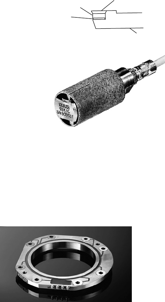
Similar systems exist for turning and milling processes as well. Figure 8.19
shows a rotating four-component dynamometer for milling.
Piezoelectric measuring systems are characterized by their high levels of stiff-
ness. If beyond this the oscillating mass located in front of the sensor element is
small, the measurement section has a high characteristic frequency. In this way it
is possible to analyze reliably dynamic process parameters even in high-frequency
areas. In common usage, this is often designated as the capacity of piezoelec-
tric measuring systems for highly dynamic measurement. Figure 8.20 shows the
schematic of tool holder for turning, in which a small piezoelectric force sensor for
measuring cutting force has been fit beneath the cutting edge.
This principle can also be applied to rotating tools. In this case, a signal transmis-
sion between the rotating and stationary parts of the measuring system is required.
Such systems are currently still in prototype stage.
If however high dynamics are unnecessary in the measurement, measuring in the
secondary force connection has as a rule the advantage of simpler sensor integration
into the machine’s structure. Besides strain gauges, above all piezoelectric force
Fig. 8.19 Rotating
dynamometer for milling
processes (Source: Kistler)
362 8 Process Design and Process Monitoring
Insert
Slim-line-
sensor
Intermediate element
Insert holder
Fig. 8.20 Turning tool with
integrated dynamometer
Fig. 8.21 Quartz transverse
measuring pin
(Source: Kistler)
measurement pins are suitable as sensors in such cases (Fig. 8.21). These indirectly
measure force via the strain of the structure into which they are integrated.
A general disadvantage of measuring in the secondary force connection is that
it is necessary to analyze the machine structure in order to determine the optimal
assembly location. If this is chosen correctly, it is then possible to monitor tool
fracture and overload.
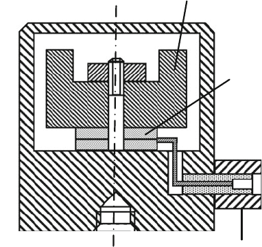
Force measurement rings – integrated into the main or feed spindle bearings
of drilling, turning and milling machines – are another possible way to measure
resultant force. Figure 8.22 shows a piezoelectric ring sensor. In some cases, it is
also possible to apply s train gauges on the outer bearing ring or in a special bearing
sleeve.
Fig. 8.22 Multicomponent force sensor for integration into spindle bearings (Source: Kistler)
8.2 Process Monitoring 363
8.2.1.4 Accelerometers
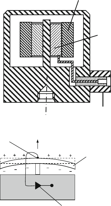
For measuring mechanical process dynamics in machining, usually piezoelectric
accelerometers are used. The basic functional principle is based on the propor-
tionate relation between force and acceleration. The factor of proportionality is
the inert mass of the body upon which the force is acting. The main components
of an accelerometer are therefore the seismic mass, sensor element and housing
(Fig. 8.23).
In detail, we differentiate between three different accelerometer designs, in which
a charge transfer is produced by normal forces, shear forces or flexural forces. A sen-
sor element acting on normal forces is shown in Fig. 8.24. As a result of the design,
the large surface contact between the sensor element and the base plate leads to
the stresses of the measured object being transferred via the base plate to the sen-
sor element. This brings about a measurement error. Furthermore, the pre-stressing
is altered by temperature changes, so that thermally caused errors in measurement
can also occur. The susceptibility of the sensor type to these sources of disturbance
is much lower in the case of shear-sensitive accelerometers (Fig. 8.24). Besides
their lower basic strain sensitivity, shear-sensitive piezoelectric ceramics exhibit no
thermally caused charge transfer (pyroelectricity).
Every mass additionally mounted on the measured object changes its vibrational
properties (characteristic frequency) and thus in certain conditions call into question
the result of a measurement. It is especially important to take this fact into consid-
eration in the case of experimental modal analysis. The mass of the accelerometer
must be much smaller than that of the structural mass to be analyzed. One example
Seismic mass
Sensor element
Connector
Fig. 8.23 Schematic assembly of an accelerometer
364 8 Process Design and Process Monitoring
Seismic mass
Sensor element
Connector
Fig. 8.24 Accelerometer
with shear sensitive sensor
element
Charge amplifier
Tap
a
Piezoelectric ceramic
beam
Fig. 8.25 Accelerometer
with a piezoelectric beam
of a mass-reduced accelerometer is shown in Fig. 8.25. The active component of
the accelerometer consists here of a piezo-ceramic bending beam. Upon displace-
ment of the beam due to acceleration, a charge transfer is caused. In this case, the
sensor element and the seismic mass are identical. Besides the low characteristic fre-
quency and the pyroelectric attributes of the sensor, improper use results in marked
sensitivity to mechanical destruction due to beam fracture.
The sensor is selected primarily in accordance with the measurement range,
sensitivity, the mass and characteristic frequency. Simultaneous fulfilment of all
goals represents an optimization problem due to physical limitations. For exam-
ple, increasing sensitivity over a larger seismic mass results in a lower characteristic
frequency and thus to a more limited available frequency range. This can been seen
in Eq. (8.53), in which f
0
is the characteristic frequency, c the stiffness of the sensor
element and m the seismic mass.
8.2 Process Monitoring 365
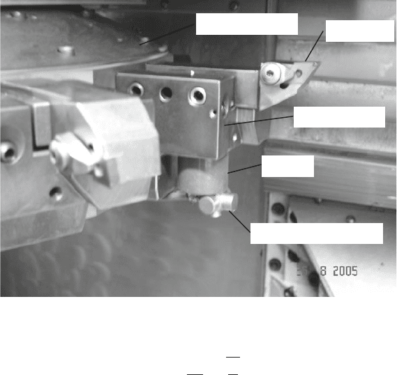
Tool
Tool turret
Tool holder
Magnet
Accelerometer
Fig. 8.26 Application of an accelerometer at the tool holder
f
0
=
1
2π
·
c
m
(8.53)
In comparison to quartz, some piezoelectric ceramics provide charge differences
that are 100 times higher under otherwise identical conditions. This property can
be utilized in order to reduce the seismic mass by a factor of 100 at equal sensor
sensitivity. However, ceramic elements are generally not as stiff, so this approach
leads to losses with respect to the characteristic frequency.
In order to capture the dynamics of manufacturing process as freely as possible
of disturbances in practice, a triaxially measuring accelerometer should be applied
close to the action point, e.g. directly under the turning tool. This ideal solution is
not always realizable within the machining space of a machine tool. In Fig. 8.26,
the sensor was thus fastened with a magnet on the tool holder.
8.2.1.5 Acoustic Emission Sensors
There are also dynamics in the province of acoustic emissions [Eise88]. Depending
on the type and magnitude of the emission source, the frequency range extends from
audible sound (ca. 16 kHz) to the high ultrasound range (ca. 30 MHz). Figure 8.27
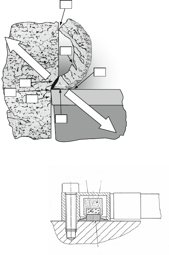
shows a diagram of possible sources and causes of the development of acoustic
emission (AE) in machining processes.
Figure 8.28 shows an AE-sensor in cross-section. The surface waves arrive via
a thin membrane with integrated docking element at the sensor element, which is
surrounded by a damping mass. No additional seismic mass is required to detect
366 8 Process Design and Process Monitoring
1 Plastic deformation
in the shear plane
2 Friction at the rake face
3 Crack initiation and crack
growth
4 Friction between tool and
workpiece
5 Collision of the chip on the tool
or workpiece
6 Chip breakage
7 Friction by redirecting the
chip on the rake face
Sound propagation
Sound propagation
1
2
3
4
5
6
7
Fig. 8.27 Sources of acoustic emission
Piezoelectric element
Damping mass
Membrane and docking element
Fig. 8.28 Schematic assembly of an AE-sensor
the AE signal. The inertia of the sensor element itself is sufficient to produce a
measurable charge transfer at typical frequencies between 50 kHz and 2 MHz.
Piezoelectric ceramics are especially suited to AE-measurement because of their
high sensitivity. AE-sensors are constructed such that the mechanical oscillation
direction is either perpendicular or parallel to the electric polarisation. In practice
however, still other piezoelectric or elastic coupling possibilities exist that can lead
to undesired resonances during the vibration measurement [Saxl97]. Thus, the area

8.2 Process Monitoring 367
of use of sensors is limited to suitable frequency ranges. Typical frequency ranges
are, for example, 50–400 kHz or 100–900 kHz.
Surface sensors are attached to the machine structure and register the surface
waves produced by the AE-signals. It is important that the optimal position for
sensor assembly is determined. Sensor selection and positioning are decisive crite-
ria for a successful process monitoring. AE-signals are attenuated at joining points
and material inhomogeneities in an order of about 11 dB per point of intersection
[Dorn93, Kett96]. The extent of this signal attenuation is also strongly dependent
on frequency. High-frequency signal components are more strongly attenuated than
low-frequency ones. When applying AE-sensors therefore, one is faced with the
basic conflict of goals between attachment near the process in order to receive sig-
nals that are as little attenuated as possible and a positioning which protects the
sensor from interference from hot chips or cutting fluid and does not obstruct tool
or workpiece change. In order to guarantee constant and reproducible coupling con-
ditions, the surface making contact with the sensor element must be machined to a
high level of surface quality.
Fluid acoustic sensors measure the AE-signal via a fluid jet (e.g. cutting fluid),
which is directed either at the workpiece, the tool holder or the tool.
With AE-sensors, fracture and wear can be recognized in turning as well as
in milling and drilling operations [Diei87, Dorn89, Kett96, Köni89b, Köni92b,
Mori80, Reub00]. Another area of application is in the recognition of unfavourable
chip forms in automated turning processes [Kutz91, Köni96, Kloc05a]. One exam-
ple from the sphere of grinding operations (see Manufacturing Processes, Volume 2)
is the recognition of burn by means of acoustic emission analysis [Saxl97].
Monitoring solutions based on acoustic emission are suitable for finishing processes
as well, since the use of other sensor principles has remained problematic due to the
small cross-sections of undeformed chip and low resultant forces.
8.2.1.6 Effective-Power Sensors
Changes to the resultant force components lead not only to dislocations or defor-
mations but also to a change in current and power consumption of the main and
feed drives. The power consumed by the motor of a machine tool is composed of an
effective and an idle component. Because of its proportionality to the torque emitted
by the motor, the effective power is often used as a signal within the control system
for quantifying the motor load. When monitoring cutting processes, usually exter-
nal effective-power measurement tools are used, often with associated evaluation
software and visualization unit.
The principle of effective-power measurement is based on determining the volt-
age U, current I and phase shift φ between both quantities. The effective power
is obtained from these using Eq. (8.54). We make a distinction between one, two
and three-phase systems, whereby three-phase systems have the highest resolution
because they execute the measurement in all three phases.
P
w
=
√
3 · U · I · cosφ (8.54)
368 8 Process Design and Process Monitoring
Effective-power
measurement-
transducer
Frequency
converter
I1
I2
I3
L1
L2
L3
3~
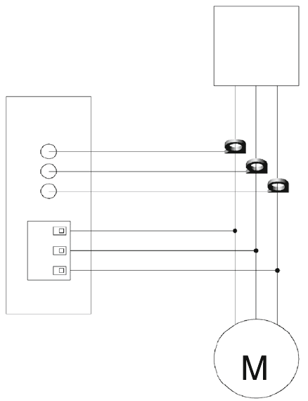
Fig. 8.29 Wiring diagram
for the assembly of
effective-power measurement
system
External effective-power modules are installed in machine tools between the fre-
quency converter and the motor. Figure 8.29 shows a typical wiring diagram for a
three-phase system. To read the current, hall s ensors are used that measure t he cur-
rent along with its phasing via the magnetic field surrounding the conductor in a
circular shape. During integration into the machine tool, signal adaptation is very
simple. Hall sensors are offered in various performance classes. The initial adapta-
tion can be achieved by varying the number of conductor loops that are led through
the hall sensors. Current systems also have electronic signal conditioners.
Effect-power measurement systems are characterized above all by the fact that
they do not affect the mechanical properties of the machine tool. The machining
torque can be measured during the operation without the integration of external
sensors into the electric flux of the machine. The primary area of application is the
recognition of tool fractures and collisions in the workspace. Sufficiently large force
changes are necessary for efficient wear monitoring. Furthermore, the systems are
inexpensive and easily retrofittable. Their suitability as an efficient process moni-
toring tool depends to a decisive extent on the ratio of the power input generated
by the machining process and the total power of the drive. Small machining torques
can thus no longer be reliably measured in the case of spindles with a collectively
large power input. Reliable monitoring is particularly difficult i n the case of small
8.2 Process Monitoring 369
cross-sections of undeformed chip or small process forces and torques, e.g. in the
case of finishing or of drilling with small diameters. The method is hardly suit-
able for measuring dynamic machining torques due to the high inertia (of the motor
armature, clamping mechanism and so on) in front of the sensors. The inert masses
of the power train represent a low-pass filter that considerably impedes the swift
measurement of dynamic magnitudes because of the low cutoff frequency.
8.2.1.7 Temperature Sensors
The cutting temperature is an important process-characteristic quantity for evaluat-
ing thermal stress on the workpiece and cutting tool material surfaces in the contact
zone. In addition to thermoelements, resistance thermometers and thermocameras,
quotient pyrometers are also used for measurement purposes, which provide highly
dynamic, precise and absolute information on temperature.
Thermoelements make use of the thermoelectrical effect between two metals.
Besides the single-cutter system and the twin-cutter system [Gott25, Vier70], it is
also possible to integrate a thermoelement into the tool [Küst54] or the workpiece
[Hopp03].
Resistance thermometers utilize the temperature-dependence of the resistance of
a conductor/semiconductor for temperature measurement. Usually metallic materi-
als are used, particularly platinum and nickel, the resistance of which increase with
temperature in an easily reproducible manner. Some semiconductors have negative
temperature coefficients, i.e. their resistance decreases with increasing temperature.
Thermocameras allow for a non-contact, extensive measurement of temperature.
They function according to the principle of thermography. Every object emits a
band of infrared radiation, the intensity of which is a function of temperature. The
wavelength range is between 0.7 and 1000 μm. The majority of commercial infrared
cameras use however only the spectral range of medium and long-wave infrared
from 3.5 to 14 μm.
In the case of a quotient pyrometer – also referred to as a ratio pyrometer or
2-colour pyrometer – intensity is not only measured with one wavelength but by
the ratio of the intensities of two different wavelengths. Infrared radiation is cap-
tured fibre-optically and sent to an evaluation unit. The glass fibre is s heathed with a
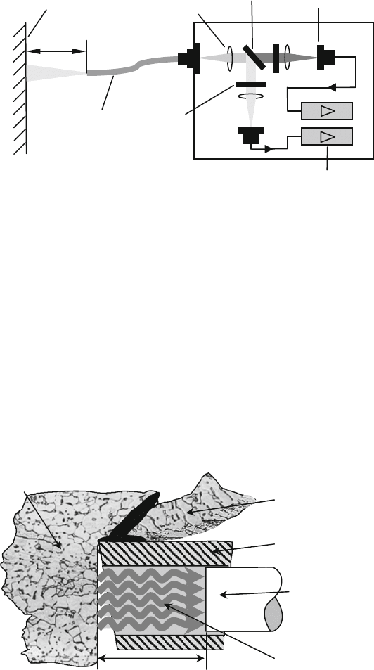
protective tubing. In the pyrometer housing are the optics, filter, detectors and a mea-
suring amplifier (Fig. 8.30). The principle of the quotient pyrometer is extensively
discussed in the dissertation of Müller [Müll04].
The electronic housing contains the control of the Peltier element cooling and the
power supply. Data acquisition and evaluation can be automatically executed with
an attached laptop.
Variations in intensity that are not caused by temperature, but rather, for example,
by partial impurification of the optics, have no influence on the measurement result.
Furthermore, measurement by quotient formation is for almost completely indepen-
dent of the degree of emission of the material so long as there is no significant
dependence on wavelength.
370 8 Process Design and Process Monitoring
Surface of the
measured
object
Light duct
Lens
Colour
divisor
Light sensor
Measuring
amplifier
IR-filter
L
Fig. 8.30 Functional principle of a quotient pyrometer (Source: WSA RWTH Aachen)
Metallically sheer surfaces have small degrees of emission. In order to measure
at optically difficult to access and thermally/mechanically heavily stressed areas, it
is possible to position a fibre-optic cable very close to the contact zone between
the tool and the workpiece. To do this, the measurement location must as a rule be
prepared with a hole, into which the fibre can be inserted. Figure 8.31 shows a typ-
ical application on an indexable insert for measuring temperature on the machined
surface of the workpiece.
Measurement data acquisition and evaluation can be carried out with a PC. The
result of the measurement is a temporally and spatially high-resolution temperature
signal such as is shown in Fig. 8.32 using an example f rom drilling.
Chip
Carbide tipped cutters
Quartz fibre of the
2-colour-pyrometer
(D = 0.42 mm)
Radiation
Workpiece
≈ 1 mm
Fig. 8.31 Temperature measurement of machined workpiece surface
