Klocke F. Manufacturing Processes 1: Cutting
Подождите немного. Документ загружается.

7.7 Machinability of Non-metals 331
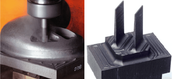
Fig. 7.52 Examples of sinking electrodes for electro discharge machining
a computer mouse (Fig. 7.52, left) usually complex free-form geometries must be
generated. Frequently, divided electrodes must be produced which are required for
the fabrication of grooves in injection moulding tools.
7.7.2 Fibre-Reinforced Plastics
Fibre-reinforced plastics (FRP) consist of a duro-plastic or thermoplastic polymer
matrix into which short or long fibres are embedded. Long fibres can be introduced
as roving or a sheet material. To produce components made of fibre-reinforced
plastics, as a rule post-production operations are required in order to form the
components in accordance with their function and geometrical characteristics. As
opposed to metallic materials, with which the component is often fabricated “from
solid”, it is attempted to fabricate components made of FRP close to the final contour
so that the ratio of the volume machined to the total volume remains small.
Fibre-reinforced plastic press parts can be deburred both by methods with geo-
metrically defined and geometrically undefined cutting edges. Since this volume
of the compendium deals exclusively with machining methods with geometrically
defined cutting edges, these methods will be in the foreground. Of this subgroup
of manufacturing processes, milling and sawing have proven the most effective. If
functional surfaces must be manufactured from plastic, high demands with respect
to formal and dimensional accuracy or high levels of surface quality cannot be
met, or at least only at unwarrantable cost. For example, only grinding methods
are used as the typical finishing method for producing clearances such as bearing
seats [Wuer00, Köni90b, Wien87, Wuns88].
To machine a component made of fibre-reinforced plastic, the mechanical and
thermal material properties are of especial importance. These are affected during
machining essentially by the properties of the fibre type used in the plastic.
This has a decisive influence on method selection or also, for example, the suit-
ability of tool designs. The fibre is characterized by high tensile strength, its elastic
332 7 Tool Life Behaviour
modulus and this low fracture strain compared to the matrix. In addition, it has,
depending on the fibre type, highly varied thermal parameters, which sometimes
deviate a great deal from those of the plastic matrix. However, reinforcement fibres
have differing properties under mechanical strain in accordance with their respec-
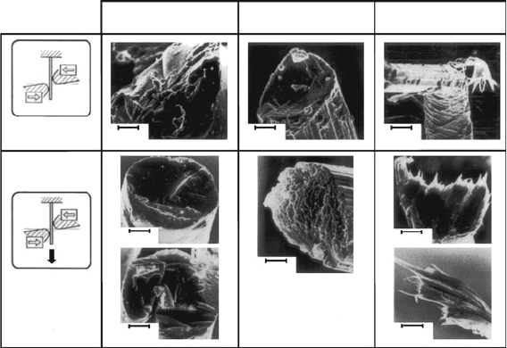
tive structure. Figure 7.53 clarifies this by looking at the fracture behaviour of single
fibres in different load cases.
Certain conclusions can be drawn from the results of the shear experiments, with
or without axial prestressing, regarding the “machinability” of the respective fibre
types. Glass and carbon fibres exhibit brittle fracture properties under tensile, shear
or bending strain, whereby the f racture plane of carbon fibres is somewhat rougher.
The much tougher aramid fibres tend on the other hand to deflect the cutting edge
under shear or bending stress, which can lead to a “frayed” cut surface during the
machining process. These fibres can only be satisfactorily cut when prestressed and
are frequently divided axially [Böns92].
The properties of the matrix have more of an effect on process management.
Its “machinability” is characterized by the low elastic modulus, low strength, high
fracture strain and above all by low temperature resistance of plastics. As opposed
to thermosetting plastics, which stay in a solid state until their decomposition tem-
perature is reached, the thermoplastics used for composite materials soften beyond
a temperature of about 200
◦
C. This further lowers the already low temperature
resilience of the matrix. The low temperature conductivity of the polymer matrix
materials is a further problem. As a result of this, the process heat introduced to the
material can only be poorly removed from the active site, and thus the component is
damaged by burns and the tool by thermal strain (Fig. 7.54).
Shearing without
prestressing
Glass fibre
2 μm
1.5 μm
6.5 μm
5 μm
11 μm
1.2 μm
2.5 μm
2.5 μm
Carbon fibre Aramid fibre
Shearing with
prestressing
F
Fig. 7.53 Fracture behaviour of different fibre types
7.7 Machinability of Non-metals 333
20 µm
50 µm
10 µm
0°-Fibre orientation
Fibre fracture Matrix fracture
45°-Fibre orientation
Matrix fracture
Fibre fracture
90°-Fibre orientation
Crack
deflection
Fibre-/Matrixpackage
Surface Cutting particle
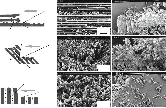
Fig. 7.54 Failure mechanisms during machining of fibre-reinforced plastics
Due to its inhomogeneous structure, the “machining” of fibre-reinforced plastics
involves the formation of highly diverse “chips” compared with metallic materials.
The development of very fine particles made of fragments of t he base material and of
fibres, causing a large amount of dust, is characteristic of machining fibre-reinforced
plastics [Rumm96, Wuer00]. The quality of the machined surface is dependent to a
large extent on the orientation of the fibres in the polymer matrix.
When machining under the 0
◦
-fibre orientation, the particles formed are primar-
ily fibre and matrix packets, which lead to a high level of machined surface quality.
If on the other hand it is machined with a 90
◦
-fibre orientation, particle formation
of single fibres and matrix fragments is predominant. The rim zone of the machined
area near the surface is then characterized by microcracks. Machining with a 45
◦
or 135
◦
-fibre orientation leads to a superimposition of the above particle formation
types. Due to the high levels of mechanical stress, the surface is always heavily
damaged by the cutting edge. This results in high surface roughness values as well
as the formation of very small particles made of fibre and matrix packets.
Measurements of these particles have shown that respirable sizes do exist
(particle < 5 μm) that can have a negative effect on the health of the operator. An
efficient suction and filtering of these particles is therefore absolutely necessary. In
addition, it is advisable to seal off the working area.
The most common machining method when manufacturing components made of
fibre-reinforced plastics are turning, milling and drilling [Köni91, Tras92]. Selection
334 7 Tool Life Behaviour
of the most proper tool should be made in analogy to machining metallic materials
with reference to the technological, economical and ecological limitations.
7.7.2.1 Machining Method: Milling
During machining, the high hardness of glass fibres and in particular of carbon fibres
leads to pronounced wear phenomena on the tools employed.
Such tools must therefore have a high level of resilience against abrasion and
of toughness. Suitable cutting tool materials are ultrafine-grain cemented carbides
(HF), polycrystalline diamonds (DP) or diamond-coated cemented carbide tools
(HC) of application group K10.
To make a precise separation of the fibres possible, the cutting edge must be
very sharp. With respect to the geometry of the cutting edge, it must have a very
low level of raggedness, and the cutting edge radius should be in the range of the
fibre diameter (~10 μm). The grinding of a chamfer on the flank face of the milling
tool has also proved effective. In this way, elastic rebound of the fibres embedded
in the base material can be considerably reduced, reducing thermal and mechanical
stress during machining. A classification into areas of application is made according
to the type of fibres, their length and their percentage in the composite material.
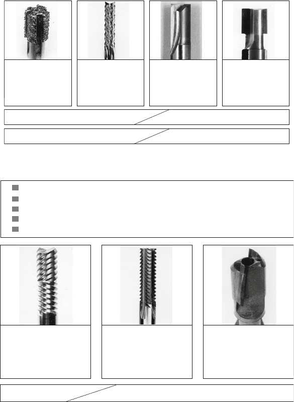
Untwisted two-edged milling cutters with sharp cutting edges should be used to
mill components made of directed long fibres with a large fibre amount, since only
such a tool can separate the fibres cleanly. DP-fitted milling tools are superior to
cemented carbide milling cutters with respect to realizable tool life parameters and
surface quality, but they involve much higher acquisition costs.
Because of the large number of possible material combinations, generalizations
can be made regarding optimal cutting parameters. In many cases, cutting speeds of
800–1200 m/min with moderate feeds per tooth have yielded successful machining
results.
For a high-quality machining of aramid fibre-reinforced laminate, standard cut-
ting edge geometries can be used so long as it is taken into consideration that
the fibres can only be acceptably cut when prestressed. This prestressing can be
achieved with special tools that have been specially designed for this purpose
(Fig. 7.56).
Further tool requirements include a high level of cutting edge sharpness com-
bined with a small cutting edge radius and a high level of rake and flank face surface
quality in order to minimize friction on the workpiece [Köni90b]. As in the case of
glass fibre and carbon fibre-reinforced plastics, the use of tools made of cemented
carbides of application group K10 have also proven effective here.
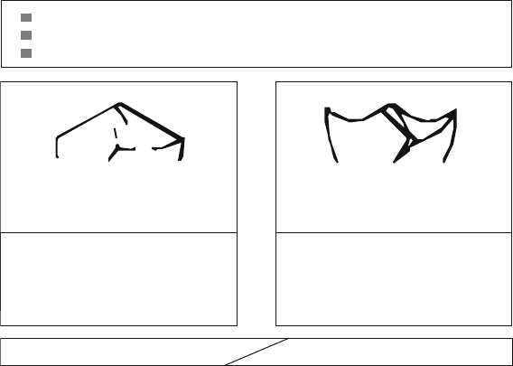
Figure 7.56 shows a distinction made on the basis of the thickness of the com-
ponent to be machined. For thin workpieces, tools twisted in two ways towards
the middle were developed that make it possible to change the distribution of the
machining forces acting on the workpiece. To use these tools successfully, the tool
must be precisely aligned with the workpiece. For thicker components, it is advis-
able to use a two-way mill twisted in contrary directions. In the case of this tool
7.7 Machinability of Non-metals 335
Diamond
toothed
cemented
carbide mill
Double-edged
cemented
carbide mill
Cemented
carbide mill
with DP-
edges
Carbon fibreGlass fibre
Long fibreShort fibre
Electroplated
grinding bolt
Fig. 7.55 Tools for machining fibre-reinforced plastics (GRP, CRP)
Carbide special mill
with contrary fixed
DP-edges
Carbide special mill,
alternating twisted to
the middle
d < 3 mm
d > 3
mm
Carbide special mill,
right-left twisted
Special tool geometry
Low cutting edge radius
r
β
< 10−15 µm
Slight cutting edge chipping
Very high sufrace quality at rake and flank face Rz < 0.8 µm
High wear resistance
Fig. 7.56 Tools for machining a ramid-fibre-reinforced plastics
variation as well, the permanent alternate stress prevents the fibres from eluding the
cutting edge.
The following describes difficulties involved with particles arising when machin-
ing fibre-reinforced plastics (dust, fibre particles).
Figure 7.57 clarifies the high concentration of particles that remain in the work-
ing space even after the machining process and that is only gradually reduced.
Especially the small particle sizes, thoracic (4.5–10 μm) and alveolar (< 4.5 μm)
dusts, remain in the air long after machining is finished and sediment very slowly. As
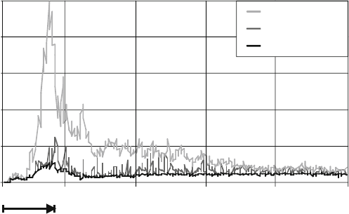
336 7 Tool Life Behaviour
0
50
100
150
200
0 100 200 300 400
500
Time t/s
Milling time
Concentration / (mg/m³)
250
Total dust
Thoracic dust
Alveolar dust
Fig. 7.57 Dust particle size during milling of fibre-reinforced plastics
an experiment, a 90 s long machining process was conducted and the machine was
immediately switched off. It is important to know that even after 500 s, the legally
prescribed fine dust limit of 1.5 mg/m
3
was not yet reached. These particle sizes
are highly carcinogenic, so this limit must be strictly observed. The percentages of
these sizes in the entire volume of dust can be influenced by tool selection and the
cutting parameters. The experiment shows that it is nonetheless absolutely neces-
sary to isolate the working area and to suction off and filter the resulting particles.
7.7.2.2 Machining Method: Drilling
In the case of drilling, it is necessary just as in milling to differentiate in accordance
with the materials to be machined, glass-fibre and carbon fibre-reinforced plastics or
aramid fibre-reinforced plastics. To drill CFP and GFP, highly wear-resistant tools
with standard cutting edge geometries can be used as long as the cutting edge radius
is as small as possible. In many cases, solid cemented carbide tools produce good
results. Tools that are equipped with DP cutting edges are far superior, but t hey can
only be used for manual drilling operations to a limited extent.
Standard tools cannot be utilized to machine aramid fibre-reinforced plastics. In
this case, special cutting geometries should be used in order to guarantee separa-
tion of the fibres while prestressed (Fig. 7.58). Cemented carbide drills with very
positive rake angles have become established for this. Besides a small cutting edge
radius, high l evels of surface quality on the flank and rake faces are required so
that friction between the chip and the tool and between the workpiece and the tool
reduces potential adhesion of the material on the cutting edge.
Potential surface roughness depends heavily on the type and length of the fibres.
When the tool is rotated, all fibre lengths are always cut, so that, depending on the
orientation of the fibres, there is a highly aberrant surface formation in the drill hole.
7.7 Machinability of Non-metals 337
Special, macroscopic
cutting wedge geometry
Side rake angle 30° .. 35°
Side clearance angle 10° .. 14°
Rear clearance angle 0°
Tool cutting angle 125° .. 140°
Side rake angle 20° .. 30°
Side clearance angle 10° .. 12°
Drill point angle 120°
Conventional macroscopic
cutting wedge geometry
AFRP
CFRP und GFPR
Low cutting edge radius
High surface quality at rake and flank face
High wear resistance
Fig. 7.58 Tools for drilling fibre-reinforced plastics
It is characteristic of the material that, in the case of fibre-orientations of
105–135
◦
with a simultaneous compressive load, only very poor surface qualities
can be realized. As opposed to CFP and GFP, there are no fibre fractures in aramid
fibre-reinforced plastics, but the fibres are pulled far out of the cut surface and
bent against the cut surface. This is due to the tough material properties and poorer
adhesion of the aramid fibres to the base material.
Chapter 8
Process Design and Process Monitoring
8.1 Finding Economical Cutting Parameters
8.1.1 Cutting Parameter Limits
The further development of workpiece materials and cutting tool materials and
the increasing automation of machine tools demand an occasional correction of
machining standard values.
Standard values should be determined under consideration of machinability and
provide reference data concerning depth of cut, cutting speed, feed and the expected
tool life parameters for the given tool life criteria. Variation in the machinability of
a material of the same standard designation but different batch can be larger than
three to one in extreme cases. This ratio is the more unfavourable the larger the
permissible wear and the higher the cutting speed [Kluf83]. For an optimal cutting
value determination, the tool life parameters and wear properties of the tool are the
most important criteria for evaluating the tool life behaviour of a material/cutting
tool material combination [Köni71].
Generally, widths of flank wear land of VB = 200−800 μm are permitted for
flank face wear when cemented carbides are used. The tool life criterion for crater
wear should be determined as a function of the feed f with the following equation:
KT = 0.06 + 0.3 · f (8.1)
In addition to tool wear, the other main evaluation parameters of machinability –
the cutting force, surface quality and chip form – also serve, depending on the case at
hand, as tool life criteria. When determining the cutting parameters, the limits of the
system workpiece/cutting medium/tool/machine must be taken into consideration.
Specification of these limit values refers to the description of the cross-section of
undeformed chip using the theoretical parameters uncut chip thickness h and unde-
formed chip width b and must be converted in accordance with geometrical relations
that are true for the respective cutting process into the technical parameters depth of
cut a
p
and feed f (Chaps. 9 and 10).
In order to obtain the largest possible volume removal rate within a given tool life,
first a depth of cut a
p
should be selected that is as large as possible provided it is not
339
F. Klocke, Manufacturing Processes 1, RWTH edition,
DOI 10.1007/978-3-642-11979-8_8,
C
Springer-Verlag Berlin Heidelberg 2011

340 8 Process Design and Process Monitoring
Table 8.1 Maximum of
undeformed chip width
Tool included angle ε
r
/
◦
Chip width b
80–90 2/3 · cutting edge length
60 1/2 · cutting edge length
35–55 1/4 · cutting edge length
already defined by the machining allowance to be lifted in one cut. A large depth of
cut reduces the number of required steps, so that besides the primary processing time
(Sect. 8.1.2), the secondary processing time for lifting, returning and reengagement
is economised.
The maximum depth of cut a
pmax
is limited by the stability of the tool’s cutting
edge. For roughing, tools with a large tool included angle ε
r
are used. The rules of
thumb given in Table 8.1 serve as the standard values.
Larger depths of cut or undeformed chip width can lead to cutting edge fractures.
After determining the depth of cut, the feed should be set as large as possible in order
to minimize the primary processing time. The smaller influence of feed on wear
formation compared with cutting speed and the fact that specific cutting force is
reduced with increased feed both speak for this sequence in determining the cutting
parameters. In this way, the machine’s power can be exploited more fully.
In addition to the maximum and minimum permissible feed of the machine, tool
limits must again be considered in selecting the feed. In order to avoid unmachined
areas on the workpiece, the following inequality can serve as a guide:
f
max
≤ r
ε
(8.2)
The lower feed limit is determined using the minimum chip thickness h
min
, which
is a function of the stiffness of the system workpiece/cutting medium/tool/machine
and is intended to guarantee chip removal especially in the case of rounded off
or chamfered cutting edges. Following S
OKOLOWSKI [Soko55], the following can
serve as a standard value, for turning for example:
0.25 <
h
min
r
n
< 1.125 (8.3)
This minimum chip thickness can be limited both by the material (e.g. in the
case of austenitic steels, which have a propensity to strain hardening) and by the
tool cutting edge form. For example, coated indexable inserts always have a cutting
edge rounding due to manufacturing conditions, the radius of which is between 20
and 60 μm. In the case of roughing and when interrupted cuts require a large amount
of cutting tool material toughness, these roundings stabilize the cutting edges just
like the chamfer of the rake face. In the case of very small chip thicknesses or chip
widths, the elastic portion is greatly increased during the separation process and
chip removal can no longer be guaranteed.
