Klocke F. Manufacturing Processes 1: Cutting
Подождите немного. Документ загружается.

7.6 Machinability of Non-ferrous Metals 321
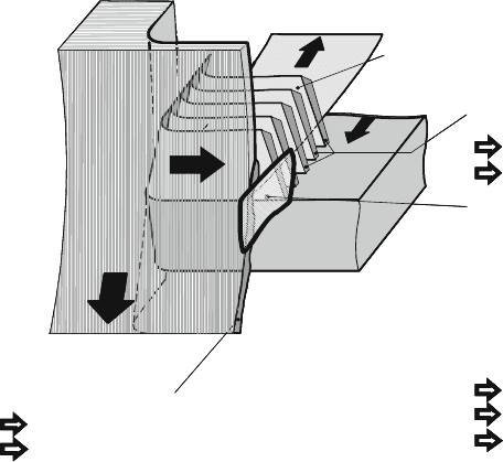
Wear mechanisms that lead to the formation of wear notches include:
• fatigue, cracking and crack development phenomena – initiated by the high ther-
mal and mechanical alternate stress on the cutting tool material as a result of
lamellar chip formation and transverse material flow,
• adhesion – caused by the tendency of the kfz-crystal lattice to form micro-
welding and the mechanical snagging of the chip edge, flowing laterally into the
notches, with the cutting tool material particles,
• abrasion – caused by the solidified, partially sawtooth-shaped chip edge, by the
workpiece edge and the peaks of the feed groove pattern
• tribooxidation – caused by the chemical reaction of the workpiece material and/or
the cutting tool material with components of the surrounding medium.
Wear notches arise as the result of the superimposition and mutual influence
of these individual mechanisms (Fig. 7.44). A clear separation of these mecha-
nisms with respect to their eff ect on total wear is only possible to a certain extent
[Mütz67].
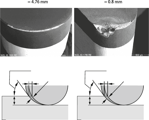
In order to reduce notch wear formation on the major cutting edge, the ratio of
corner radius r
ε
to depth of cut a
p
should be as large as possible and the effective
lead angle in the area of the contact zone end on the major cutting edge as small as
possible. A small lead angle reduces the chip thickness and thus the effect of abra-
sion of the chip edge on the cutting edge as well (Fig. 7.45). A lead angle of κ
r
≤45
◦
has proven effective for turning with tools made of cutting ceramics and CBN.
The effective use of round inserts is explicable in this context. Depending on
the geometry, they exhibit not only a high amount of mechanical stability and thus
Formation of a sawtooth profile
at the edge of the chip lamella
Abrasion
Surface damage
Abrasion
Surface damage
Burr formation at the workpiece edge
Direction of
chip flow
Chip lamella
Flank
face
Direction of
feed motion
Direction of workpiece
rotation
Transverse material
flow following
upsetting of the
chip lamella
Cutting edge sector with :
- high pressures
- high temperatures
- high shear stresses
- high thermal and mechanical
stress gradients
- high thermal and mechanical
alternating stresses
Surface damage
Adhesion
Tribooxidation
Rake
face
Fig. 7.44 Schematic illustration of reasons which cause notch wear at the major cutting edge
[Gers98]
322 7 Tool Life Behaviour
r
ε
RCGX090700T
r
ε
VBGW160408F
a
p
f
h = 0.11 mm
κ
r
= 51
°
a
p
f
h = 0.06 mm
κ
r
= 21
°
Material: Udimet 720Li Cutting speed: v
c
= 250 m/min
Feed: f = 0.15
mm Depth of cut: a
p
= 0.3 mm
Fig. 7.45 Influence of the corner radius on wear formation during turning of a nickel-based alloy
with PCBN
more resistance to insert fracture, but, especially with small depths of cut, they also
generally result in small lead angles. It is thus recommendable to use round index-
able inserts if the machining task allows for it. However, the disadvantage of round
indexable inserts are the high passive forces, which can cause a more pronounced
plastic deformation of the rim zone. Furthermore, the larger contact arc in the area
of the minor cutting edge promotes the formation of wear notches. This has been
observed especially in the case of turning with round indexable i nserts made of cut-
ting ceramics. If very high demands are placed on surface quality, CBN inserts with
corner radii of 0.8–1.2 mm should be used [Gers02, Kloc07a].
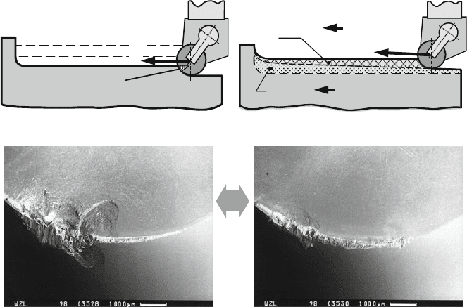
Notch wear formation of the major cutting edge can also be effectively reduced
and tool life improved by the selection of an appropriate cutting strategy. One mea-
sure that has proven very effective particularly in pre-machining with round cutting
ceramics is “ramping”. Here, the material is removed in pairwise pass with contin-
uously decreasing (1st step) and increasing depths of cut (2nd step). As a result of
the continuously changing depth of cut, the effect of the highly abrasive chip edge
is concentrated not on one location of the cutting edge, but rather it extends along a
larger area thereof. In this area, the cutting edge is indeed subject to more wear, but
notch wear proceeds much more slowly, so that the insert can be used for a longer
time (Fig. 7.46).
7.6 Machinability of Non-ferrous Metals 323
I
c
= 261 m
I
c
= 1281 m
Inconel 718, whisker-reinforced cutting ceramic, v
c
= 180 m/min, f = 0.15 mm
Modified: Variable a
p
(ramping)
f
a
p1
: 0.8 1.8 mm
a
p2
: 0.8
Conventional: Constant a
p
a
p
= 1.8 mm
Verschleißkerbe
Notch wear
f
f
0.8 mm
Fig. 7.46 Adapted cutting strategies allow a reduction of notch wear and a longer tool life
(Source: Greenleaf)
Because of the extremely high stress on the cutting edge, milling nickel-based
alloys requires cutting tool materials of high toughness and wear resistance. Because
of the interrupted cut and high heat resistance of the material, the tools are subject
to an extremely high mechanical and thermal alternate stress. As a result, both HSS
and cemented carbide tools can only be used with relatively low cutting speeds and
feeds, so that only low material removal rates can be realized. The milling of such
alloys is thus an extraordinarily time-intensive machining process.
HSS tools are used with cutting speeds of v
c
=5−10 m/min when machining
nickel-based alloys because of their low high temperature wear resistance. Their
excellent toughness properties allow however for the use of relatively large feeds
(f
z
=0.10−0.16 mm). Due to the large number of cutting edges being engaged as
well as the milling cutter with the fine knurled splines, milling with HSS tools is
extraordinarily quiet. Coated end milling cutters made of PM-HSS are therefore
suited above all for roughing nickel-based alloys. With a cutting edge geometry
adjusted to the particular requirements of these materials, high material removal
rates and a large amount of manufacturing safety is possible.
End milling cutters made of superfine and ultrafine-grain cemented carbides have
a much higher level of high temperature hardness than HSS tools. They can there-
fore be used at much higher cutting speeds (v
c
=20−100 m/min), allowing for a
significant reduction of machining times. They are commonly used for average
324 7 Tool Life Behaviour
roughing and especially for finishing operations. When end milling cutters and
inserted-tooth cutters that are fitted with HM indexable inserts are used, the perfor-
mance capacity of the tools is determined to a great extent by cutting tool material
spalling on the cutting edges of the indexable inserts when nickel-based alloys are
machined. They are formed as a result of a mechanical overload of the relevant sec-
tion of the cutting edge. For the sake of a dynamically stable and quieter milling
process, one should strive to have as many cutting edge rows as possible in simulta-
neous engagement. This demand cannot always be fulfilled for the given machining
task due to the design of milling cutters fitted with cutting inserts [Gers02].
If grooves must be generated by rough milling in full groove cut into com-
ponents made of nickel-based alloys, the tools are subject to very high levels of
thermal and mechanical stress. Due to the wrap-around angle of 180
◦
between
the tool and the workpiece, a very strong force component affects the tools in the
feed direction which strongly subjects the end milling cutter to bending. Faults in
shape and dimension on the groove flanks are the result. Due to the high static
and dynamic stress, the tools can only be used in full groove cut at relatively low
speeds (v
c
=20−40 m/min) and axial depths of cut (a
p
=0.5 · D). In the case of
long-protruding tools, the cutting parameters must be further decreased in order to
reduce mechanical stress and the danger of cutting edge fracture and total breakage
of the tool.
Economical alternatives to conventional end milling of grooves into materials
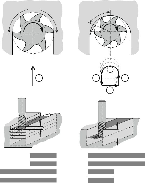
that are difficult to machine include “trochoid milling” (Fig. 7.47) and “plunge
milling”. In the former case, the feed motion of the milling cutter, whose diameter
is smaller than the width of the groove, superimposes an approximately circular
motion. Usually, down milling is used. What is special about this method is that,
as a function of the ratio of milling cutter diameter to groove width and the chosen
feeds in axial and radial direction, the wrap-around angle is significantly smaller
than 180
◦
, thus corresponding to finishing conditions. Trochoid milling leads to a
considerable reduction of mechanical tool loading. As a result, not only the cutting
speed but in particular the axial depth of cut can be significantly increased compared
with conventional groove milling. Especially in the case of slender, long-protruding
tools, the realizable depth of cut is several times more than that of conventional
milling. Because of the larger potential depths of cut, the material volume to be
machined is distributed across a larger cutting edge length. The tools are thereby
used more effectively and tool life is much higher with respect to the amount
of material machined, lowering tool costs drastically. A further advantage of this
method is that the width of the groove that is to be manufactured is independent of
the tool diameter and can be produced accurately in one milling cycle. Since in this
method only low forces act upon the tools on both flanks when entering and exiting,
errors in form and dimension on both groove flanks are extraordinarily few.
By superimposing a wobbling motion, not only straight but also curved flanks
can be created with this method. In the case of plunge milling, the end or plunge
milling cutter is plunged axially into the workpiece with low radial feed. In this
way, the tool is primarily stressed in the axial direction [Kloc04]. The radial tool-
bending forces are, dependent on the radial feed and the corner design of the end
7.6 Machinability of Non-ferrous Metals 325
< 0.5 x Tool-Ø
3 1
4
1
Trochoide milling
Feed motion
a
p
/mm
a
e
/mm
ϕ /°
v
c
/(m/min)
0.2–3
30–60
<= 2 x Tool-Ø
60–120
2
30°-60°
Angle of contact ϕ
**
15–40
≤ 1 x Tool-Ø
180
Conventionel milling
Angle of contact ϕ
180°
**
**
: Direction of
rotation
2 x Tool-Ø
0.5 x Tool-Ø
Fig. 7.47 Trochiod versus conventional end milling
milling cutter, relatively small. By plunge milling, very deep and narrow cavities
can be produced. The disadvantage of this method is that the stress is concentrated
exclusively on the corners of the tool.
When machining materials that are difficult to machine, the performance of an
end milling cutter can be affected significantly by the micro-geometry of the cut-
ting edge as well. In the past, popular opinion held that end milling tools should
have cutting edges that are as sharp as possible to machine materials like nickel and
titanium alloys because of the small realizable cross-sections of the undeformed
chip. Highly positive and sharply formed cutting edges do indeed have good cutting
properties, but, as a rule, the sharper a cutting edge is the greater is its jaggedness
caused by cutting edge spalling. As investigations have shown, the jaggedness of the
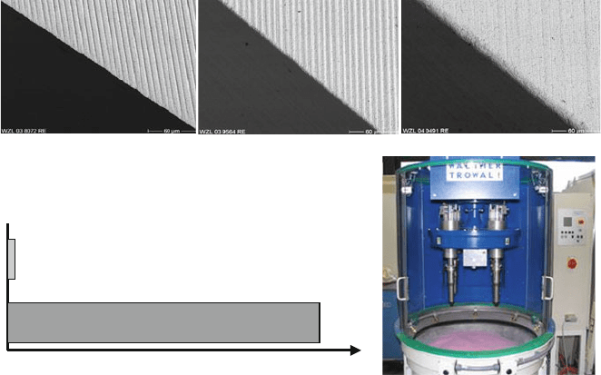
326 7 Tool Life Behaviour
Without CER (sharp-edged)
CER 5 µm
CER 20 µm
Tool life travel path
Without cutting edge rounding (CER)
With cutting edge rounding (CER)
Material: IN100
Tool: End milling cutter, long projecting:
l/d = 6
CER-process: Drag grinding
Fig. 7.48 Influence of the cutting edge rounding on tool wear during end milling of a nickel-based
alloy with long cantilever length
cutting edge – produced as a function of the grinding process, cutting tool material
microstructure and cutting edge geometry – influences the performance capability
of a t ool quite considerably. A small rounding of the cutting edge in the order of
5–20 μm can significantly increase the wear properties of end milling tools, espe-
cially when machining materials t hat are hard to machine (Fig. 7.48). Cutting edge
rounding stabilizes the cutting edge and either evenly smoothens or removes small
defects caused during manufacture by grinding in the form of micro-fractures, loos-
ened cemented carbide crystals or micro-cracks. In this way, an even wear zone is
formed on the cutting edge, and wear progresses in a continuous fashion. The cut-
ting edge can be prepared in different ways. Besides drag finishing, used on the t ools
shown in Fig. 7.48, brushing, jetting with abrasive media or cutting edge rounding
with laser beams can be used [Denk05].
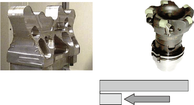
The use of cutting ceramics based on silicon nitride and whisker-reinforced alu-
minium oxide when rough or finish milling with inserted-tooth cutters has opened a
new dimension in the milling of Inconel 718 (Fig. 7.49). Applicable cutting speeds
extend to more than 1000 m/min and are thus many time more than those com-
monly used for milling with cemented carbide. At a cutting speed of v
c
=800 m/min
and a f eed of f
z
=0.1 mm compared with cemented carbide with v
c
=40 m/min
and f
z
=0.06 mm, this means an increase in cutting performance by a factor of 33
[Krie02, Gers02].
The causes of such a high performance capacity are based on the chemical and
mechanical stability of ceramics. However, the use of cutting ceramics still has
restrictions because of their limited toughness. A sufficiently high level of toughness
7.7 Machinability of Non-metals 327
Cutting tool material:
CA + SiC-whisker
Matrix: Al
2
O
3
+ ZrO
2
Engine bracket of
Inconel 718, 28HRC
v
c
= 1310 m/min
Trockenschnitt
Milling with cemented carbide: 59 h
Milling with ceramic: 14 h
– 76 %
Time:
Milling with ceramic: 14 h
f
z
= 0.076 − 0.10 mm
v
f
= 1.8 − 2.0 m/min
Fig. 7.49 High-performance milling of Inconel 718 with cutting ceramics (Source: Kennametal)
is necessary to avoid cracks and fractures especially in the case of interrupted cut.
Reinforcing ceramic cutting tool materials with needle-shaped ß-Si
3
N
4
crystals
or with SiC whiskers meets this requirement and contributes considerably to the
improvement of toughness. The needle-shaped crystals or whiskers embedded into
the ceramic matrix can transfer tensile stress and thus reduce cracking. The energy
required to loosen these crystals delays crack development. At the needle-shaped
crystals, cracks extending in the matrix are forced into energy-consuming alter-
nate routes, reducing the speed of crack development. These effects increase the
toughness of the cutting tool material and its dynamic loading capacity. [Krie02].
7.7 Machinability of Non-metals
The most technically important non-metals that are commonly machined include
graphite and fibre-reinforced plastics.
7.7.1 Graphite
Graphite is – like diamond – a modification of carbon and is crystallized in a
hexagonal lattice structure. It is manufactured by coking coal. The fabrication pro-
cess allows for a considerable degree of freedom in process design, whereby the
resulting material properties can be to a great extent adjusted to the specific applica-
tion. Industrial graphite is characterized by good electric and thermal conductivity
and is temperature-resistant up to 3000
◦
C. Further properties such as density, ther-
moshock resistance, corrosion resistance and chemical resistance can be adjusted
to a large extent and across a large range by the manufacturing process. The main
328 7 Tool Life Behaviour
application areas of graphite are above all in those with high operating temperatures
as electrodes, heating conductors, sealing and sliding elements as well as support
materials in
• the semiconductor industry (e.g. the preparation of ultrapure silicon),
• non-ferrous metal production (e.g. heating elements in furnace installations),
• energy transfer (e.g. sliding contacts),
• machine construction (e.g. sliding rings) and
• the metalworking industry (e.g. electrodes for spark erosion).
Graphite grains are 3–15 μm large and firmly integrated in a coked binder matrix.
This structural composition leads to brittle material properties with a removal mech-
anism which differs fundamentally from that of steel processing. This implies
especially that experiences made in steel machining are difficult or impossible to
relate to graphite processing with geometrically defined cutting edges. There is no
plastic deformation in graphite upon penetration of the tool cutting edge into the
material. Therefore, there is no “chip formation and removal” such as is found when
machining ductile materials. Instead, the following effects predominate:
• Compressive stresses introduced under the tool cutting edge that are reduced by
secondary cracking lead to material disintegration, and there is also a pronounced
formation of ultrafine dust.
• Due to leading crack fronts, there is a chipping of graphite particles and formation
of fracture planes in front of the tool cutting edge (Fig. 7.50).
Depending on the cutting values and engagement conditions of the tool, one of
these two effects is predominant. By increasing the cross-section of undeformed
chip and the cutting speeds, there is a reduced lowering of stress by secondary
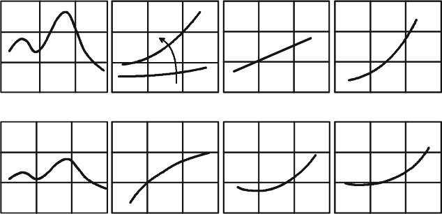
Dimension deviation
Δ
Surface finish Rz
Rotational speed n
Rotational speed n
Feed per tooth f
z
Feed per tooth f
z
Contact width a
e
Contact width a
e
Depth of cut a
p
Depth of cut a
p
a
p
Fig. 7.50 Qualitative influences on the machining of graphite electrodes
7.7 Machinability of Non-metals 329
cracks, so crack development and thus the development of larger fracture planes
are favoured.
The previously described effects influence the obtainable surface quality and tool
wear differently. Surface roughness increases with the grain size of the graphite and
with increasing chip cross-section by enlarging the width of cut a
e
, feed per tooth
f
z
and depth of cut a
p
as well as increasing the cutting speed v
c
by the formation of
crack fronts leading from the cutting edge.
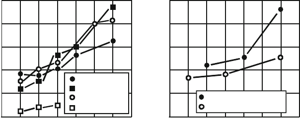
The dominant wear mechanism in graphite machining is abrasion due to the flow
of ultrafine dust and friction (wear type: particle jet erosion). Since by increasing the
cross-section of undeformed chip the formation of ultrafine dust is reduced, this also
reduces tool wear considerably. In general, wear is reduced by all measures taken
to remove graphite dust quickly from the machining area (blowing, dust extraction).
The obvious use of wet cutting has negative effects however, since the resultant
abrasive suspension increases tool and machine wear. When roughing with high
material removal rates of electrodes soaked in dielectric, investigations have shown
a clear increase in tool life parameters due to the reduction of ultrafine dust, which
however was not reproducible in the case of finishing with small chip cross-sections.
Tool selection in graphite machining is usually made in the context of wear min-
imalization. Abrasion by means of hard graphite dust (particle jet abrasion) leads to
craters and fractures on the rake face. Friction contact promotes wear on the flank
face by the abrasive washing of the cemented carbide matrix. Improving tool life
with coatings such as are familiar in steel processing (e.g. TiAlN, TiN) is only pos-
sible to a certain extent. The only effective protection against the abrasive effect of
graphite dust is polycrystalline diamond (DP) as cutting tool material or the use of
diamond coatings because of their high levels of hardness (Fig. 7.51).
Cutting parameters:
f
z
= 0.05 mm
a
p
= 3 mm
a
e
= 12 mm
Material: EK85
Grain size: 13 µm
Tool: End mill
D = 12 mm
z = 2
25
20
15
10
5
0
210012009006003000 1500
HM K10
HM P25
HM K10 (TiN)
Cermet
Length of cut per edge L
fz
/mm
210012009006003000 1500
250
200
150
100
50
0
K10, diamond coated
PKD CD10
1800
1800
Cutting speed v
c
/ (m/min)
Length of cut per edge
fz
L
fz
/ mm
Cutting speed v
c
/ (m/min)
Fig. 7.51 Wear behaviour of different cutting tool materials
330 7 Tool Life Behaviour
The rounding of the cutting edge associated with coating causes increased chip-
ping of graphite particles and leads to a somewhat worsened surface quality. By
using a positive tool inclination angle, particle jet wear is reduced due to the flatter
inflow and graphite removal from the machining location is favoured. Increasing
the tool orthogonal clearance angle lowers wear. Weakening of the cutting edge is
of secondary importance due to the low resultant force. Since the material attributes
of graphite differ fundamentally from those of metallic materials, other machining
strategies can and must be employed in order to get the best results. The goal of
roughing is a high material removal rate with high tool life and constant residual
machining allowance. The low resultant force in graphite machining allows for a
groove cut D = a
e
) with large depths of cut. To reduce turnaround motions, an
envelope-curve-limited cut distribution should be made. The goals of finishing are
a high surface quality and precision of contour as well as low machining times and
high tool life. As in steel machining, a distinction must be made between different
machining and engagement situations. When machining curved surfaces, up milling
with a falling machining direction leads, as opposed to steel machining, both to bet-
ter surfaces and to higher tool lives. On steep contour areas, machining with a falling
direction is preferable to a rising one, since in the former case stress on the milling
cutter is in the direction of maximum tool stiffness and cutter-drift can be reduced.
When machining slim webs, there is a danger of fracture on the workpiece’s edges.
In this case, the use of tools with a negative tool helix angle is recommendable
in order to lower the risk of fracture due to tensile stresses. Up milling reduces
the risk of fracture upon entry of the tool, just as down milling upon the tool’s
departure. In order to avoid these contrary demands, it is recommendable to work
completely in an up milling process and to place the tool exit in the allowance still to
be machined of a neighbouring surface. Especially when thin tools are used, mate-
rial accumulation in the area of the grooves requires pre-processing along the groove
before the neighbouring surfaces can be finished and the groove pulled behind.
The danger of tool-drift is higher with smaller grain sizes and increasing graphite
hardness.
In summary, it is clear that the material properties of graphite, with its brittle
attributes, demand a fundamentally different process design in the case of milling.
The low machining forces and low thermal stress make it possible to use high cut-
ting speeds and feed velocities and thus place special demands on the tool/process
kinematics/machine tool system. To reduce wear, diamond-coated cemented carbide
milling cutters with cutting edge rounding and a large tool orthogonal clearance or
PCD milling cutters should be utilized. The machine tool used must be capable of
implementing the high potential process parameters even when machining complex
geometries. To do this, high spindle rotational speeds and a high axial dynamic are
required, as well as a rapid NC control. Dust formation demands efficient ventilation
and filtering in an encapsulated working space. During NC programming, machin-
ing strategies that are adjusted to the peculiarities of graphite should be implemented
in order to guarantee consistent component quality.
Figure 7.52 shows two graphite electrodes typically used in tool and mould con-
struction. In the case of sinking electrodes such as are used in the manufacture of
