Hughes M.P., Hoettges K.F. (Eds.) Microengineering in Biotechnology
Подождите немного. Документ загружается.

In this case, the detection area is directly defined by the electrode
geometry within the capillary channel. This approach reduces
stray capacitances and thus increases the device operating band-
width toward higher frequencies. Measurements at the higher
end of the b-dispersion (see below) are then possible. Small
channel cross-sections permit sequential tracking of cells along
the channel and the integration of features such as sorting by
partitioning the channel length for successive operations. Small
microelectrodes result in an apparent dilemma; on the one hand,
a higher sensitivity results from the higher field line concentra-
tion around the cell. On the other hand, the high interface
impedance (due to the electrical double layer) makes measure-
ment at low frequency more difficult. To alleviate this problem
there are some techniques to increase the effective surface area of
microelectrodes based on nanoporous films such as platinum
black, iridium oxide, or titanium nitride (27, 28).
Nanoporous films can be deposited on a seed electrode through
an additional fabrication step. For platinum black, which uses
electro-deposition, the effective surface area increase can reach
100- to 1,000-fold, but in practice it is particularly difficult to
obtain a high reproducibility of the final interface impedance.
Alternatively, the use of a sputtered iridium oxide film (IrOx)
demonstrates reproducible results and large effective surface area
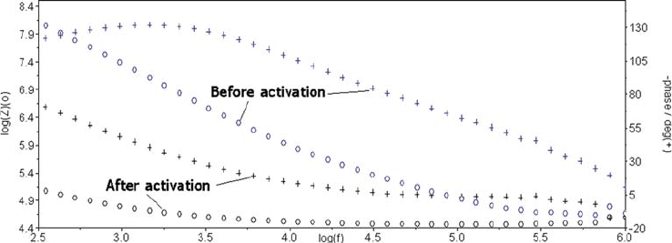
increase following activation (29). The activation is simply per-
formed by applying a cyclic voltametry step of 10–20 cycles of 3 V
at 0.1 Hz to the microelectrodes with the microfluidic channel
filled with NaCl. It can be seen in Fig. 7.3 that after activation the
low frequency cut-off point (taken at a 45 phase) is decreased
from 100 kHz down to the 1 kHz range. The electrodes phy-
sical dimensions are in this case 20 40 mm.
Another issue arises from the inhomogeneous current density,
be it either within the channel constriction (i.e., aperture) or if
small electrodes are used between the closely placed electrode pair.
Fig. 7.3. Frequency response analysis showing impedance amplitude and phase of a pair of IrOx microelectrodes
as measured before and after the activation procedure.
156 Gawad et al.
This inhomogeneity can bias the detection signal peak, as a func-
tion of the particle’s trajectory, as it passes through the measure-
ment volume. In traditional Coulter systems, the length and shape
of the aperture plays an important role in controlling the unifor-
mity of the signal shape and this has been extensively studied (30).
Similar studies may be performed for the integrated chip approach
with embedded microelectrodes. A complex dielectric model is
used to determine the change in electric current between a pair of
electrodes due to passage of a biological cell. The influence on the
dielectric spectrum of different cell properties, such as membrane
capacitance and cytoplasm conductivity is of particular interest.
The measurement volume is located between a pair of facing
microelectrodes in a microchannel filled with a saline solution. A
3D finite element model is used to determine the electric field in
the channel and the resultant changes in charge densities at the
measurement electrode boundaries as a cell flows through the
measurement volume. The charge density is integrated on the
electrode surface to compute the displacement current and the
channel impedance for a given applied alternating electrode vol-
tage and frequency. The excitation signals are taken to be of
suitably low frequency and low applied voltage, allowing the
quasi-static approximation and linear behavior of the system to
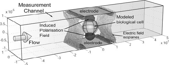
be assumed. In the present example, the measurement volume
geometry details are for the specific case of a sensor with a channel
of 20 20 mm
2
cross-section and two facing electrodes, 20
20 mm
2
in area, on opposite walls of the channel (Fig. 7.4). These
channel dimensions are chosen in order to determine the sensitiv-
ity of a sensor, which could accommodate cell diameters up to
15 mm without clogging the channel.
Fig. 7.4. Diagram of flow cytometry measurement in a microchannel with integrated
microelectrodes. The modeled cell passes between the electrode pair, altering the
electric field distribution for different excitation frequencies, thus giving rise to a change
in the measured channel impedance spectrum. The electric field density in the channel
represented here by isosurfaces shows typical polarization effects of the Maxwell-
Wagner type (caps on the top and bottom of the modeled cell) and the inhomogeneous
field due to the electrode pair. (From Gawad et al. (31) – Reproduced by permission of
The Royal Society of Chemistry)
Impedance Spectroscopy, Optical Analysis of Single Biological Cells 157
A dielectric sphere of equivalent complex permittivity is used
as a simplified model to describe a biological cell. The model
includes various geometrical parameters of the cell, such as size
and position in the channel. Using such a model it is shown that
given a reasonable size and placement of the cell along the center
line of the channel, a good signal reproducibility can be obtained.
Also using analytical methods, such as conformal mapping, com-
pensation factors can be found, depending on the sensor geome-
try, to account for the fringing effect and non-uniformity of the
electric field. Numerical approaches have been used to determine
the practical limits of this compensation method (31).
4.1.3. Cell Detection Area
and Differential
Measurement
In practice, the measurement area of the chips contains two mea-
surement volumes (pairs of electrodes) in close proximity. In the
measurement area the channel width is reduced in order to
decrease the detection volume and thus increase the electrical
sensitivity of the system to the passage of the cell. This restriction
also decreases the chance of having two cells entering the measure-
ment area simultaneously. The electrode areas are typically 20
40 mm
2
and channel cross-section 20 40 mm
2
. The distance
between the two electrode pairs is 60 mm.
The particle or cell moving under pressure-driven flow succes-
sively pass through the two electric field regions, thus consecu-
tively modifying the current through each detection volume. The
use of a differential measurement scheme significantly reduces
the measurement noise; small thermal fluctuations or variations
in the composition of the suspending fluid are thus cancelled out.
The chip is connected to a circuit which uses differential electro-
nics to amplify the small difference of current passing through the
two sensors. This approach allows rejection of the common mode
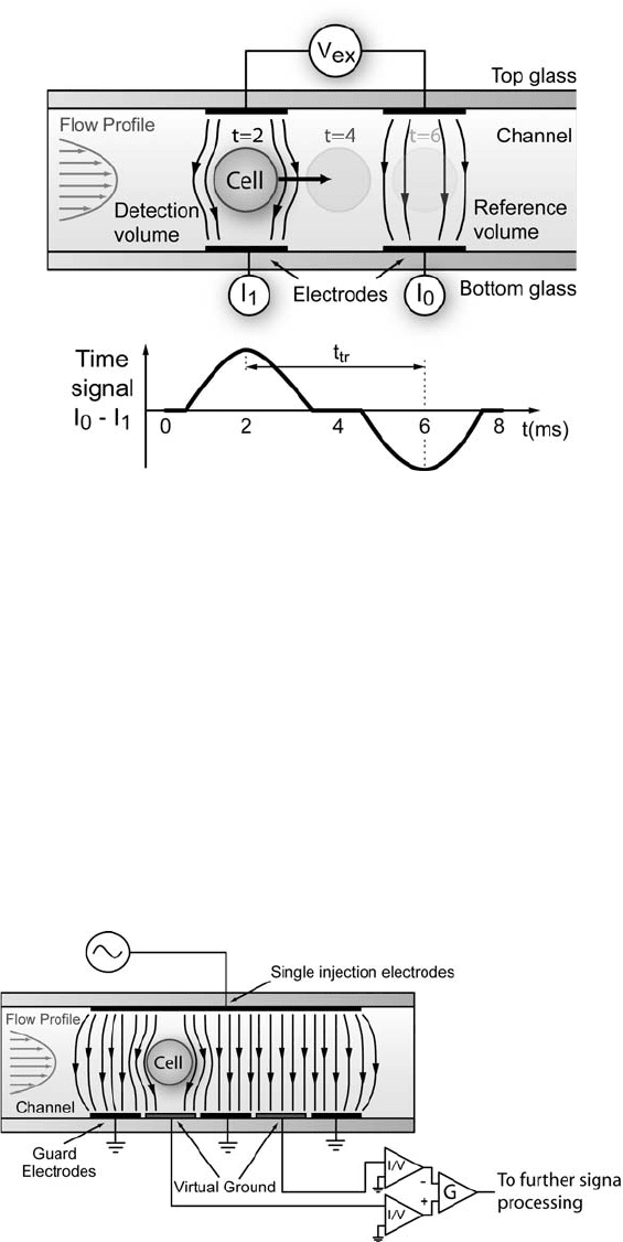
signal early on, avoiding saturation of the amplifiers. A double
peak (one positive and one negative) electrical signal shape is
thus obtained for each passing cell (Fig. 7.5). This approach offers
many advantages compared to a non-referenced measurement
technique in terms of ground level stability and signal amplifica-
tion. The cell speed within the detection channel is obtained by
dividing the center-to-center distance between the detection
volumes by the transit time t
tr
separating the two measured
peaks. This method also presents some advantages in terms of
robustness compared to a single peak width measurement, as it is
less sensitive to the cell size or shape.
4.1.4. Further Techniques
4.1.4.1. Guard Ring
The addition of a guard ring in order to straighten the electric field
lines around the current sensing electrodes is a practical approach
that addresses the issue of the electric field uniformity and permits
simplification of the calculation of the cell geometric factor. The
use of grounded guard electrodes in conjunction with current
sensing electrodes connected to a virtual ground in auto-balanced
158 Gawad et al.
bridge configuration is preferred (Fig. 7.6). This is because at
higher frequencies (MHz and greater) it is difficult to implement
non-phase lagging followers to drive active guard electrodes, as
would be required by a traditional bridge electrical circuits. This
amplification approach also reduces the effect of the stray capaci-
tances as there is no current leakage from the current sensing leads,
at a virtual ground potential, to the ground shielding or guard
electrodes leads.
Fig. 7.5. Cell detection principle and expected electrical differential current signal for a
passing cell. The detection and reference volumes switch as the cell passes through
each. The cell speed in the measurement channel is computed by measuring the transit
time t
tr
separating the two peaks. The bottom electrodes are kept at a virtual ground
potential.
Fig. 7.6. Principle and geometrical approach to implement guard electrodes in a
differential auto-balanced amplification scheme.
Impedance Spectroscopy, Optical Analysis of Single Biological Cells 159
4.1.4.2. 4 Point Differential
Electrodes
An alternative method to that of nanoporous modification of
electrodes surfaces, to increase the effective charge density of the
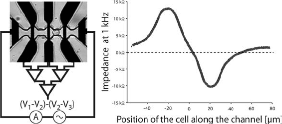
electrodes, is the use of a 4-point differential electrode configura-
tion (32). In this configuration an alternating voltage is applied
between two large microelectrodes placed at either end of the
channel and the injection current is measured. Three pickup elec-
trodes are placed symmetrically in the channel. The differential
voltage drops between the pickup electrodes are then amplified
and compared yielding the impedance variation due to the pre-
sence of the cell. This technique has been shown to work well up to
10 kHz using the geometry shown in Fig. 7.7a.InFig. 7.7b the
impedance variation measured at 1 kHz is represented for a passing
cell as a function of its position in the channel.
The pickup electrodes surface capacitance, due to the double
layer, still subsists in the tetrapolar measurement scheme. But since
the input impedances used in the amplification is high only negli-
gible amounts of current flow through those electrodes. The
measured transient changes in voltage at the electrode thus corre-
spond to those taking place in the liquid bulk with minimal voltage
drops due the double layer capacitance.
4.2. Optical Detection The chip substrate consist of optical quality glass, it is therefore
possible to perform optical measurements on the cells as they pass
through the channel. Details of such an optical system are shown
in Fig. 7.8. This system was designed to measure fluorescence
from single cells at three different wavelength ranges. To opti-
cally excite the cells light from a 532 nm (solid state YAG) and a
633 nm (HeNe) laser is coupled into the channel using a free-
space optics setup and a standard microscope objective. The laser
beams are combined and pass through a beam expander into an
infinity corrected objective lens ( 20, 0.5 N.A. Nikon). For
Fig. 7.7. (a) 4-point differential measurement principle. (b) Measured impedance signal.
(Figure courtesy of T. Braschler)
160 Gawad et al.
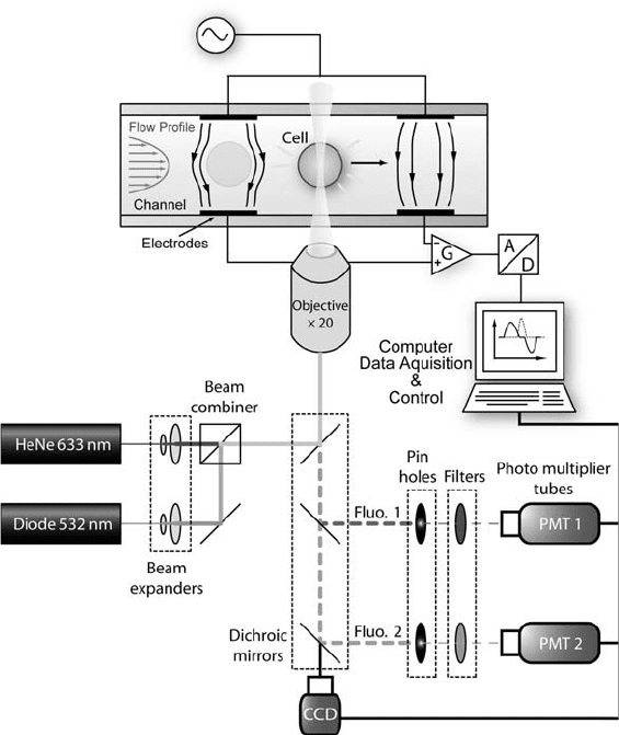
detection the fluorescent light emitted from the cells is collected
by the same objective lens is spectrally and spatially filtered by
passing through dichroic mirrors, band pass filters, and lens and
pinholes positioned in front of photomultiplier tubes (Hama-
matsu). The intensity of the light at the focal point of the objec-
tive (optical detection zone in the channel) is typically 600 mW.
The emission filters have center wavelengths of 585 nm and
675 nm and a longpass filter with cutoff at 710 nm (Chroma,
Rockingham, VT, USA).
4.3. Sample Preparation
and Chip Maintenance
Sample preparation is certainly one of the most time consuming
and critical aspect of the system operation. The quality of the
sourced sample is important as is proper lab technique for cell
harvesting, filtering, labeling, and washing. The large amount of
cell debris, DNA fragments or other substances, which accumu-
lates on the channel walls necessitates regular cleaning of the
microchannel.
Fig. 7.8. Schematic of the single-cell optical detection system using two excitation lasers
and up to three emission detectors.
Impedance Spectroscopy, Optical Analysis of Single Biological Cells 161

For cultured cells, trypsin is generally used to re-suspend cells
adherent to the petri dish wall. For cells grown in suspension
mechanical action using a pipette or gentle vibration is sufficient
to separate large cluster of cells into single units. Mesh filters of 50
microns are used to avoid clogging of the capillary channel with
large debris.
Another issue is due to the time taken for the measurement,
generally over 1 min to measure a few hundreds of cells. With the flow
speed being rather low in the larger parts of the channel sedimenta-
tion and cell adhesion to the bottom glass surface of the channel or
tubing can occur. To reduce sedimentation a small percentage of
Ficoll 400 a long chain poly-sucrose molecule can be used to obtain
the condition of neutral buoyancy as suggested by Holmes et al. (33).
Ficoll400 is useful in that is does not effect the osmotic balance of the
cells. In general, a temporary flow speed increase between measure-
ments is sufficient to resuspend cells that have sedimented and tem-
porarily adhered to the walls. A cell dilution of up to 10
6
cells ml
–1
was found to be suitable to reduce the occurrence of doublet events
(two separated cells flowing simultaneously through the detection
zone) while still achieving a steady stream of cells.
4.4. Dielectric
Properties of a
Suspension of Cells
The determination of the equivalent dielectric properties of a
randomly distributed suspension of homogeneous particles started
with the work of Maxwell, who originally considered conductivity,
and was extended to complex permittivity by Wagner. In deriving
the model Maxwell considered a number N
p
of non-interacting
particles of radius R, placed in the spherical volume of radius R
0
.
The sum p
sum
of their effective dipole moment p
eff
contributions is
simply obtained by
p
sum
¼ N
p
p
eff
[2]
Considering a sphere filled with a homogeneous material with a
complex permittivity
"
2
, suspended in a liquid of complex permit-
tivity
~
"
1
, the effective dipole moment of the sphere p
sphere
is then
given by
p
sphere
¼ 4pR
0
"
1
~
"
2
~
"
1
~
"
2
þ 2
~
"
1
[3]
A complex permittivity
~
" is defined as
~
" ¼ "
r
i
!"
v
[4]
is the conductivity of the material, "
r
is the relative permittivity,
"
v
the permittivity of free space, and ! the angular frequency.
By equating the relations [2] and [3], the complex form of
Maxwell’s expression gives an expression for the equivalent com-
plex permittivity of the suspension
~
"
equ
.
162 Gawad et al.
~
"
equ
~
"
1
~
"
equ
þ 2
~
"
1
¼
~
"
2
~
"
1
~
"
2
þ 2
~
"
1
[5]
The volume fraction ’ is defined by ¼ N
p
R
3
=R
3
0
. An elegant
formulation of the equivalent complex permittivity
~
" is given by
Jones
15
~
"
equ
¼
~
"
1
1 þ 2
~
Kð
~
"
2
;
~
"
1
Þ
1
~
Kð
~
"
2
;
~
"
1
Þ
[6]
where
~
K is the complex Clausius–Mossotti factor which contains
the magnitude and phase information of the dipole representing
the cell defined as
~
K ¼
~
"
2
~
"
1
~
"
2
þ 2
~
"
1
[7]
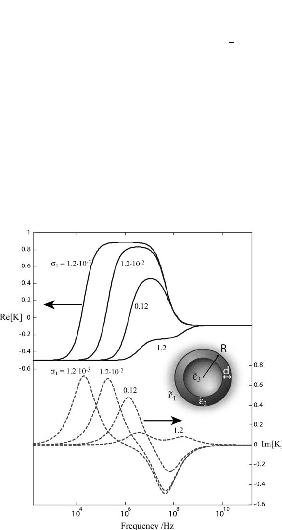
An expression for more complex particle models including multi-
ple shells is obtained by substituting the corresponding Clausius–
Mossotti factor to account for additional relaxations in the dielec-
tric properties of the cell (Fig. 7.9).
Fig. 7.9. Frequency dependence of the real and imaginary part of the Clausius–Mossotti
factor for a shell-covered sphere in suspending media of different conductivity, with
parameters
1
¼1.2
.
10
–3
–1.2 Sm
–1
,
2
¼1
.
10
–8
Sm
–1
,
3
¼0.5 Sm
–1
, "
1
¼78"
v
,
"
2
¼ 10"
v
, "
3
¼ 60"
v
, R ¼ 2 mm, d ¼ 10 nm.
Impedance Spectroscopy, Optical Analysis of Single Biological Cells 163

The number of theoretical relaxations (drops in permittivity
with increasing frequency) is equal to the number of interfaces in
the cell model. In particular, the single-shell model displays two
relaxations: one for the interface between the external medium and
the membrane and the second for the membrane internal interface
with the cytoplasm.
Even in the simple case of a sphere covered by a single shell, the
expression can get rather intricate and can become impractical for
studying experimental data. Pauly and Schwan were the first to
publish a convenient set of equations detailing the dispersion
parameters for such a model (34). Although the single-shell
model theoretically gives two separate relaxations when consider-
ing the full Pauly and Schwan expressions, permittivity measure-
ments in physiological saline solution show only one relaxation
in practice. Its characteristic frequency is located in the MHz
range and is related to the time needed to charge the membrane
(subscript 2) through the intra-(subscript 3) and extracellular
(subscript 1) media. The simplified expressions describing this
dispersion are
s
¼
1
ð1 Þ
1 þ =2
; [8]
1
¼
1
1 þ 2ð
3
1
Þ=ð
3
þ 2
1
Þ
1 ð
3
1
Þ=ð
3
þ 2
1
Þ
; [9]
"
s
¼ "
1
ð1 =2Þ
ð1 þ Þ
þ " with " ¼
9
"
v
2 þ ðÞ
2
RC
2
[10]
"
1
¼ "
1
ð1 þ 2Þ"
3
þ 2ð1 Þ"
1
ð1 Þ"
3
þð2 þ Þ"
1
; [11]
and
T ¼
1
2pf
c
¼ RC
2
1
3
þ
1
1
1 ðÞ
2 þ ðÞ
: [12]
Subscript s relates to the dielectric properties of the suspension at
low frequencies while subscript 1 relates to the values at high
frequency. T is the characteristic time constant and is related to the
characteristic frequency f
c
of the dispersion. The membrane capa-
citance C
2
¼ "
2
"
0
=d is a function of the membrane thickness d and
permittivity "
2
. The approximations involved here are small shell
thickness d R, low shell conductivity
2
1
;
3
, and the
assumption that
1
!"
1
"
0
and
3
!"
3
"
0
.
The second dispersion is observed with a suspending medium
of low conductivity at a higher frequency range. The membrane
capacitance is considered short-circuited and the observed relaxa-
tion is due to the Maxwell-Wagner dispersion resulting from the
164 Gawad et al.
difference in permittivity between the relatively conductive cyto-
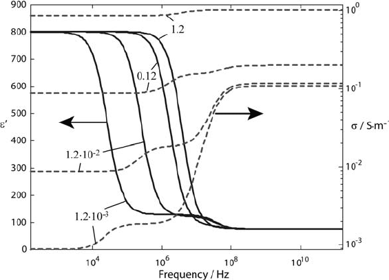
plasm and the insulating suspending solution. The permittivity and
conductivity of a suspension of shell-covered particles is plotted in
Fig. 7.10 for suspending media of different conductivities.
Determining the optimum suspending medium conductivity in
terms of device sensitivity is an important question. For practical
operation, it would be convenient to pass cells through the mea-
surement system using standard culture medium or buffered saline.
Nevertheless, as it represents an important adjustable parameter it is
essential to determine whether the measurement sensitivity would
benefit from resuspension of the sample in a medium of different
conductivity. With this in mind the different approaches of AC
electrokinetics and AC dielectric spectroscopy are compared below.
4.4.1. AC Electrokinetics In AC electrokinetic techniques such as DEP and ROT, the move-
ment of a cell under the influence of an applied electric field is used
to obtain information about the complex electrical properties of
the cell. The magnitude of the observed displacement and related
forces are a function to the cell’s dielectric properties. For DEP and
ROT experiments, sucrose is generally added to the solution (to
control the osmolarity of the solution) when working at decreased
conductivities (1.210
–2
Sm
–1
). From the observation of the
Clausius–Mossotti factor frequency dependence for the single-
shell cell model in Fig. 7.9, it is clear that separation and measure-
ment techniques based on AC electrokinetics benefit from a low
conductivity of the suspending medium:
Fig. 7.10. Permittivity and conductivity spectrum for a shell covered sphere in different
suspending media conductivities, with ’ ¼0.2,
1
¼1.210
–3
–1.2 Sm
–1
,
2
¼110
–8
Sm
–1
,
3
¼ 0.5 Sm
–1
, "
1
¼ 78"
v
, "
2
¼ 10"
v
, "
3
¼ 60"
v
, R ¼ 2 mm, d ¼ 10 nm.
Impedance Spectroscopy, Optical Analysis of Single Biological Cells 165