Heinrich J.G., Aldinger F. (Eds.) Ceramic Materials and Components for Engines
Подождите немного. Документ загружается.

the necessary size of the chamfer and the generated micro
geometry.
PERIPHERY GRINDING
OF
INSERTS
As
the size, number and distribution of the excava-
tions at the cutting edge is determined by tool grinding,
this process has to be optimized to improve the cutting
edge quality. The main aim in grinding of cutting tools is
to increase the output and quality and simultaneously to
decrease surface and subsurface damages of the cutting
edges. Especially ceramic cutting tool materials lead to
break-outs and micro cracks at the cutting edges which
cause a short life time in the following machining opera-
tion.
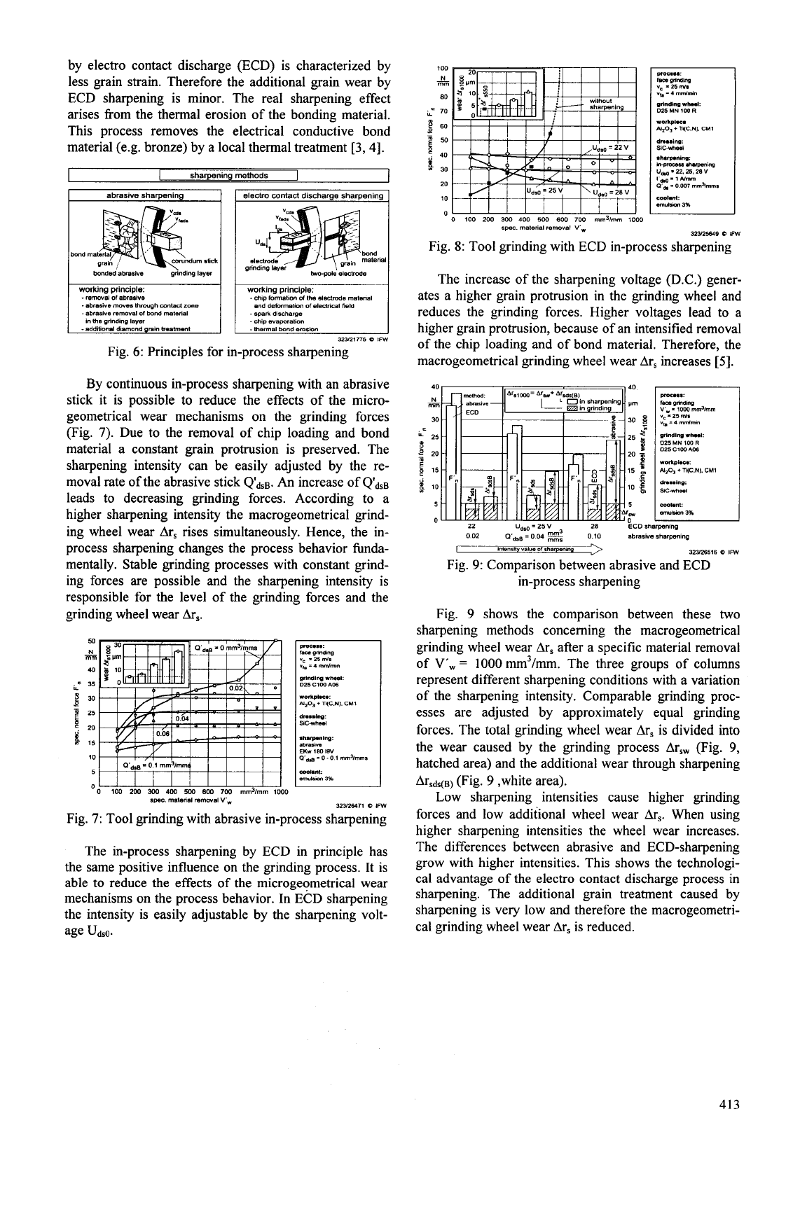
In grinding Ti(C,N) reinforced alumina ceramics the
cutting edge quality can be positively influenced by using
smaller grained grinding wheels (Fig.
3).
The cutting
edge quality is mainly determined by mechanical loads
during grinding. By decreasing the grain size of the
grinding layer, the number of active grains increases by
the square of the grain size reduction. Typically resin
bonded diamond grinding wheels are used for grinding
of
ceramics. The grinding process is heavily depending on
the size of the grains in the grinding layer.
For example due to the reduction of the average grain
size fiom
6
=
41 pm (D46) to
&
=
10 pm
(D10)
about
sixteen times more grains are available
in
the grinding
layer. Because of the higher number of active grains there
is a reduction of mechanical loads in subsurface layers
induced by a single grain
[
1,2].
Fig.
3:
Influence of the diamond grain size on cutting
edge quality
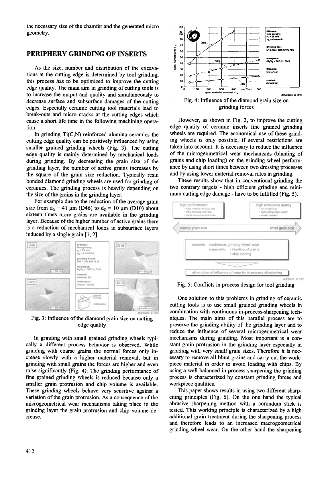
In grinding with small grained grinding wheels typi-
cally
a
different process behavior is observed. While
grinding with coarse grains the normal forces only
in-
crease slowly with a higher material removal, but in
grinding with small grains the forces are higher and even
raise significantly (Fig.
4).
The grinding performance of
fine grained grinding wheels is reduced because only a
smaller grain protrusion and chip volume is available.
These grinding wheels behave very sensitive against a
variation
of
the grain protrusion.
As
a consequence of the
microgeometrical wear mechanisms taking place in the
grinding layer the grain protrusion and chip volume de-
crease.
1W
N
mm
80
c
70
Y
.g
Bo
p
i,
40
20
10
'0
100
2W
300
400
mm3/mm
6W
Fig. 4: Influence of the diamond grain size on
grinding forces
However, as shown in Fig.
3,
to improve the cutting
edge quality of ceramic inserts fine grained grinding
wheels are required. The economical use of these grind-
ing wheels is only possible, if several restrictions are
taken into account. It is necessary to reduce the influence
of the microgeometrical wear mechanisms (blunting of
grains and chip loading) on the grinding wheel perform-
ance by using short times between two dressing processes
and by using lower material removal rates in grinding.
These results show that in conventional grinding the
two contrary targets
-
high efficient grinding and mini-
mum cutting edge damage
-
have to be fidfilled (Fig.
5).
. hlgh
matma1
r-al
rale
.
!cq
dressno
IIIIRV~IIS
. shri
rnngmdhs
hmes
I
reasons: continuous grinding wheel wear
especially:
*
blunting
of
grains
*
chip loading
I,
elimination
of
influence
of
wear by
in-process
sharpening
I
32326514
0
IFW
Fig.
5:
Conflicts in process design for tool grinding
One solution to this problems in grinding of ceramic
cutting tools is to use small grained grinding wheels in
combination with continuous in-process-sharpening tech-
niques. The main aims of this parallel process are to
preserve the grinding ability of the grinding layer and to
reduce the influence of several microgeometrical wear
mechanisms during grinding. Most important is a con-
stant grain protrusion in the grinding layer especially in
grinding with very small grain sizes. Therefore it is nec-
essary to remove all blunt grains and carry out the work-
piece material in order to avoid loading with chips. By
using a well-balanced in-process sharpening the grinding
process is characterized by constant grinding forces and
workpiece qualities.
This paper shows results in using two different sharp-
ening principles (Fig.
6).
On the one hand the typical
abrasive sharpening method with a corundum stick is
tested. This working principle is characterized by a high
additional grain treatment during the sharpening process
and therefore leads to an increased macrogeometrical
grinding wheel wear. On the other hand the sharpening
412
by electro contact discharge (ECD) is characterized by
less grain strain. Therefore the additional grain wear by
ECD sharpening is minor. The real sharpening effect
arises
from
the thermal erosion of the bonding material.
This process removes the electrical conductive bond
material (e.g. bronze) by a local thermal treatment
[3,4].
sharpening methods
I
abrasive sharpening
1
1
electro
wntad
discharge sharpening
I
-
remwsl of
abrasive
.
abrasive
mwes
through
mntecl
z~ns
-
abrasive
remwel
of
bond
mstsriel
-
chip
formalion
of
lhe
el~ctmde
malenal
-spark
discharge
-chip
evaporation
and
def-alion
of
elecvlcal
field
In
me
@ding
layer
zw1m
a
IFW
Fig.
6:
Principles for in-process sharpening
By continuous in-process sharpening with an abrasive
stick it is possible to reduce the effects of the micro-
geometrical wear mechanisms
on
the grinding forces
(Fig.
7).
Due to the removal of chip loading and bond
material a constant grain protrusion is preserved. The
sharpening intensity can be easily adjusted by the re-
moval rate of the abrasive stick QdsB.
An
increase of QdsB
leads to decreasing grinding forces. According to a
higher sharpening intensity the macrogeometrical grind-
ing wheel wear
Ar,
rises simultaneously. Hence, the in-
process sharpening changes the process behavior funda-
mentally. Stable grinding processes with constant grind-
ing forces are possible and the sharpening intensity is
responsible for the level of the grinding forces and the
grinding wheel wear
Ars.
3~512~71
a
IFW
spec.
rnatenal
rem~~al
V',
Fig.
7:
Tool grinding with abrasive in-process sharpening
The in-process sharpening by ECD in principle has
the same positive influence on the grinding process. It is
able to reduce the effects
of
the microgeometrical wear
mechanisms on the process behavior.
In
ECD sharpening
the intensity is easily adjustable by the sharpening volt-
age UdsO.
0
100
200
3M)
400
5W
600
700
mm'lmm
1OM)
325125649
0
IFW
spec.
material
removal
VW
Fig.
8:
Tool grinding with ECD in-process sharpening
The increase of the sharpening voltage (D.C.) gener-
ates a higher grain protrusion
in
the grinding wheel and
reduces the grinding forces. Higher voltages lead to a
higher grain protrusion, because of an intensified removal
of the chip loading and of bond material. Therefore, the
macrogeometrical grinding wheel wear Ars increases
[5].
15
40 40
Irm
30
$
20
s
25
f
10
g
15
f,
5
'n
0
22 28
ECD
sharpening
POC...
:
lam
pmdlng
V'.
-
low
rndlrnrn
vc
-
25
Ws
"*
=
4
rnmrnm
g'lndlng
wh.l:
D25
MN
IW
R
D25
C1W
Affi
W
wfp1.c.
:
Y20,
f
TCN).
CM1
dn..l"p:
SC*rtlal
coOl."t:
*rnYlM
3%
...
0
02
WdSB
=
0
04
0
10
abrarwe
sharpening
__
32326516
0
IFW
hleMh
"Blue
Of
shapnnp
Fig.
9:
Comparison between abrasive and ECD
in-process sharpening
Fig.
9
shows the comparison between these
two
sharpening methods concerning the macrogeometrical
grinding wheel wear Ars after a specific material removal
of
V',
=
1000
mm3/mm. The three groups of columns
represent different sharpening conditions with a variation
of the sharpening intensity. Comparable grinding proc-
esses are adjusted by approximately equal grinding
forces. The total grinding wheel wear
Ars
is
divided into
the wear caused by the grinding process Arsw (Fig.
9,
hatched area) and the additional wear through sharpening
Arsds(B) (Fig.
9
,white area).
Low sharpening intensities cause higher grinding
forces and low additional wheel wear
Ars.
When using
higher sharpening intensities the wheel wear increases.
The differences between abrasive and ECD-sharpening
grow with higher intensities. This shows the technologi-
cal advantage of the electro contact discharge process in
sharpening. The additional grain treatment caused by
sharpening is very low and therefore the macrogeometri-
cal grinding wheel wear Ars is reduced.
413
:=
u
mulslon
3%
o
100
2w
JW
400
mm31mm
600
spec
materid
mmoysi
VW
32~6515
a
IFW
Fig. 10: Potentials of using fine grained grinding wheels
with in-process sharpening
The improvement by in-process sharpening can be re-
alized with different diamond grain sizes of the grinding
wheels. Fig. 10 shows the process behavior of fine
grained grinding wheels with the additional use of ECD
in-process sharpening. It is possible to use diamond grain
sizes down to D10 in efficient grinding processes with
constant forces. This is only possible because the in-
process sharpening preserves a stable level of the grain
protrusion by the removal of bond material and of chip
loading. These results show, that grinding with in-process
sharpening is able to combine high performance grinding
processes and the use of small grained grinding wheels in
order to reach a high cutting edge quality.
PROPERTIES OF THE CUTTING TOOLS
AFTER GRINDING
In tool manufacturing different diamond grain sizes
can be used in grinding.
As
a result of a variation of the
process parameters the contact conditions in grinding can
be changed. The effects of the process parameters on the
contact condition in grinding are characterized by the
average chip thickness
ku.
In face grinding the chip
thickness mainly depends on the four parameters: dia-
mond grain size
6,
diamond concentration C, cutting
speed v, and axial infeed speed vfa
[3].
The influence of
these parameters on the chip thickness is expressed in
formula 1. The chip thickness describes the mechanical
load in the material removal and is predominantly influ-
enced by the diamond grain size.
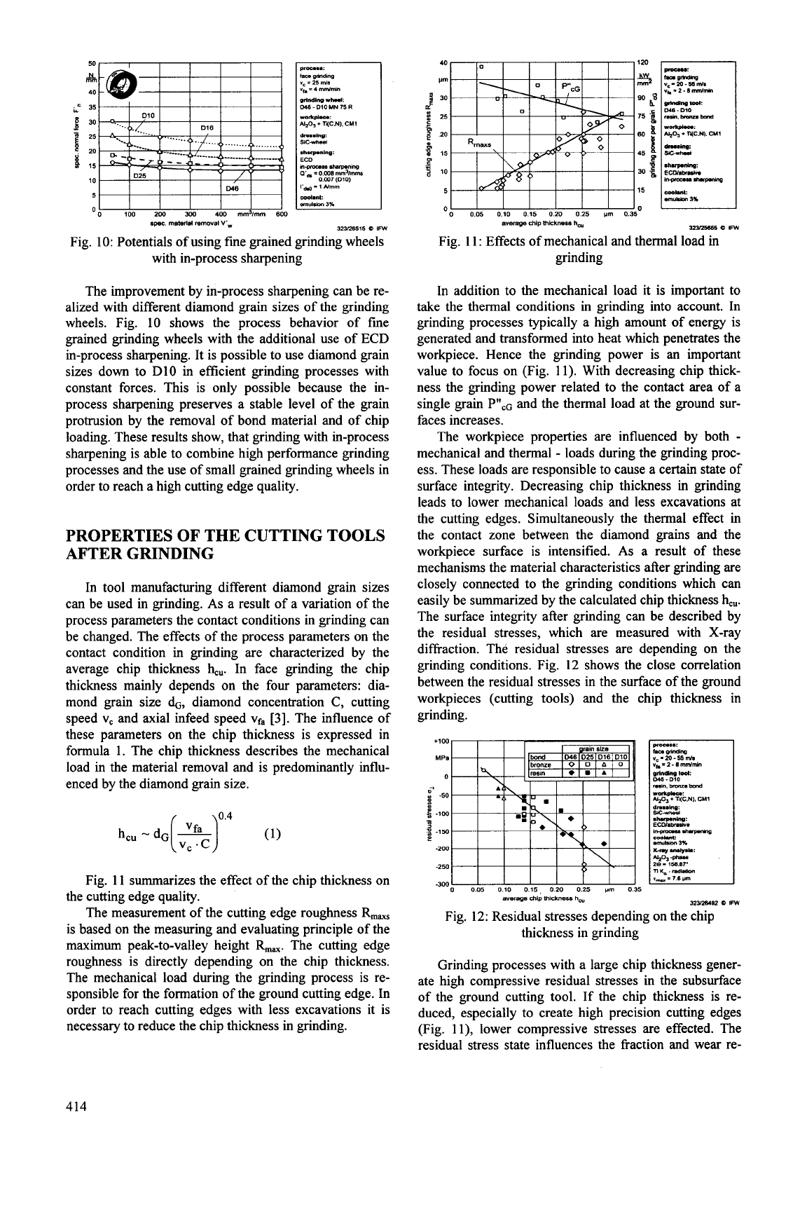
Fig. 11 summarizes the effect of the chip thickness on
The measurement of the cutting edge roughness
the cutting edge quality.
is based on the measuring and evaluating principle of the
maximum peak-to-valley height The cutting edge
roughness is directly depending on the chip thickness.
The mechanical load during the grinding process is re-
sponsible for the formation of the ground cutting edge. In
order to reach cutting edges with less excavations it is
necessary to reduce the chip thickness in grinding.
Ill
o
005
010
015
020
025
wn
0.35
averqe
chip
lhickness
h,
swzw
a
IFW
Fig. 1 1
:
Effects of mechanical and thermal load in
grinding
In addition to the mechanical load it is important to
take the thermal conditions in grinding into account. In
grinding processes typically a high amount of energy
is
generated and transformed into heat which penetrates the
workpiece. Hence the grinding power is an important
value to focus on (Fig. 11). With decreasing chip thick-
ness the grinding power related to the contact area of a
single grain Pll,~ and the thermal load at the ground sur-
faces increases.
The workpiece properties are influenced by both
-
mechanical and thermal
-
loads during the grinding proc-
ess. These loads are responsible to cause a certain state of
surface integrity. Decreasing chip thickness in grinding
leads to lower mechanical loads and less excavations at
the cutting edges. Simultaneously the thermal effect in
the contact zone between the diamond grains and the
workpiece surface is intensified.
As
a result of these
mechanisms the material characteristics after grinding are
closely connected to the grinding conditions which can
easily be summarized by the calculated chip thickness
kU.
The surface integrity after grinding can be described by
the residual stresses, which are measured with X-ray
diffraction. The residual stresses are depending on the
grinding conditions. Fig. 12 shows the close correlation
between the residual stresses in the surface
of
the ground
workpieces (cutting tools) and the chip thickness in
grinding.
+lo0
0
MPB
Yg
-20-55
mh
~~~2-6
m"U&
w
.
DlO
m.bmu.bond
2
a
-50
*cp,
+
I(C.N). CHl
3
-
dwP-Jnv:
5
-1w
.3
150
ihpmu.n*
3-
Ec0I.m.h.
mbm
3%
-200
x.n#
-u:
n&-mmbn
I_
=
1.6
Iml
23%
-250
0
0.05
0.10 0.15,
0
20
0.25
vm
0
35
average
dip
mkhnerr
hw
-300
32Y26482
0
IFW
Fig. 12: Residual stresses depending on the chip
thickness in grinding
Grinding processes with a large chip thickness gener-
ate high compressive residual stresses in the subsurface
of the ground cutting tool. If the chip thickness is re-
duced, especially to create high precision cutting edges
(Fig. ll), lower compressive stresses are effected. The
residual stress state influences the fraction and wear re-
414
sistance of the ground tool flank. The mechanical and
thermal loads of the turning process are responsible for
additional stresses in the cutting tool. The capability of
the cutting tool surface to resist those stresses depends on
the surface integrity after grinding
[6,
7,
81.
In order to examine the significance of the residual
stress state after the tool grinding process, indentation
tests with a Vickers pyramid are carried out. By this
mechanical load a stress state in the subsurface of the
workpiece is generated. The superposition of the residual
stresses caused by grinding and the additional stresses
generated by indentation are responsible for the material
behavior. Fig. 13 shows four different ground surfaces
after similar indentation tests. The surfaces which are
ground with a coarse grained grinding wheel are charac-
terized by high compressive residual stresses and no
failures occur after the indentation test.
-1
Fig. 13: Surface damage after Vickers indentation
(F
=
590
N)
By using fine grained grinding wheels and small chip
thicknesses in grinding tensile residual stresses are cre-
ated in the subsurface of the ground workpiece. The
damages of the ground surface and subsurface is stronger
in grinding with a small chip thickness. These process
conditions lead to a less beneficial surface integrity and
reduce the fraction resistance of the ground surface. Ac-
cording to these properties grinding with a high chip
thickness should be preferred.
The results of the tool grinding process can be sum-
marized as follows. There are
two
main influences of the
grinding process. On the one hand there is the mechanical
influence which is responsible for the created quality of
the cutting edge. In order to reach the continuously in-
creasing demands on the cutting edge quality, it is neces-
sary
to reduce the mechanical treatment of the cutting
edge by decreasing the average chip thickness in grind-
ing. On the other hand the thermal conditions in grinding
have to be taken into account. Improvements in grinding
require a reduction
of
thermal loads to achieve
a
better
surface integrity.
These two directions in the design of tool grinding
processes are contrary. Therefore, it is necessary to in-
vestigate and acquire the best compromise in process
design. In the following an analysis
of
the effects of the
process design in tool grinding on the wear behavior of
Ti(C,N)
reinforced ceramic cutting tools is carried out in
hard turning.
EFFECTS
OF
THE TOOL
GRINDING
PROCESS
ON THE WEAR BEHAVIOR
The main wear mechanisms in hard turning are char-
acterized by the abrasive flank and crater wear. Espe-
cially the width of flank wear land VBc is used as the tool
life criterion. The properties of the tool flank concerning
surface integrity and residual stresses are generated in the
tool grinding process and influenced by the chip thick-
ness
in
grinding. Therefore the effects of the conditions
in grinding on the wear resistance of the tool flank in
hard turning are investigated. Different ground tools are
used in hard turning (Fig.
14).
Typically there are two
phases in the wear behavior of cutting tools in hard
turn-
ing. In the first phase the flank wear suddenly increases
up to values of VBc
=
60
-
80
pm.
This value depends
mainly on the first contact condition between the sharp
cutting edge and the workpiece material. Afterwards the
second wear phase begins. In this phase the flank wear
increases continuously with the cutting length. The
reached tool life depends on the growth of the flank wear
in both phases.
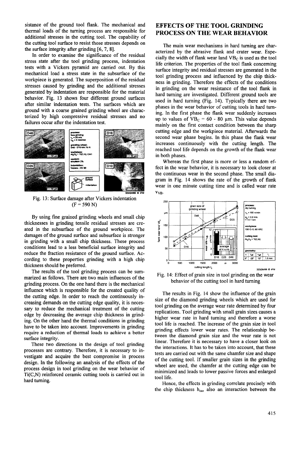
Whereas the first phase is more or less a random ef-
fect in the wear behavior, it is necessary to look closer at
the continuous wear in the second phase. The small dia-
gram in Fig.
14
shows the rate of the growth of flank
wear in one minute cutting time and is called wear rate
VVB.
250,
I I
I
1
I-
0
500
1WO
15W
2wO
m
3000
culling
length
lc
3ZYXd98
0
IFW
Fig. 14: Effect of grain size in tool grinding on the wear
behavior of the cutting tool in hard turning
The results in Fig. 14 show the influence of the grain
size of the diamond grinding wheels which are used for
tool grinding on the average wear rate determined by four
replications. Tool grinding with small grain sizes causes a
higher wear rate in hard turning and therefore a worse
tool life is reached. The increase of the grain size in tool
grinding effects lower wear rates. The relationship be-
tween the diamond grain size and the wear rate
is
not
linear. Therefore it is necessary to have a closer look on
the interactions. It has to be taken into account, that these
tests are carried out with the same chamfer size and shape
of the cutting tool. If smaller grain sizes
in
the grinding
wheel are used, the chamfer at the cutting edge can be
minimized and leads to lower passive forces and enlarged
tool life.
Hence, the effects in grinding correlate precisely with
the chip thickness h,,, also an interaction between the
415
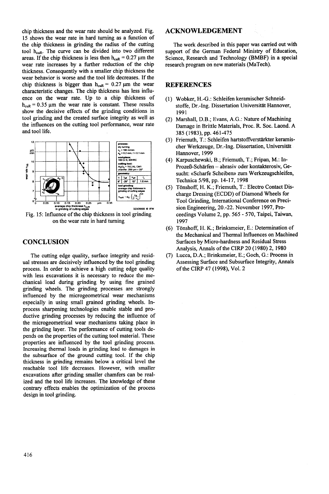
chip thickness and the wear rate should be analyzed. Fig.
15 shows the wear rate in hard turning
as
a hction of
the chip thickness in grinding the radius of the cutting
tool
buR.
The curve can be divided into
two
different
areas. If the chip thickness is less then
buR
=
0.27 pm the
wear rate increases by a Wher reduction of the chip
thickness. Consequently with a smaller chip thickness the
wear behavior is worse and the tool life decreases. If the
chip thickness is bigger than
buR
=
0.27 pm the wear
characteristic changes. The chip thickness has less influ-
ence on the wear rate. Up to a chip thickness of
hcuR
=
0.35 pm the wear rate is constant. These results
show the decisive effects of the grinding conditions in
tool grinding and the created surface integrity as well as
the influences on the cutting tool performance, wear rate
and tool life.
w-ge
dip
mlc*nw
haR
in
grindinp
ofcutl~np
adpss
32?Jzsmo
0
Irn
Fig. 15: Influence of the chip thickness
in
tool grinding
on the wear rate in hard turning
CONCLUSION
The cutting edge quality, surface integrity and resid-
ual stresses are decisively influenced by the tool grinding
process. In order to achieve a high cutting edge quality
with less excavations it is necessary to reduce the me-
chanical load during grinding by using fine grained
grinding wheels. The grinding processes are strongly
influenced by the microgeometrical wear mechanisms
especially in using small grained grinding wheels. In-
process sharpening technologies enable stable and pro-
ductive grinding processes by reducing the influence
of
the microgeometrical wear mechanisms taking place in
the grinding layer. The performance of cutting tools de-
pends on the properties of the cutting tool material. These
properties are influenced by the tool grinding process.
Increasing thermal loads in grinding lead to damages in
the subsurface of the ground cutting tool. If the chip
thickness in grinding remains below a critical level the
reachable tool life decreases. However, with smaller
excavations after grinding smaller chamfers can be real-
ized and the tool life increases. The knowledge of these
contrary effects enables the optimization of the process
design in tool grinding.
ACKNOWLEDGEMENT
The work described in this paper was carried out with
support of the German Federal Ministry of Education,
Science, Research and Technology (BMBF) in a special
research program on new materials (MaTech).
REFERENCES
(1) Wobker, H.-G.: Schleifen keramischer Schneid-
stoffe, Dr.-Ing. Dissertation Universitiit Hannover,
1991
(2) Marshall, D.B.; Evans, A.G.: Nature of Machining
Damage in Brittle Materials, Proc. R. SOC. Laond. A
(3)
Friemuth, T.: Schleifen hartstoffverstiirkter keramis-
385 (1983), pp. 461-475
cher Werkzeuge, Dr.-Ing. Dissertation, Universitiit
Hannover, 1999
ProzeD-Scharfen
-
abrasiv oder kontakterosiv, Ge-
sucht: ((Scharfe Scheibenn zum Werkzeugschleifen,
Technica 5/98, pp. 14-17, 1998
(5)
Tbnshoff,
H.
K.; Friemuth,
T.:
Electro Contact Dis-
charge Dressing (ECDD) of Diamond Wheels for
Tool Grinding, International Conference on Preci-
sion Engineering, 20.-22. November 1997, Pro-
ceedings Volume 2, pp.
565
-
570, Taipei, Taiwan,
1997
(6) Tbnshoff,
H.
K.; Brinksmeier, E.: Determination of
the Mechanical and Thermal Influences on Machined
Surfaces by Micro-hardness and Residual Stress
Analysis, Annals of the CIRP 20 (1980) 2, 1980
(7) Lucca, D.A.; Brinksmeier,
E.;
Goch, G.: Process in
Assessing Surface and Subsurface Integrity, Annals
of the CIRP 47 (1998), Vol. 2
(4) Karpuschewski, B.; Friemuth, T.; Fripan, M.: In-
416
ULTRASONIC ASSISTED FACE GRINDING AND CROSS-PERIPHERAL
GRINDING OF CERAMICS
Eckart Uhlmann and Nikolai-Alexander Daus*
Institute for Machine Tools and Factory Management, TU Berlin, Germany
ABSTRACT
The examples of ultrasonic assisted face grinding
and cross-peripheral grinding demonstrate a possibility
to achieve high material removal rates
in
machining
brittle hard materials, while keeping the workpiece
quality constant. Apart from
an
increase
in
active
speeds, the kinematics lead to constantly altering
nominal engagement angles of the abrasive grains at a
frequencyf;ls
=
20
kHz and
an
amplitude
Ails
of several
micrometers. The material removal and wear mecha-
nisms
of
ultrasonic assisted grinding will be explained
on
the basis of the description of the changing kine-
matic conditions compared to conventional grinding
processes.
INTRODUCTION
An
obstacle to the introduction of functional com-
ponents of brittle hard materials such as advanced ce-
ramics are still the considerable finishing costs. Fin-
ishing is mainly conducted by means of material re-
moving processes with a geometrically undefined
cutting edge, grinding with diamond grain being the
most important among these processes. Complex con-
tours are often manufactured using ultrasonic lapping.
Another possibility for the machining of ceramics is
the technological combination of the processes ultra-
sonic lapping and grinding, creating the hybrid process
ultrasonic assisted grinding.
As early as
1956, bound abrasive grains were used
in ultrasonic assisted machining since the obtainable
machining results
in
ultrasonic lapping are very small
(1).
Up to now, a number of grinding processes has
been superimposed with ultrasonic vibrations. Many
authors agreed that a reduction of process forces leads
to an increase
in
material removal rate (2-7). However,
the influence
on
the surface quality of the workpiece
and on the tool wear is still controversial. Whilst the
range of investigated process variants is rather wide,
the effective correlations leading to an improvement
compared
to
conventional grinding were neglected
in
most cases.
PROCESS VARIANTS
Since the defined transfer of ultrasonic vibrations to
grinding wheels, e.g.
in
surface grinding, is rather diffi-
cult, the ultrasonic vibration is introduced
in
the con-
tact zone by means of a stimulation of the workpiece
in
many process variants.
In
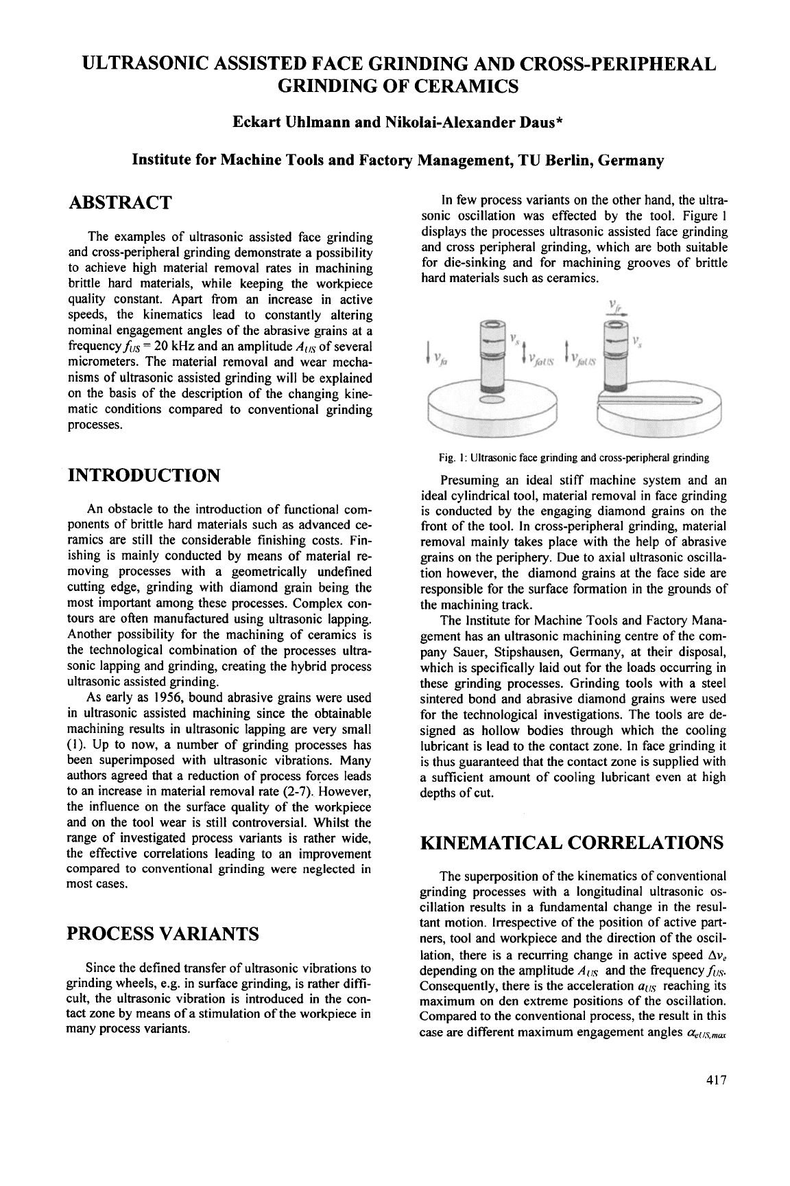
few process variants on the other hand, the ultra-
sonic oscillation was effected by the tool. Figure
1
displays the processes ultrasonic assisted face grinding
and cross peripheral grinding, which are both suitable
for die-sinking and for machining grooves of brittle
hard materials such as ceramics.
Fig.
1:
Ultrasonic face grinding and cross-peripheral grinding
Presuming an ideal stiff machine system and an
ideal cylindrical tool, material removal
in
face grinding
is conducted by the engaging diamond grains
on
the
front of the tool. In cross-peripheral grinding, material
removal mainly takes place with the help of abrasive
grains on the periphery. Due to axial ultrasonic oscilla-
tion however, the diamond grains at the face side are
responsible for the surface formation
in
the grounds of
the machining track.
The Institute for Machine Tools and Factory Mana-
gement has an ultrasonic machining centre of the com-
pany Sauer, Stipshausen, Germany, at their disposal,
which is specifically laid out for the loads occurring
in
these grinding processes. Grinding tools with a steel
sintered bond and abrasive diamond grains were used
for the technological investigations. The tools are de-
signed as hollow bodies through which the cooling
lubricant is lead to the contact zone.
In
face grinding it
is thus guaranteed that the contact zone is supplied with
a sufficient amount of cooling lubricant even at high
depths of cut.
KINEMATICAL CORRELATIONS
The superposition of the kinematics of conventional
grinding processes with a longitudinal ultrasonic
os-
cillation results
in
a fundamental change
in
the resul-
tant motion. Irrespective of the position of active part-
ners, tool and workpiece and the direction of the oscil-
lation, there is a recurring change
in
active speed
Ave
depending on the amplitude
and the frequencyhIs.
Consequently, there is the acceleration
ails
reaching its
maximum
on den extreme positions of the oscillation.
Compared
to
the conventional process, the result
in
this
case are different maximum engagement angles
aell,~,mm
417
on the points of inflection of the oscillation perpen-
dicular to the workpiece surface or different cross
grinding angles
Q,,
parallel to the workpiece surface.
In ultrasonic assisted face grinding the resultant
cutting speed results of the concurrence of the cutting
speed
v,
resulting from the peripheral speed of the tool,
the axial feed speed
vfa
and the axial ultrasonic speed
vfius.
The ultrasonic speed is calculated
as
follows:
vfol/S
=2'A[JS
'Ir*h/S
*sin(2*n'hlS
't)-
(eq*
l)
Figure
2
displays the movement path using the exam-
ple of a diamond grain.
Fig.
2:
Active movement in ultrasonic assisted grinding and engage-
ment angels
If the axial ultrasonic speed runs parallel to the ma-
chined surface, the abrasive grains engage in the form
of a sinus oscillation in the workpiece surface. This
way, the contact between the grain edge and the work-
piece surface is continuously maintained. However,
there is a change
in
cross grinding angles of the en-
gaging diamond grain. This is the case in ultrasonic
assisted cross-peripheral grinding. Compared to con-
ventional grinding, the contact length is much higher.
Figure
3
(left) illustrates such a grinding trace on alu-
minium oxide.
Fig.
3:
Sinusoidal continual engagement in aluminium oxide and
pulsed discontinual engagement in zirconium oxide
With axial oscillation however, the engagement of
diamond grains on the face
is
characterised by
in-
stantaneous local interruptions of the contact between
abrasive grain and workpiece that recur with the work
frequency. If the fracture toughness of the machined
material is sufficiently high, it
is
possible to obtain a
surface structure with trough shaped engagements.
Figure
3
(right) displays a surface produced by ultra-
sonic assisted cross-peripheral grinding of zirconium
oxide. The engagement was effected through diamond
grains on the face of the tool.
The maximum engagement angle or cross grinding
angle, respectively, is the characteristic parameter
for
the motion path resulting from kinematics of ultrasonic
assisted grinding. From the size of this angle it is pos-
sible
to
derive the impact of the ultrasonic oscillation
on the process.
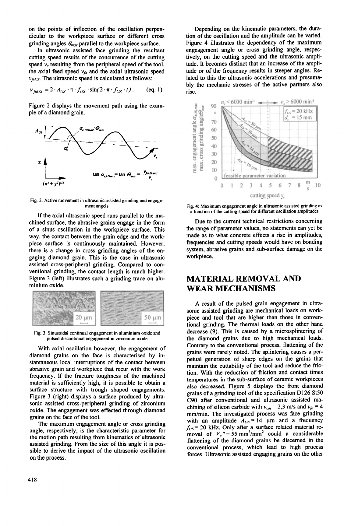
Depending on the kinematic parameters, the dura-
tion
of
the oscillation and the amplitude can be varied.
Figure
4
illustrates the dependency of the maximum
engeagement angle or cross grinding angle, respec-
tively, on the cutting speed and the ultrasonic ampli-
tude. It becomes distinct that an increase of the ampli-
tude or of the frequency results in steeper angles. Re-
lated to this the ultrasonic accelerations and presuma-
bly the mechanic stresses of the active partners also
rise.
0
12
3
4
5
6
7
SYlO
cutting
speed
v,
Fig.
4.
Maximum engagement angle in ultrasonic assisted grinding
as
a function
of
the cutting speed for different oscillation amplitudes
Due to the current technical restrictions concerning
the range of parameter values, no statements can yet be
made
as
to what concrete effects a rise in amplitudes,
frequencies and cutting speeds would have on bonding
system, abrasive grains and sub-surface damage on the
workpiece.
MATERIAL REMOVAL AND
WEAR MECHANISMS
A
result
of
the pulsed grain engagement in ultra-
sonic assisted grinding are mechanical loads on work-
piece and tool that are higher than those
in
conven-
tional grinding. The thermal loads on the other hand
decrease (9). This is caused by a microsplintering
of
the diamond grains due to high mechanical loads.
Contrary to the conventional process, flattening of the
grains were rarely noted. The splintering causes a per-
petual generation of sharp edges on the grains that
maintain the cuttability
of
the tool and reduce the fric-
tion. With the reduction of friction and contact times
temperatures in the sub-surface of ceramic workpieces
also decreased. Figure
5
displays the front diamond
grains of a grinding tool of the specification D126 St50
C90 after conventional and ultrasonic assisted
ma-
chining of silicon carbide with
v,
=
2,3
ds
and
VJ~
7
4
mdmin. The investigated process was face grinding
with an amplitude A(,,s=
14
pm and a frequency
ftIs
=
20
Wz.
Only after a surface related material re-
moval of
v,""
=
55
mm3/mm2 could a considerable
flattening of the diamond grains be discerned in the
conventional process, which lead to high process
forces. Ultrasonic assisted engaging grains on the other
418
hand are characterised by splintered, sharp cutting
edges.
Fig.
5:
Wear on a diamond grain
D46
after conventional (right) and
ultrasonic assisted (left) grinding
In
conventional grinding, bonding material stay be-
hind the abrasive grains. This give additional stability
against chipping to the grain. In ultrasonic assisted
grinding, this process do not appear, the reason being
completely different engagement conditions and higher
engagement angles.
In
accordance with the complete change
in
en-
gagement conditions in ultrasonic assisted grinding, the
removal chips are also significantly different. Figure
6
uses the example of zirconium oxide to illustrate this.
In conventional cross-peripheral grinding, the removed
chips are marked by plastic deformation processes.
Their shape resembles that of conventional removed
chips chips from machining of metals. On the other
hand, the removal particles
in
the ultrasonic assisted
process are smaller in size. Traces of deformation are
hardly discernible. Rapid accelerations and changes of
direction of the tool motion prevent continuous separa-
tion. Low process temperatures and higher engagement
depths resulting from the oscillation reduce the affinity
for plastic deformation.
Fig.
6:
Zirconium oxide removal chips after ultrasonic (left) and
conventional (right) cross-peripheral grinding
The mechanical loads which are concluded from
the wear behaviour of the tools lead to a change of
properties even in the sub-surface of the workpieces.
In
the case of surface grinding with axial oscillation it was
concluded that there are no disadvantages arising for
the residual stresses and strength characteristics
(8).
After comparing ultrasonic assisted cross-peripheral
grinding with plane parallel lapped ceramic work-
pieces, the conclusion was confirmed
(9).
TECHNOLOGICAL INVESTIGA-
TION
The focal point of the technological investigations
was the machining of advanced ceramics and glass by
ultrasonic assisted face grinding and cross-peripheral
grinding.
It
was investigated to what extent the obtain-
able material removal rates can be increased by ultra-
sonic assisted of the grinding process. Subject of the
investigations was further the question what effect the
increased mechanical loads and the high frequency
oscillation have on the surface formation and the prop-
erties of the machined component.
The process forces were measured with a force
measuring system by the company Kistler.
A
subse-
quent evaluation software was applied to analyse the
values. Since the frequency of the oscillation of
fils
=
20
kHz is very high, a dynamic force measurement was
not conducted. Therefore, the force values given below
represent a mean stationary value.
Concerning economic efficiency, it was ascertained
that it is possible to considerably increase the material
removal rates compared to former prototypical instal-
lations. This is especially the case
in
ultrasonic assisted
face grinding, in which the integrated flushing box
permits the supply of cooling lubricant and the trans-
port of removed particles from the contact zone even at
higher depths of cut.
In
contrast to results gained
in
previous investigations, there was no above-average
increase
in
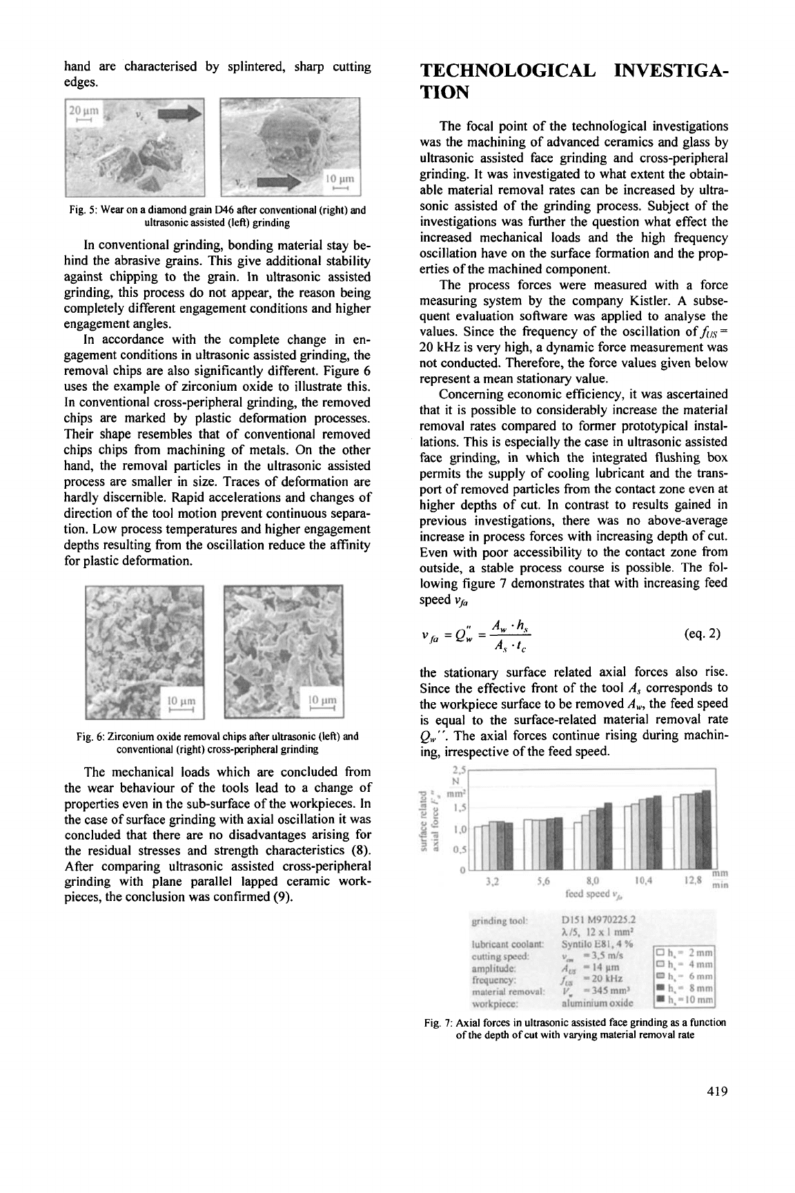
process forces with increasing depth of cut.
Even with poor accessibility to the contact zone from
outside, a stable process course is possible. The fol-
lowing figure
7
demonstrates that with increasing feed
speed
vJ~
the stationary surface related axial forces also rise.
Since the effective front of the tool
A,$
corresponds to
the workpiece surface to be removed
A,,
the feed speed
is equal to the surface-related material removal rate
Q,"".
The axial forces continue rising during machin-
ing, irrespective of the feed speed.
Y
3,2
5.6
8.0
10.4
feed
speed
v,*
Fig.
7:
Axial forces in ultrasonic assisted face grinding
as
a function
of the depth of cut with varying material removal rate
419
8
4
ipN
t
8
--
3
mm*
U
a
s
-
L:
w
0
"
0
5
10
15
20
mm'min
Em..
30
sufm
related material removal
rate
Q",
I
I
I
1
workpi
1
I
t
I
IT7
+
t
t
2fl
0
-:
-*
4
ill
i
1
1
I
1
I
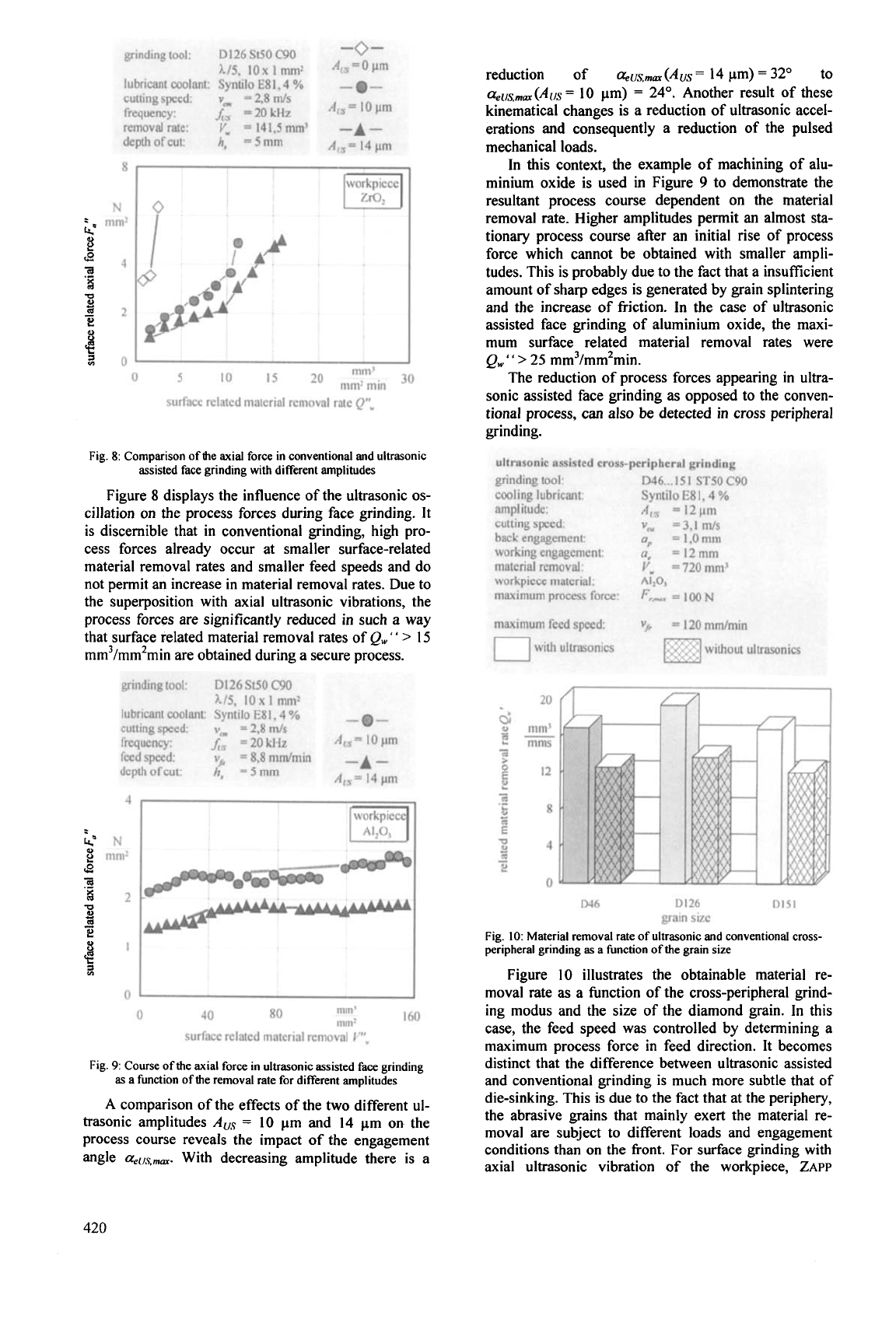
Fig.
8:
Comparison
of
the axial force in conventional and ultrasonic
assisted face grinding with different amplitudes
Figure
8
displays the influence of the ultrasonic
os-
cillation on the process forces during face grinding. It
is discernible that in conventional grinding, high pro-
cess forces already occur at smaller surface-related
material removal rates and smaller feed speeds and do
not permit an increase
in
material removal rates. Due to
the superposition with axial ultrasonic vibrations, the
process forces are significantly reduced
in
such a way
that surface related material removal rates of
Q,"
' '
>
15
mm3/mm2min are obtained during a secure process.
reduction of
Q~US.,,~
(AUS
=
14
pm)
=
32"
to
G~/~,~~
(A(,S
=
10
pm)
=
24".
Another result of these
kinematical changes is a reduction
of
ultrasonic accel-
erations and consequently a reduction of the pulsed
mechanical loads.
In this context, the example
of
machining of alu-
minium oxide is used in Figure
9
to demonstrate the
resultant process course dependent on the material
removal rate. Higher amplitudes permit
an
almost
sta-
tionary process course after
an
initial rise of process
force which cannot be obtained with smaller ampli-
tudes. This is probably due to the fact that a insufficient
amount of sharp edges is generated by grain splintering
and the increase of frjction. In the case of ultrasonic
assisted face grinding of aluminium oxide, the maxi-
mum surface related material removal rates were
Qw
"
>
25
mm3/mm2min.
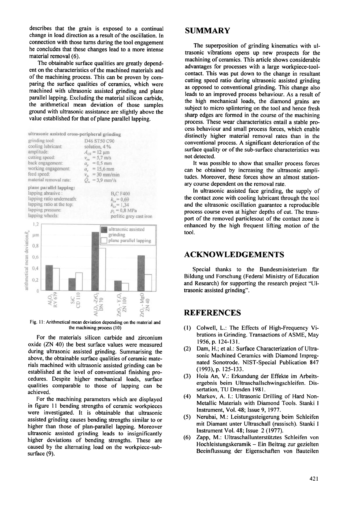
The reduction of process forces appearing in ultra-
sonic assisted face grinding as opposed to the conven-
tional process, can also
be
detected
in
cross peripheral
grinding.
046
D126
D151
grain
size
Fig.
10:
Material removal rate
of
ultrasonic and conventional cross-
peripheral grinding
as
a function
of
the grain size
Figure
10
illustrates the obtainable material re-
moval rate
as
a function of the cross-peripheral grind-
ing modus and the size
of
the diamond grain.
In
this
case, the feed speed was controlled by determining a
maximum process force in feed direction. It becomes
distinct that the difference between ultrasonic assisted
and conventional grinding is much more subtle that of
die-sinking. This is due to the fact that at the periphery,
the abrasive grains that mainly exert the material re-
moval are subject to different loads and engagement
conditions than on the front. For surface grinding with
axial ultrasonic vibration
of
the workpiece,
ZAPP
420
describes that the grain is exposed to a continual
change in load direction as a result of the oscillation.
In
connection with those turns during the tool engagement
he concludes that these changes lead to a more intense
material removal
(6).
The obtainable surface qualities are greatly depend-
ent on the characteristics of the machined materials and
of the machining process. This can be proven by com-
paring the surface qualities of ceramics, which were
machined with ultrasonic assisted grinding and plane
parallel lapping. Excluding the material silicon carbide,
the arithmetical mean deviation of those samples
ground with ultrasonic assistance are slightly above the
value established for that of plane parallel lapping.
t
iron
ultrasonic assisted
grinding
plane parallel lapping
12
I
Fig.
11:
Arithmetical mean deviation depending on the material and
the machining process
(10)
For the materials silicon carbide and zirconium
oxide (ZN
40) the best surface values were measured
during ultrasonic assisted grinding. Summarising the
above, the obtainable surface qualities of ceramic mate-
rials machined with ultrasonic assisted grinding can be
established at the level of conventional finishing pro-
cedures. Despite higher mechanical loads, surface
qualities comparable
to
those
of
lapping can be
achieved.
For the machining parameters which are displayed
in figure
11
bending strengths of ceramic workpieces
were investigated. It is obtainable that ultrasonic
assisted grinding causes bending strengths similar to or
higher than those of plan-parallel lapping. Moreover
ultrasonic assisted grinding leads to insignificantly
higher deviations of bending strengths. These are
caused by the alternating load on the workpiece-sub-
surface
(9).
SUMMARY
The superposition of grinding kinematics with ul-
trasonic vibrations opens up new prospects for the
machining of ceramics. This article shows considerable
advantages for processes with a large workpiece-tool-
contact. This was put down to the change
in
resultant
cutting speed ratio during ultrasonic assisted grinding
as
opposed to conventional grinding. This change also
leads to an improved process behaviour. As a result of
the high mechanical loads, the diamond grains are
subject to micro splintering on the tool and hence fresh
sharp edges are formed in the course of the machining
process. These wear characteristics entail a stable pro-
cess behaviour and small process forces, which enable
distinctly higher material removal rates than
in
the
conventional process.
A
significant deterioration of the
surface quality or of the sub-surface characteristics was
not detected.
It was possible to show that smaller process forces
can be obtained by increasing the ultrasonic ampli-
tudes. Moreover, these forces show an almost station-
ary course dependent on the removal rate.
In
ultrasonic assisted face grinding, the supply of
the contact zone with cooling lubricant through the tool
and the ultrasonic oscillation guarantee a reproducible
process course even at higher depths of cut. The trans-
port of the removed particlesout of the contact zone is
enhanced by the high frequent lifting motion of the
tool.
ACKNOWLEDGEMENTS
Special thanks to the Bundesministerium fir
Bildung und Forschung (Federal Ministry of Education
and Research) for supporting the research project
"Ul-
trasonic assisted grinding".
REFERENCES
Colwell,
L.:
The Effects of High-Frequency Vi-
brations
in
Grinding. Transactions of ASME, May
Dam, H.; et al.: Surface Characterization of Ultra-
sonic Machined Ceramics with Diamond Impreg-
nated Sonotrode. NIST-Special Publication
847
Hoia An, V.: Erkundung der Effekte
im
Arbeits-
ergebnis beim
Ultraschallschwingschleifen. Dis-
sertation, TU Dresden
198
1.
Markov, A. I.: Ultrasonic Drilling of Hard Non-
Metallic Materials with Diamond
Tools.
Stanki
I
Instrument, Vol. 48; Issue 9, 1977.
Nerubai, M.: Leistungssteigerung beim Schleifen
mit Diamant unter Ultraschall (russisch). Stanki
I
Instrument Vol. 48; Issue
2
(1
977).
Zapp,
M.:
Ultraschallunterstutztes
Schleifen von
Hochleistungskeramik
-
Ein Beitrag zur gezielten
Beeinflussung der Eigenschaften von Bauteilen
1956,
p. 124-131.
(1993),
p. 125-133.
42
1