Heinrich J.G., Aldinger F. (Eds.) Ceramic Materials and Components for Engines
Подождите немного. Документ загружается.

a. Maximum stresses for start-stopp-events
(N
=
3
.
lo4
Occuring
local
Transformed Local endurable
Stress [MPal tude
a,
[MPa] tude
asE
[MPa]
a,,,*
aa
(R=O)
(R=O, Ps=50%)
pas,
equivalent
stress
ampli-
stress
ampli-
el +70.3
f
70.3 70.3 188
e2
+8.5
f5.6 12.0 188
e3
+71.6f 71.6 71.6
I88
Safe&
j'=a,/o,
(R=o)
2.7
15.7
2.6
._
e4
e5
eh
~~ ~
-1
15.6
f
274.8 79.6 188 2.4
+6.8
f
13.9 10.3 188 18.2
+44.1
f
44.1 44.1 188 4.3
b.
Maximum stresses during operation
(N
=
2
.
lo9
__
e7
e8
e9
el0
..
+37.5
f
37.5 37.5 188
5.0
+68.1
f
70.0 69.1 188 2.7
+63.7
f
63.1 63.1 188 2.9
-60.0
f
60.0
0
I88
Q)
e9
I
+63.8
f
63.6
I
63.7
I
170
I
2.7
el0
1
-60.0
f
60.0
I
0
I
I70
I
Q)
e6
e7
e8
Tab.
4
Evaluation of calculated occuring stresses on a
Si,N,-exhaust valve
+47.3
f
40.9
43.0 170 3.9
+37.6
f
34.5 36.5 I70 4.6
+69.1
f
69.1 69.
I
170 2.5
Using the slopes
of
the mean-stress-amplitude diagrams
all stress combinations are transferred to the stress ratio
R
=
0.
All ratios j* between endurable and occuring
stress amplitudes exceed the minimum safety margin
j,
=
1.98 for the failure probability
Pf
=
10'.
This means
for the most critical point
Pf<
lo-'.
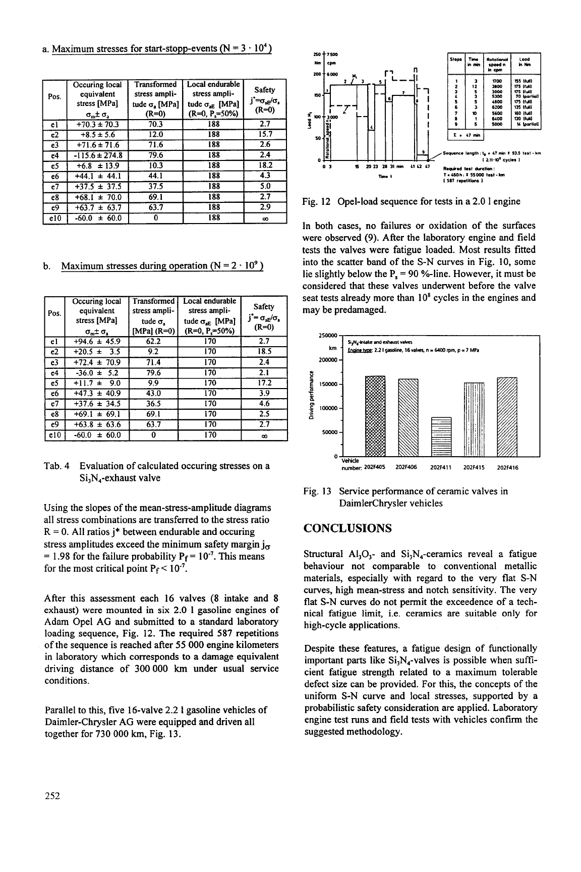
After this assessment each 16 valves (8 intake and 8
exhaust) were mounted in six
2.0
1
gasoline engines of
Adam Ope1 AG and submitted to a standard laboratory
loading sequence, Fig.
12.
The required
587
repetitions
of the sequence is reached after
55
000
engine kilometers
in laboratory which corresponds to a damage equivalent
driving distance of
300
000
km
under usual service
conditions.
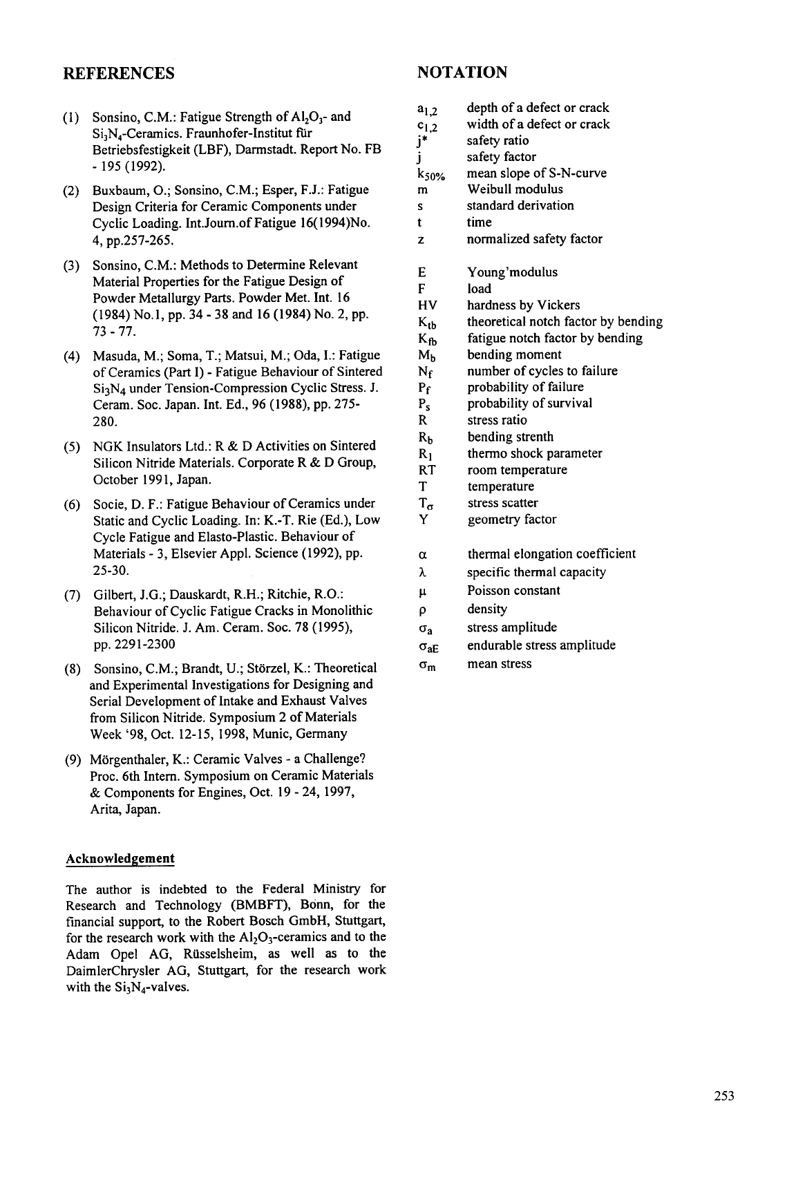
Parallel to this, five 16-valve
2.2
I
gasoline vehicles of
Daimler-Chrysler AG were equipped and driven all
together for
730
000
km,
Fig.
13.
p
7m
95
I.
17-
Fig.
12
Opel-load sequence for tests in a
2.0
1
engine
In both cases, no failures
or
oxidation of the surfaces
were observed (9). After the laboratory engine and field
tests the valves were fatigue loaded. Most results fitted
into the scatter band of the S-N curves in Fig.
10,
some
lie slightly below the P,
=
90
%-line. However, it must be
considered that these valves underwent before the valve
seat tests already more than
10'
cycles
in
the engines and
may be predamaged.
-
Vehicle
number:
202F405
202F406
202F411 202F415
202F416
Fig. 13 Service performance of ceramic valves
in
DaimlerChrysler vehicles
CONCLUSIONS
Structural AI,O,- and Si,N,-ceramics reveal a fatigue
behaviour not comparable to conventional metallic
materials, especially with regard to the very flat S-N
curves, high mean-stress and notch sensitivity. The very
flat S-N curves do not permit the exceedence of a tech-
nical fatigue limit, i.e. ceramics are suitable only for
high-cycle applications.
Despite these features, a fatigue design of functionally
important parts like Si,N4-valves is possible when suffi-
cient fatigue strength related to a maximum tolerable
defect size can be provided. For this, the concepts of the
uniform
S-N
curve and local stresses, supported by a
probabilistic safety consideration are applied. Laboratory
engine test runs and field tests with vehicles confirm the
suggested methodology.
252
REFERENCES
NOTATION
Sonsino, C.M.: Fatigue Strength of AI,O,- and
Si,N,-Ceramics. Fraunhofer-Institut
fir
Betriebsfestigkeit (LBF), Darmstadt. Report No. FB
Buxbaum,
0.;
Sonsino, C.M.; Esper, F.J.: Fatigue
Design Criteria for Ceramic Components under
Cyclic Loading. 1nt.Journ.of Fatigue l6( 1994)No.
Sonsino, C.M.: Methods to Determine Relevant
Material Properties for the Fatigue Design of
Powder Metallurgy Parts. Powder Met. Int. 16
(1984)
No.1, pp. 34
-
38 and 16 (1984)No. 2, pp.
73
-
77.
Masuda, M.; Soma, T.; Matsui, M.; Oda,
I.:
Fatigue
of Ceramics (Part
I)
-
Fatigue Behaviour of Sintered
Si3N4 under Tension-Compression Cyclic Stress.
J.
Ceram. SOC. Japan. Int. Ed., 96 (1988), pp. 275-
280.
NGK
Insulators Ltd.: R
&
D Activities on Sintered
Silicon Nitride Materials. Corporate R
&
D Group,
October 199 1
,
Japan.
Socie, D. F.: Fatigue Behaviour of Ceramics under
Static and Cyclic Loading. In: K.-T. Rie (Ed.), Low
Cycle Fatigue and Elasto-Plastic. Behaviour of
Materials
-
3, Elsevier Appl. Science (1992), pp.
Gilbert, J.G.; Dauskardt, R.H.; Ritchie, R.O.:
Behaviour of Cyclic Fatigue Cracks in Monolithic
Silicon Nitride. J. Am. Ceram. SOC. 78 (1999,
Sonsino, C.M.; Brandt,
U.;
Storzel,
K.:
Theoretical
and Experimental Investigations for Designing and
Serial Development of Intake and Exhaust Valves
from Silicon Nitride. Symposium 2 of Materials
Week ‘98, Oct. 12-15, 1998, Munic, Germany
Morgenthaler, K.: Ceramic Valves
-
a Challenge?
Proc. 6th Intern. Symposium on Ceramic Materials
&
Components for Engines, Oct. 19
-
24, 1997,
Arita, Japan.
-
195 (1992).
4,
pp.257-265.
25-30.
pp. 2291-2300
Acknowledgement
The author
is
indebted to the Federal Ministry for
Research and Technology (BMBFT), Bonn, for the
financial support, to the Robert Bosch GmbH, Stuttgart,
for the research work with the A1203-ceramics and to the
Adam Ope1 AG, Riisselsheim, as well
as
to the
DaimlerChrysler AG, Stuttgart, for the research
work
with the Si3N4-valves.
depth of a defect
or
crack
width of a defect
or
crack
safety ratio
safety factor
mean slope of S-N-curve
Weibull modulus
standard derivation
time
normalized safety factor
Young’modulus
load
hardness by Vickers
theoretical notch factor by bending
fatigue notch factor by bending
bending moment
number of cycles to failure
probability of failure
probability of survival
stress ratio
bending strenth
thermo shock parameter
room temperature
temperature
stress scatter
geometry factor
thermal elongation coefficient
specific thermal capacity
Poisson constant
density
stress amplitude
endurable stress amplitude
mean stress
253

This Page Intentionally Left Blank
DESIGN AND TESTING OF A PROTOTYPE
SiSiC HEAT EXCHANGER FOR COAL COMBUSTION POWER STATIONS
H. R. Maier",
K.
Himmelstein
Rheinisch-Westfalische Technische Hochschule (RWTH) Aachen, Germany
ABSTRACT
The presented paper relates to a national founded
project (BMWi) which is concerned with the design and
testing of a ceramic high temperature heat exchanger for
coal fired power stations (PPCCCC-process). The
project is carried out in cooperation with the Institut
fiir
Warme- und Brennstofftechnik (IWBT) of the
University of Braunschweig and four industrial partners.
The Institut fir Keramische Komponenten im
Maschinenbau of the RWTH Aachen
(IKKM)
is
engaged with the concept approach, computer aided
design, with material characterisations and prototype
testing. In parallel the IKKM is involved in a European
project refemng to the design of
a
heat exchanger for an
alternative coal fired cycle (EFCC-process). The main
features are compared with emphasis on the PPCCCC-
process.
1.
INTRODUCTION
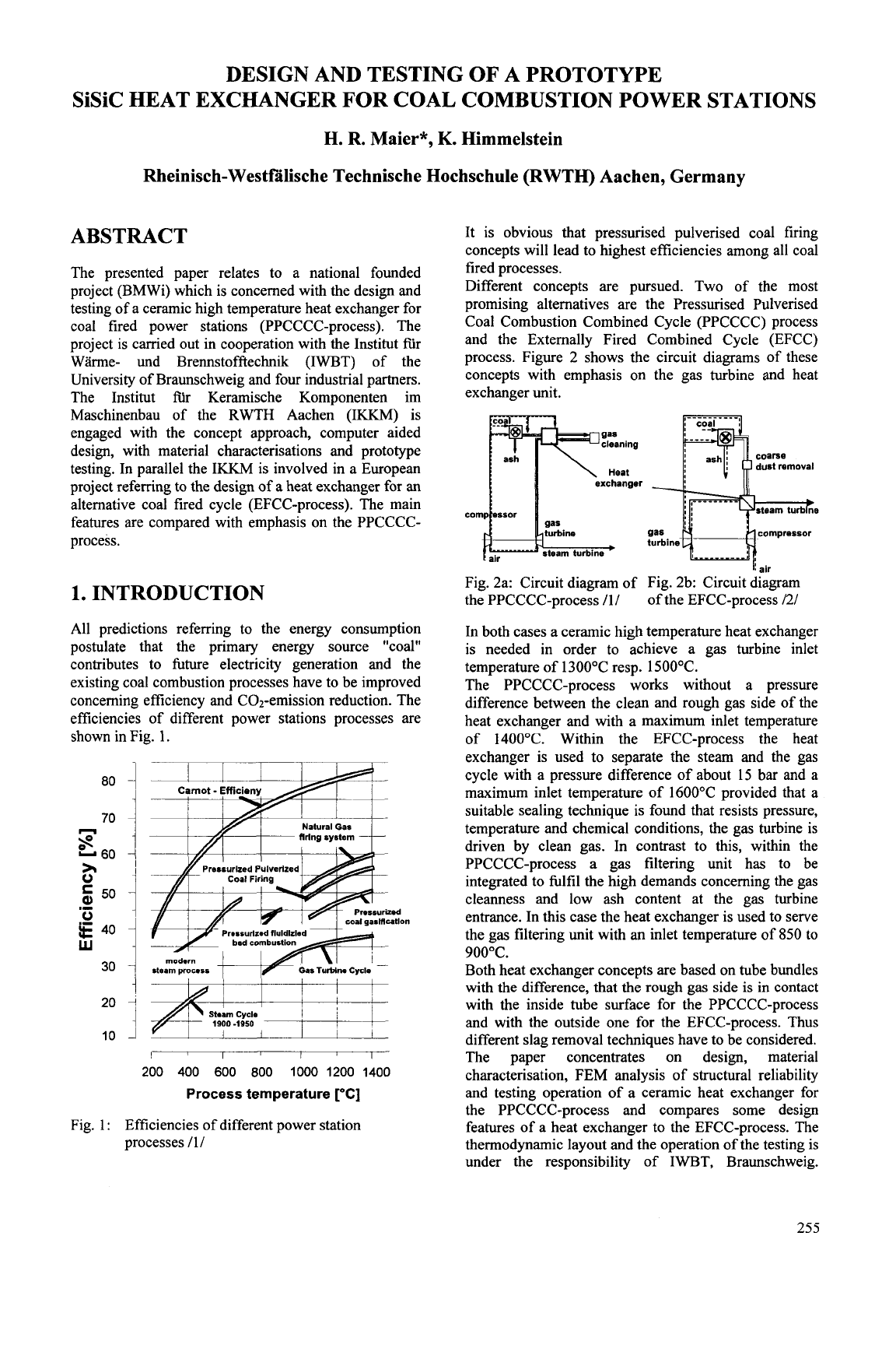
All predictions referring to the energy consumption
postulate that the primary energy source "coal"
contributes to hture electricity generation and the
existing coal combustion processes have to be improved
concerning efficiency and COz-emission reduction. The
efficiencies of different power stations processes are
shown
in
Fig.
1.
I
I
I
I
I
I
1
St*M
Cycle
1900
-1950
I
I
1
I
Fig.
1:
I I I I
200
400
600
800
1000
1200
1400
Process temperature
YC]
Efficiencies of different power station
processes /1/
It is obvious that pressurised pulverised coal firing
concepts will lead to highest efficiencies among all coal
fired processes.
Different concepts are pursued. Two of the most
promising alternatives are the Pressurised Pulverised
Coal Combustion Combined Cycle (PPCCCC) process
and the Externally Fired Combined Cycle (EFCC)
process. Figure
2
shows the circuit diagrams of these
concepts with emphasis on the gas turbine and heat
exchanger unit.
compressor
turbine
Fig. 2a: Circuit diagram of Fig. 2b: Circuit diagram
the PPCCCC-process /1/ of the EFCC-process
/2/
In both cases a ceramic high temperature heat exchanger
is needed in order to achieve a gas turbine inlet
temperature of 1300°C resp. 1500°C.
The PPCCCC-process works without a pressure
difference between the clean and rough gas side of the
heat exchanger and with a maximum inlet temperature
of 1400°C. Within the EFCC-process the heat
exchanger is used to separate the steam and the gas
cycle with a pressure difference of about 15 bar and a
maximum inlet temperature of 1600°C provided that a
suitable sealing technique is found that resists pressure,
temperature and chemical conditions, the gas turbine is
driven by clean gas. In contrast to this, within the
PPCCCC-process a gas filtering unit has to be
integrated to fulfil the high demands concerning the gas
cleanness and low ash content at the gas turbine
entrance. In this case the heat exchanger is used to serve
the gas filtering unit with an inlet temperature of
850
to
900°C.
Both heat exchanger concepts are based on tube bundles
with the difference, that the rough gas side
is
in contact
with the inside tube surface for the PPCCCC-process
and with the outside one for the EFCC-process. Thus
different slag removal techniques have to be considered.
The paper concentrates on design, material
characterisation, FEM analysis of structural reliability
and testing operation of a ceramic heat exchanger for
the PPCCCC-process and compares some design
features of a heat exchanger to the EFCC-process. The
thermodynamic layout and the operation of the testing is
under the responsibility
of
IWBT, Braunschweig.
255
Economical aspects such
as
heat exchanger surface,
volume weight and costs per kW electrical power output
considered seperately
.
2.
DESIGN
OF
THE HEAT
EXCHANGER UNIT
compressed
air
Is
L
The design process of the heat exchanger follows the
IKKM guidelines referring to the design management,
shown in Fig. 3.
The overlapping design phases are impacted by a bundle
of alternatives and each measure taken has to be
carefully evaluated for its interactions. In addition it has
to be taken into account, that each ceramic component,
module
or
functional unit is linked to its ceramic
or
non
ceramic environment by
-
force flow,
-
heat flow and
-
mass flow
which is illustrated in Fig. 4.
Fig. 3: Design Phases and impacts 13/
On a macro scale the mass flow includes the rough and
clean gas side, the leakage between them and the
environment and on a micro scale chemical reactions
and difision transport mechanisms. Special attention
has to be paid to the fact that constrained thermal
expansions due to heat flow can be turned into risky
changes in force flow and stress distribution.
Fig. 4: Functional unit 131
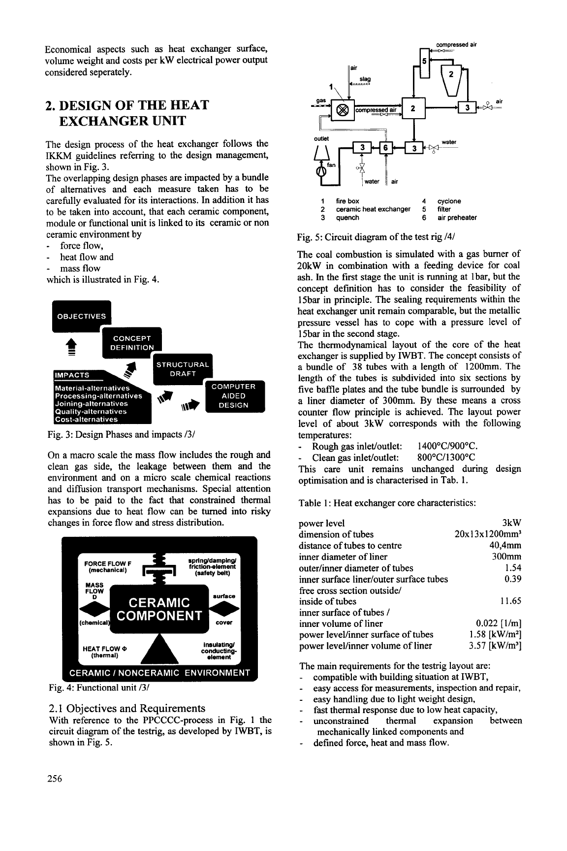
2.1
Objectives and Requirements
With reference to the PPCCCC-process in Fig. 1 the
circuit diagram of the testrig,
as
developed by IWBT, is
shown in Fig. 5.
water
1
fire
box
4
cyclone
2
ceramic heat exchanger
5
filter
3
quench
6
air preheater
Fig. 5: Circuit diagram of the test rig I41
The coal combustion is simulated with a gas burner of
20kW in combination with a feeding device for coal
ash. In the first stage the unit is running at lbar, but the
concept definition has to consider the feasibility of
15bar in principle. The sealing requirements within the
heat exchanger unit remain comparable, but the metallic
pressure vessel has to cope with a pressure level of
1 Sbar in the second stage.
The thermodynamical layout of the core of the heat
exchanger is supplied by IWBT. The concept consists of
a bundle of
38
tubes with a length of 1200mm. The
length of the tubes is subdivided into six sections by
five baffle plates and the tube bundle is surrounded by
a liner diameter of 300mm. By these means a cross
counter flow principle is achieved. The layout power
level of about 3kW corresponds with the following
temperatures:
-
Rough gas inletfoutlet: 1400"C1900"C.
-
Clean gas inletfoutlet: 80O"Cll 300°C
This care unit remains unchanged during design
optimisation and is characterised in Tab. 1.
Table
1
:
Heat exchanger core characteristics:
power level
dimension of tubes
distance of tubes to centre
inner diameter of liner
outerlinner diameter of tubes
inner surface linedouter surface tubes
free cross section outside1
inside of tubes
inner surface of tubes
I
inner volume of liner
power levellinner surface of tubes
power levelfinner volume of liner
3kW
20x13x1200mm3
40,4mm
300mm
1.54
0.39
11.65
0.022 [llm]
1.58 [kWlm2]
3.57 [kW/m3]
The main reauirements for the testrig layout are:
compatibie with building situation at IWBT,
easy access for measurements, inspection and repair,
easy handling due to light weight design,
fast thermal response due to low heat capacity,
unconstrained thermal expansion between
defined force, heat and mass flow.
mechanically linked components and
256
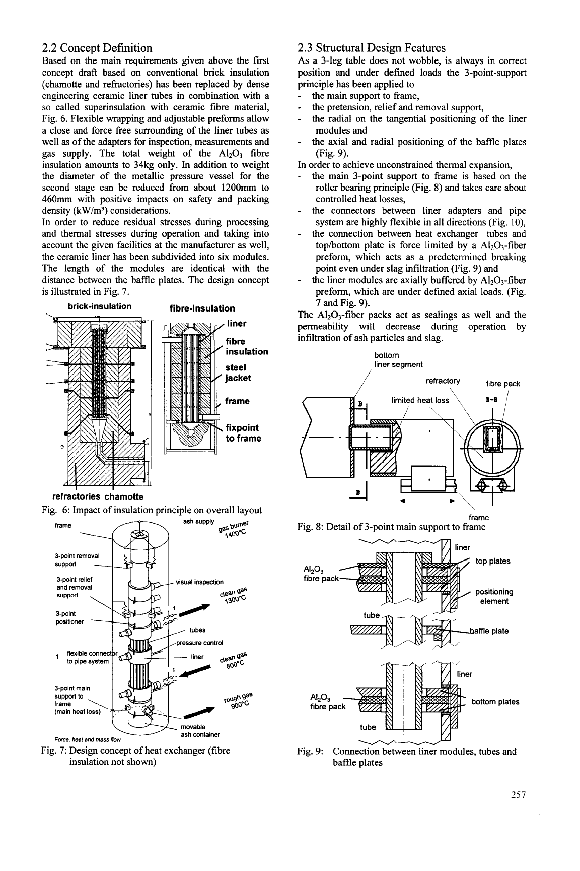
2.2
Concept Definition
Based on the main requirements given above the first
concept draft based on conventional brick insulation
(chamotte and refractories) has been replaced by dense
engineering ceramic liner tubes in combination with a
so
called superinsulation with ceramic fibre material,
Fig.
6.
Flexible wrapping and adjustable preforms allow
a close and force free surrounding of the liner tubes
as
well
as
of the adapters for inspection, measurements and
gas supply. The total weight of the A1203 fibre
insulation amounts to 34kg only. In addition to weight
the diameter of the metallic pressure vessel for the
second stage can be reduced from about 1200mm to
460mm with positive impacts on safety and packing
density (kW/m3) considerations.
In order to reduce residual stresses during processing
and thermal stresses during operation and taking into
account the given facilities at the manufacturer
as
well,
the ceramic liner has been subdivided into six modules.
The length of the modules are identical with the
distance between the baMe plates. The design concept
is illustrated in Fig.
7.
brick-insulation fibre-insulation
liner
fibre
insulation
steel
jacket
frame
fixpoint
to frame
refractories charnotte
Fig.
6:
Impact of insulation principle on overall layout
movable
ash container
Force. heat and
mass
flow
Fig.
7:
Design concept of heat exchanger (fibre
insulation not shown)
2.3 Structural Design Features
As a 3-leg table does not wobble, is always in correct
position and under defined loads the 3-point-support
principle has been applied to
-
-
-
the main support to frame,
the pretension, relief and removal support,
the radial on the tangential positioning of the liner
the axial and radial positioning of the baffle plates
modules and
(Fig.
9).
-
In order to achieve unconstrained thermal expansion,
-
the main 3-point support to frame is based on the
roller bearing principle (Fig.
8)
and takes care about
controlled heat losses,
-
the connectors between liner adapters and pipe
system are highly flexible in all directions (Fig. lo),
-
the connection between heat exchanger tubes and
tophottom plate is force limited by a AI2O3-fiber
preform, which acts as a predetermined breaking
point even under slag infiltration (Fig.
9)
and
the liner modules are axially buffered by A1203-fiber
preform, which are under defined axial loads. (Fig.
7
and Fig.
9).
The A1203-fiber packs act as sealings as well and the
permeability will decrease during operation by
infiltration of ash particles and slag.
-
bottom
liner segment
fibre pack
-
frame
Fig.
8:
Detail
of
3-point main support to frame
Y
liner
fibre pack
pressure control
AP,
fibre pac
YA
tube
I
-
Fig.
9:
Connection between liner modules, tubes and
baMe plates
257
high temperature
A@,
sleeve allows axial and radial fibre
pa&
SOz,
02,
14OO0C, 12h
HCI,
Nz,
1400"C, 12h
HCI.
Nz,
02,1400"C, 12h
Pre-oxidized,
1200°C. 200h
I----
143 130
397 3,7
244 226
458 5-4
252 242 325 10,6
gap forseen for
different thermal expansions
Fig. 10: Flexible connector (detail of 1 of Fig. 10)
2.4
Computer Aided Design
will follow after material processing and joining
alternatives.
3.
MATERIAL ALTERNATIVES
AND CHARACTERISATION
Based on the manufacturing capacity of the industrial
partner involved, the ceramic alternatives
-
Siliconnitride bonded Siliconcarbide (NSiC),
-
Recrystallised Siliconcarbide (RSiC) and
-
Silicon infiltrated Siliconcarbide (SiSiC, Si: 20%)
have been taken into account.
The most promising candidate has been preselected by
slag wetting tests with three different hard coal ashes
and one brown coal ash. The depth of infiltration and
the amount of the corrosion products were determined
by Scanning-Electron-Microscopy-analysis. This
analysis showed that lignite coal ash is more corrosive
to all materials candidates than hard coal ash and that
SiSiC demonstrates the best corrosion behaviour against
the different coal ashes. NSiC is positioned at the end
of
the ranking tail.
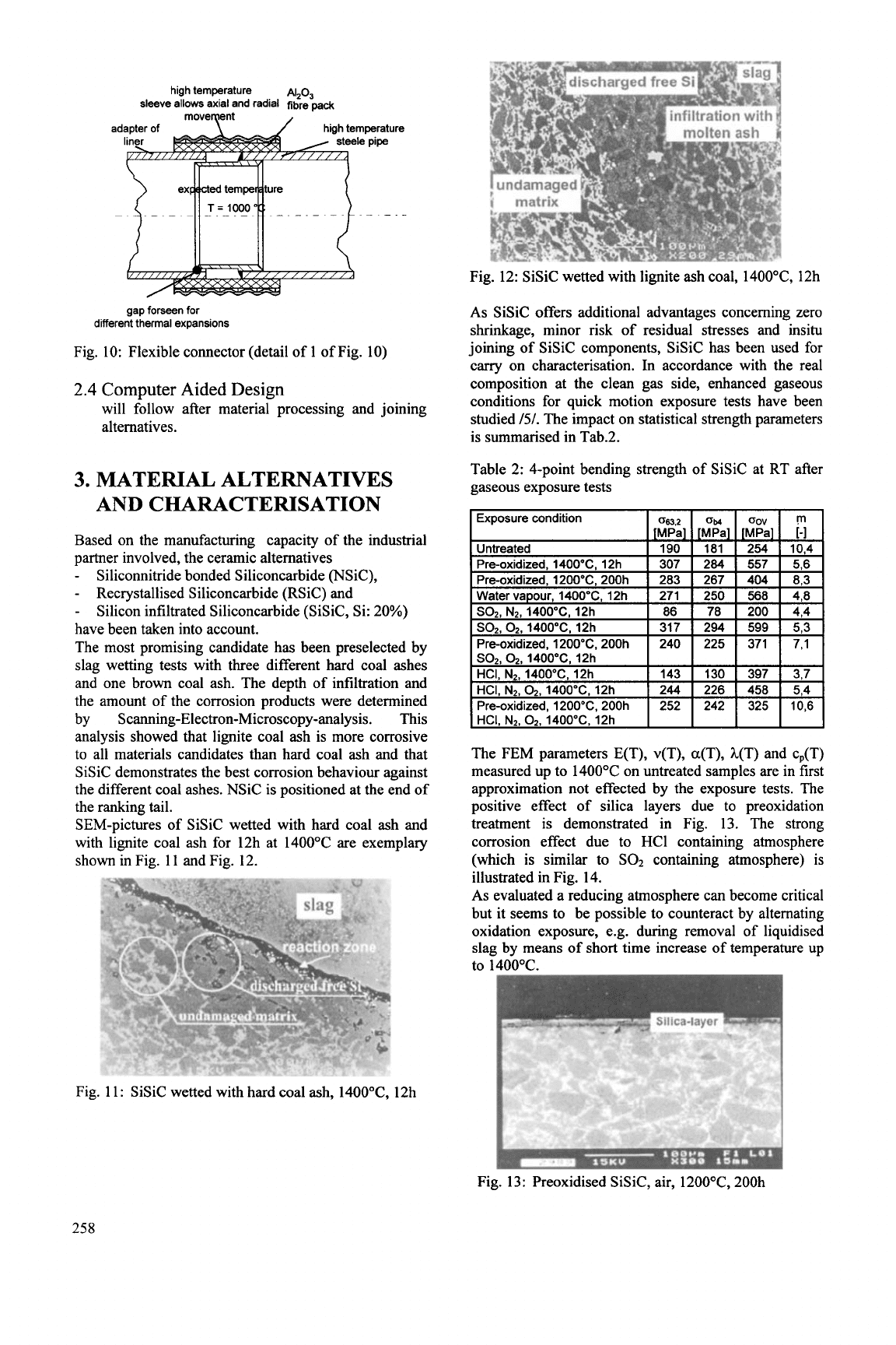
SEM-pictures of SiSiC wetted with hard coal ash and
with lignite coal ash for 12h at 1400°C are exemplary
shown in Fig. 11 and Fig. 12.
Fig. 12: SiSiC wetted with lignite ash coal, 1400"C, 12h
As
SiSiC offers additional advantages concerning zero
shrinkage, minor
risk
of residual stresses and insitu
joining of SiSiC components, SiSiC has been used for
carry on characterisation. In accordance with the real
composition at the clean gas side, enhanced gaseous
conditions for quick motion exposure tests have been
studied
/5/.
The impact on statistical strength parameters
is summarised in Tab.2.
Table 2: 4-point bending strength of SiSiC at RT after
gaseous exposure tests
I
Exposure condition
I
~enl,
I
OM
I
Gnv
I
rn
I
I
HCI.
N2,02,1400"C, 12h
I I
I
I
I
The FEM parameters E(T), v(T), a(T), h(T) and cp(T)
measured up to 1400°C on untreated samples are in first
approximation not effected by the exposure tests. The
positive effect of silica layers due to preoxidation
treatment is demonstrated in Fig. 13. The strong
corrosion effect due to HCl containing atmosphere
(which is similar to
SO2
containing atmosphere) is
illustrated in Fig. 14.
As evaluated a reducing atmosphere can become critical
but it seems to be possible to counteract by alternating
oxidation exposure, e.g. during removal of liquidised
slag
by
means of short time increase of temperature up
to 1400°C.
Fig. 11: SiSiC wetted with hard coal ash, 1400"C, 12h
Fig. 13: Preoxidised SiSiC, air, 12OO0C, 200h
258
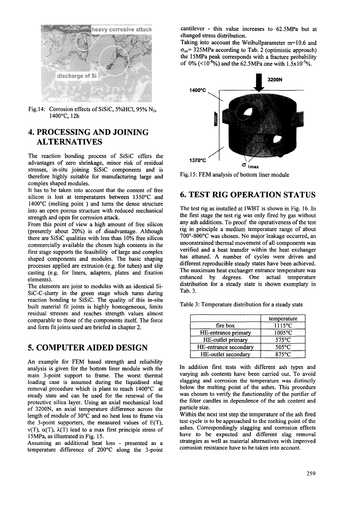
Fig.14: Corrosion effects of SiSiC, 5%HCI,
95%
NZ,
1400"C, 12h
4.
PROCESSING AND JOINING
ALTERNATIVES
The reaction bonding process of SiSiC offers the
advantages of zero shrinkage, minor risk of residual
stresses, in-situ joining SiSiC components and is
therefore highly suitable for manufacturing large and
complex shaped modules.
It has to be taken into account that the content of free
silicon is lost at temperatures between 135OOC and
1400°C (melting point
)
and
turns
the dense structure
into an open porous structure with reduced mechanical
strength and open for corrosion attack.
From this point of view a high amount
of
free silicon
(presently about 20%) is
of disadvantage. Although
there are SiSiC qualities with less than 10% free silicon
commercially available the chosen high contents in the
first stage supports the feasibility of large and complex
shaped components and modules. The basic shaping
processes applied are extrusion (e.g. for tubes) and slip
casting (e.g. for liners, adapters, plates and fixation
elements).
The elements are joint to modules with an identical Si-
Sic-c-sluny in the green stage which
turns during
reaction bonding to SiSiC. The quality of this in-situ
built material fit joints is highly homogeneous, limits
residual stresses and reaches strength values almost
comparable to those of the components itself. The force
and form fit joints used are briefed in chapter 2.
5.
COMPUTER AIDED DESIGN
An example for FEM based strength and reliability
analysis is given for the bottom liner module with the
main 3-point support to frame. The worst thermal
loading case is assumed during the liquidised slag
removal procedure which is plant to reach 140OOC at
steady state and can be used for the renewal of the
protective silica layer. Using an axial mechanical load
of
3200N, an axial temperature difference across the
length
of
module of 30°C and no heat
loss
to frame via
the 3-point supporters, the measured values of E(T),
v(T), a(T), h(T) lead to a max first principle stress of
1
SMPa,
as
illustrated in Fig.
15.
Assuming an additional heat
loss
-
presented as a
temperature difference of 200°C along the 3-point
cantilever
-
this value increases to 62.5MPa but at
changed stress distribution.
Taking into account the Weibullparameter m=lO.6 and
o,=
325MPa according to Tab. 2 (optimistic approach)
the 15MPa peak corresponds with a fracture probability
of
0%
(<lo-*%)
and the 62.5MPa one with 1.5~10'~%.
3200N
1
AOOOC
I
_-
1370'C
I
I/
lmax
Fig. 15: FEM analysis of bottom liner module
6.
TEST
RIG
OPERATION STATUS
The test rig
as
installed at IWBT is shown in Fig. 16. In
the first stage the test rig was only fired by gas without
any ash additions. To proof the operativeness of the test
rig in principle a medium temperature range of about
700"-800°C was chosen.
No
major leakage occurred, an
unconstrained thermal movement of all components was
verified and a heat transfer within the heat exchanger
has attuned. A number of cycles were driven and
different reproducible steady states have been achieved.
The maximum heat exchanger entrance temperature was
enhanced by degrees. One actual temperature
distribution for a steady state is shown exemplary in
Tab. 3.
Table 3: Temperature distribution for a steady state
575°C
HE-entrance secondary
I
505°C
HE-outlet secondary
I
875°C
I
In addition first tests with different ash types and
varying ash contents have been carried out. To avoid
slagging and corrosion the temperature was distinctly
below the melting point of the ashes. This procedure
was chosen to verify the fbnctionality of the purifier of
the filter candles in dependence of the ash content and
particle size.
Within the next test step the temperature
of the ash fired
test cycle
is
to be approached to the melting point of the
ashes. Correspondingly slagging and corrosion effects
have to be expected and different slag removal
strategies as well as material alternatives with improved
corrosion resistance have to be taken into account.
259
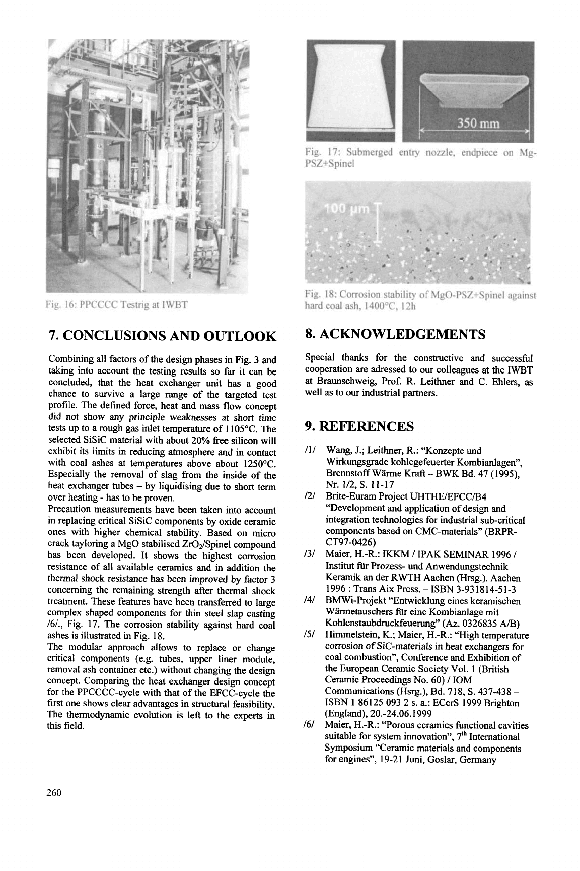
Fig. 16: PPCCCC Testrig at IWBT
7.
CONCLUSIONS AND OUTLOOK
Combining all factors of the design phases in Fig. 3 and
taking into account the testing results
so
far it can be
concluded, that the heat exchanger unit has a good
chance to survive a large range of the targeted test
profile. The defined force, heat and mass flow concept
did not show any principle weaknesses at short time
tests up to a rough gas inlet temperature of 1105°C. The
selected SiSiC material with about 20% free silicon will
exhibit its limits in reducing atmosphere and in contact
with coal ashes at temperatures above about 1250°C.
Especially the removal of slag from the inside of the
heat exchanger tubes
-
by liquidising due to short term
over heating
-
has to be proven.
Precaution measurements have been taken into account
in replacing critical SiSiC components by oxide ceramic
ones with higher chemical stability. Based on micro
crack tayloring a MgO stabilised ZQISpinel compound
has been developed. It shows the highest corrosion
resistance of all available ceramics and in addition the
thermal shock resistance has been improved by factor
3
concerning the remaining strength after thermal shock
treatment. These features have been transferred to large
complex shaped components for thin steel slap casting
161., Fig. 17. The corrosion stability against hard coal
ashes is illustrated in Fig. 18.
The modular approach allows to replace or change
critical components (e.g. tubes, upper liner module,
removal ash container etc.) without changing the design
concept. Comparing the heat exchanger design concept
for the PPCCCC-cycle with that of the EFCC-cycle the
first one shows clear advantages in structural feasibility.
The thermodynamic evolution is left to the experts
in
this field.
Fig. 17: Submerged entry nozzle, endpiece on Mg-
PSZ+Spinel
Fig. 18: Corrosion stability of MgO-PSZ+Spinel against
hard coal ash, 1400”C, 12h
8.
ACKNOWLEDGEMENTS
Special thanks for the constructive and successfbl
cooperation are adressed to our colleagues at the IWBT
at Braunschweig, Prof. R. Leithner and C. Ehlers,
as
well
as
to our industrial partners.
9.
REFERENCES
111
I21
131
I41
I51
I61
Wang, J.; Leithner, R.: “Konzepte und
Wirkungsgrade kohlegefeuerter Kombianlagen”,
Brennstoff Whne Kraft
-
BWK Bd. 47 (1 999,
Nr. 112,
S.
11-17
Brite-Euram Project UHTHE/EFCC/B4
“Development and application of design and
integration technologies for industrial sub-critical
components based on CMC-materials” (BRPR-
Maier, H.-R.:
IKKM
I
IPAK SEMINAR 1996
I
Institut
fiir
Prozess- und Anwendungstechnik
Keramik an der RWTH Aachen (Hrsg.). Aachen
1996
:
Trans Aix Press. -ISBN 3-931814-51-3
BMWi-Projekt “Entwicklung eines keramischen
Whnetauschers
fiir
eine Kombianlage mit
Kohlenstaubdruckfeuerung”
(Az. 0326835 A/B)
Himmelstein,
K.;
Maier, H.-R.: “High temperature
corrosion of SiC-materials in heat exchangers for
coal combustion”, Conference and Exhibition of
the European Ceramic Society Vol. 1 (British
Ceramic Proceedings
No.
60)
/
IOM
Communications (Hsrg.), Bd. 718,
S.
437-438
-
ISBN 1 86125 093 2
s.
a.: ECerS 1999 Brighton
(England), 20.-24.06. I999
Maier, H.-R.: “Porous ceramics functional cavities
suitable for system innovation”, 7” International
Symposium “Ceramic materials and components
for engines”, 19-2 1 Juni, Goslar, Germany
CT97-0426)
260
DESIGN AND TESTING
OF
CERAMIC COMPONENTS
FOR
INDUSTRIAL
GAS TURBINES
M. van Roode*, J.R. Price,
0.
Jimenez,
N.
Miriyala, and
S.
Gates,
Jr.
Solar Turbines Incorporated, San
Diego,
California,
USA
ABSTRACT
Solar Turbines Incorporated (Solar), under the
Ceramic Stationary Gas Turbine program sponsored by
the U.S. Department of Energy, has designed and
tested uncooled silicon nitride blades and nozzles and
continuous fiber-reinforced ceramic composite (CFCC)
combustor liners in the Solar Centaur-50s engine. The
paper will review the iterative component design and
testing
in
rigs and the engine.
INTRODUCTION
The Ceramic Stationary Gas Turbine (CSGT)
program was initiated by the United States Department
of Energy (DOE) Office of Industrial Technologies
(OIT) to develop ceramic technologies aimed at the
improvement of fuel efficiency and output power, and
reduction of
NOx
and CO emissions in stationary gas
turbines by replacement of cooled metal components
with uncooled ceramic parts. Solar is the prime
contractor on a team, which involves suppliers of
ceramic components, test laboratories, industrial end
users, and consultants. The three-phase program started
in
September 1992, and is scheduled to be completed at
the end of
2000.
Phase
I
focused on
concept/preliminary engine and component design,
ceramic materials selection, technical and economic
evaluation, and concept assessment. Phase
I1
which
began
in
April of 1993, addressed detailed engine and
component design, ceramic part procurement, long
term materials property testing, component rig testing,
engine testing, and destructive and nondestructive
component evaluation. Phase
Ill
which commenced
in
October of 1996, and which is still ongoing, involves
field tests at the cogeneration site of industrial end
users.
Solar selected the Centaur
50S,
a single shaft
engine for electrical generation and cogeneration
applications. The engine has a two-stage gas producer
turbine and single stage power turbine. The engine is
being retrofitted with uncooled first stage ceramic
blades, uncooled first stage ceramic nozzles, and
ceramic combustor liners. Figure
I
shows the Centaur
50s
engine layout with the components targeted for
ceramic insertion.
A
field test, an integral aspect of the
program, was originally envisioned to be for
4,000
hrs
at a design TRIT of
1
121OC. Because of the high risks
involved with the monolithic ceramic components, the
field test goals were subsequently relaxed to operation
at the baseline TRIT of 10IO°C of the Centaur 50s
engine. Short term in-house testing at the design target
TRIT is planned towards the end of
2000.
Summaries
of the CSGT program progress have been reported in
the literature [l-51.
Figure
I.
Solar Centaur
50s
Gas
Turbine with
Components Targeted for Ceramic Insertion
CSGT DESIGN-DEVELOPMENT STRATEGY
Based on the industrial gas turbine end user
expectations, i.e. a service life between overhauls of
30,000
hrs or more for continuous duty operation, risk
mitigation requirements were established which were
consistent with ceramic design practice. These
included limiting the number of ceramic components,
using well established and characterized materials as
well as promising new materials with potential cost-
effective scale-up to production applications, iterative
testing with stepwise increases in firing temperatures to
the final design TRIT, and minimizing steady state and
transient stresses in the ceramic components and
adjacent metal structures.
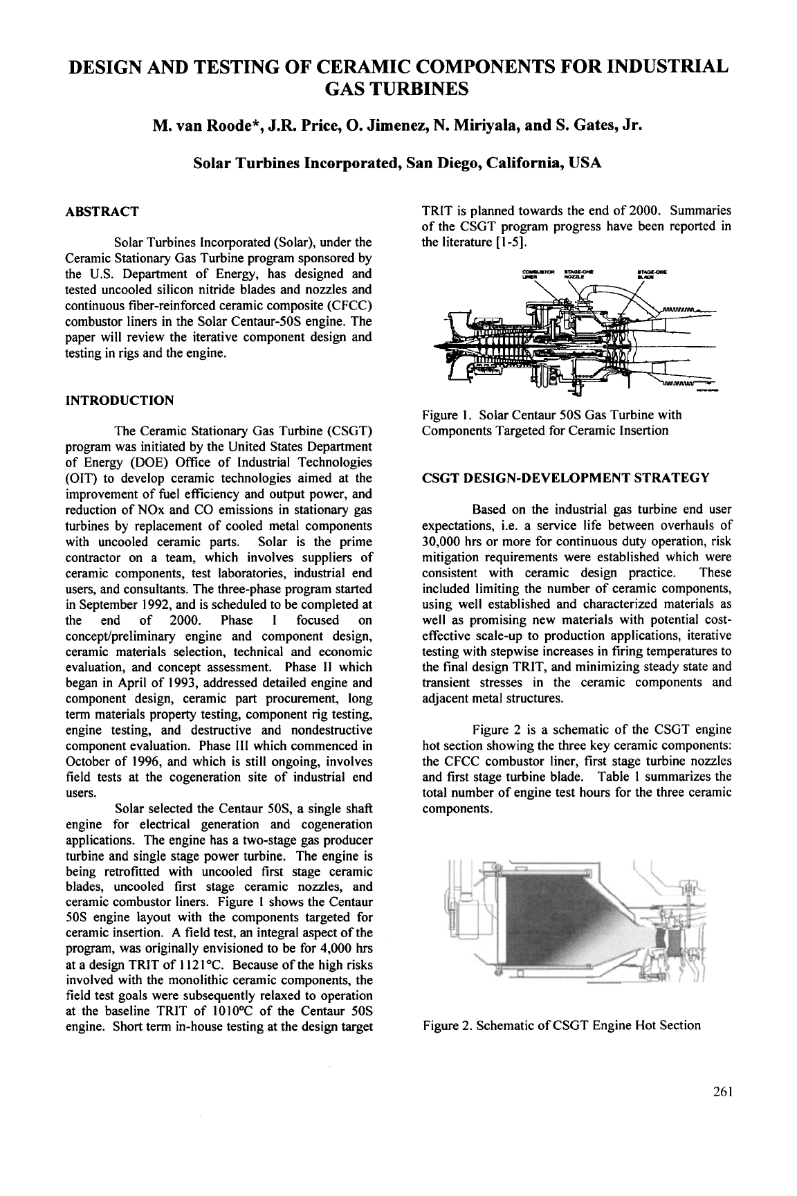
Figure
2
is a schematic of the CSGT engine
hot section showing the three key ceramic components:
the CFCC combustor liner, first stage turbine nozzles
and first stage turbine blade. Table
1
summarizes the
total number of engine test hours for the three ceramic
components.
Figure
2.
Schematic of CSGT Engine Hot Section
26
1