Heard D.E. (editor) Analytical Techniques for Atmospheric Measurement
Подождите немного. Документ загружается.

318 Analytical Techniques for Atmospheric Measurement
The Brewer-Mast cell (Brewer & Milford, 1960) consists of a single electrochemical cell
with a silver anode and a platinum cathode. A polarizing voltage of 0.42 V is applied.
The free iodine generated in the reaction is converted back to iodide ions at the cathode:
I
2
+2e
−
→ 2I
−
At the anode two electrons are released to the circuit via ionization of two silver atoms:
2Ag → 2Ag
+
+2e
−
In this manner each O
3
molecule bubbled through the solution gives rise to the flow
of two electrons in the circuit. From knowledge of the pump-driven flow (220 cc/min)
through the bubbler, the concentration of O
3
in air is derived.
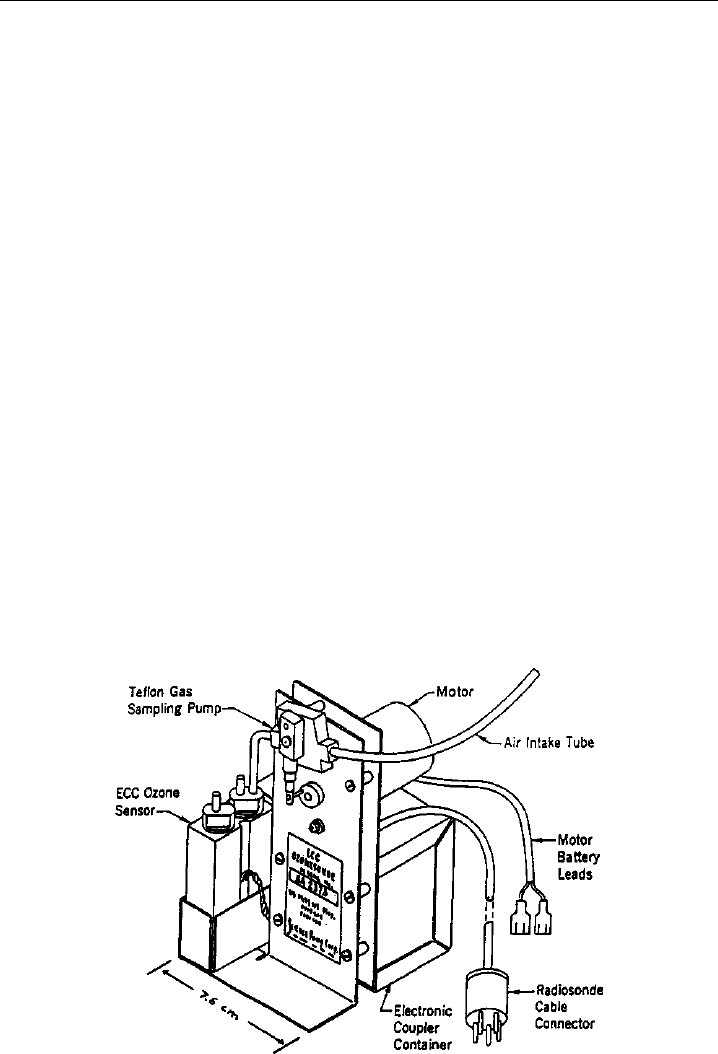
The electrochemical concentration cell (ECC) consists of two chambers, an anode
chamber and a cathode chamber of differing KI concentrations, connected by an ion
bridge, which provides an ion pathway for the current and prevents mixing of the two
solutions. A schematic diagram appears in Figure 7.3 (Komhyr et al., 1995). As for the
Brewer-Mast cell, a current is measured which is proportional to the ozone concentration.
As part of the data reduction procedures, a correction factor for loss of pumping
volume at reduced pressure is applied, a zero-ozone background current is subtracted,
and the profile is scaled to match a measurement of the total ozone column, making
an allowance for ozone above the maximum height of the sounding (WMO, 1998).
Comparison studies have shown that between the tropopause and ∼28 km, different
sondes show consistent results. Precisions are less than 3% and systematic biases are
Figure 7.3 A schematic diagram of an electrochemical concentration cell (ECC) used for the routine
measurement of O
3
profiles by ozonesondes. (Figure 1 of Komhyr et al., 1995, printed with permission
from American Geophysical Union.)

Chemical Methods 319
smaller than 5%. For the troposphere, with its small ozone amounts, errors are larger,
with systematic differences of 10–15%, with the Brewer-Mast sonde being less precise
than ECC sondes. The ECC sonde has a precision better than 5–10% and a positive bias of
3%. However, the differences are not simply due to the sonde type, but different stations
using the same type of sonde can show systematic differences due to different preparation
and correction procedures. The network would benefit from greater standardization.
The extensive data sets generated from the sounding stations have enabled analyses
of trends and distributions of O
3
in the troposphere, which is not well sampled by
satellite instruments. Logan (1999) determined, for example, that the broad summertime
maximum in O
3
at northern middle and high latitudes extends all the way up to the
tropopause, with median concentrations at their peak of 125–200 ppbv in June–July,
while being a factor of 2 smaller in the winter. Also, the effects of biomass burning can
be observed in the secondary O
3
peak in the South Atlantic in December–January due to
the transport of O
3
and its precursors from the Northern Hemisphere. A similar biomass
burning feature is observed at Samoa in the middle and upper troposphere in October.
7.4 Nitrogen compounds NO NO
2
NO
y
via
chemiluminescence with O
3
7.4.1 The NO + O
3
reaction
Reactive nitrogen is generally introduced into the atmosphere as NO, which readily (few
minutes) establishes a steady state with NO
2
during the daytime. Further oxidation gives
rise to other members of the reactive nitrogen family NO
y
. Active nitrogen NO
x
=NO+
NO
2
is important for its role in tropospheric O
3
formation and its role in catalytic O
3
destruction in the stratosphere. Fundamental to the principle of measurement of reactive
nitrogen compounds is the chemiluminescent reaction of NO and O
3
, and contrary to the
case of the reactions used in the measurement of O
3
by heterogeneous chemiluminescence,
the mechanism of this gas-phase reaction has been thoroughly studied. Clyne et al. (1964)
determined its mechanism to involve the production of excited NO
2
in some fraction of
the reactions (7.1), followed by fluorescence (7.3) of those excited NO
2
molecules that
are not collisionally quenched (7.4):
NO +O
3
→ NO
2
∗
+O
2
(7.1)
NO +O
3
→ NO
2
+O
2
(7.2)
NO
2
∗
→ NO
2
+h (7.3)
NO
2
∗
+M →NO
2
+M (7.4)
Also, the spectrum of the radiation was found to be electronic in origin, with a short
wavelength limit of 590 nm and extending to at least 1100 nm. The temperature depen-
dence of the chemiluminescence is almost entirely due to the temperature dependence of
the NO
2
∗
production reaction, and it is favored by an increase in temperature. Clough
and Thrush (1967) extended this work by measuring the intensity distribution of the

320 Analytical Techniques for Atmospheric Measurement
chemiluminescence over the range 600–2600 nm, mapping out the peak near 1200 nm, as
well as the rate constants for the two branches (7.1) and (7.2). They also determined the
temperature dependence of the quantum yield for the chemiluminescent branch (7.1),
and while there is some discrepancy about the magnitude of this quantum yield, this
yield increases with increasing temperature. Clough and Thrush (1967) found a yield
of 7% at 300 K, while Schurath et al. (1991) found 20%; both found an increase with
temperature. Following this initial work, some half dozen determinations of the rate of the
overall reaction have been made and form the basis of the currently recommended values
(A = 3 ×10
−12
cm
3
molecule
−1
s
−1
E/R = 1500 K, Sander et al., 2000). This detailed
knowledge of the fundamental properties of the chemiluminescent reaction of NO and
O
3
is an aid in the design of instruments for the measurement of reactive nitrogen and
O
3
, as illustrated in the next section.
7.4.2 The measurement of nitric oxide (NO)
Fontijn et al. (1970), Stuhl and Niki (1970), and Stedman et al. (1972) recognized that
the chemiluminescent reaction of NO and O
3
could be used to measure either NO or O
3
in ambient air. Fontijn et al. (1970) demonstrated the feasibility of the method for NO
measurements in polluted air by finding a linear response over the range of 4 ppbv to
100 ppmv with no interferences from NO
2
,CO
2
, CO, C
2
H
4
,NH
3
,SO
2
, and H
2
O. Stuhl
and Niki (1970) and Stedman et al. (1972) built a prototype instrument that was used
for measurements in a polluted urban environment. It had a detection limit of 1.5 ppbv
S/N = 3. They found modest interferences from metal carbonyls and C
2
H
4
, but these
are greatly diminished by the use of a filter to cut off light with <648 nm, where
the chemiluminescence due to these species primarily occurs, and which is below the
wavelength range of the bulk of the NO
2
emission. Red filters are common features of
later designs as well, so that other potential interferences are also minimized.
Ridley and Howlett (1974) built an automated instrument for deployment in the
stratosphere, motivated by the need to assess the potential impact of supersonic aircraft
on stratospheric ozone. A cylindrical reaction vessel was built and viewed axially by a
PMT. Provided that there is an adequate flow of reagent O
3
to maintain a high enough
concentration for near-complete conversion of NO to NO
2
(dependent on mass flow and
pressure of the reaction vessel), and provided that collisional quenching (7.4) dominates
chemiluminescence (7.1), they derived that the chemiluminescence intensity is given by
I =
k
1
k
3
k
1
+k
2
i
k
4i
M
i
F
NO
where k
1
k
2
k
3
, and k
4
are the rate constants for the above reactions, F is the volume flow
rate into the reaction vessel, and [NO] is the concentration of NO to be measured (Ridley
et al., 1972; Ridley & Howlett, 1974). This can be further simplified to demonstrate the
fundamental dependence of instrumental sensitivity S on flow and pressure:
S =
CF
0
P

Chemical Methods 321
where F
0
is the mass flow rate of sample air, P is the reaction vessel pressure, is
the NO mixing ratio, and C is a proportionality factor (see also Ridley, 1978). This
shows that sensitivity is enhanced by increasing the sample flow, within the constraints
of practicality imposed by the need to deploy the instrument on an aircraft or balloon,
and also by minimizing the pressure so that quenching is minimized and the excited
NO
2
molecules are allowed to fluoresce. Based on these design principles, Ridley &
Howlett (1974) were able to achieve a sensitivity improvement to 30 pptv for a 1 s
detection limit. Chemiluminescence instruments generally operate in a regime where the
O
3
concentration is high enough that virtually all of the NO reacts with O
3
within view
of the PMT. Of those that react, the fraction that become excited NO
2
∗
is in the range
5–20% (depending on temperature and laboratory results adopted; see above), and of
these about one in a thousand (at most) radiate prior to collisional quenching. Thus the
signal is proportional to total flow and inversely proportional to the pressure due to the
dominance of the quenching process over fluorescence.
Optimization of a chemiluminescence instrument is also improved by modest elevation
of the reaction vessel temperature (to 30–40
C) to increase the rate of overall reaction
((7.1) and (7.2)) and also to favor the chemiluminescence branch (7.1). However, there
is no point in increasing the temperature too far as it results in too much heat transfer
to the red-sensitive PMT, which must be kept cool (e.g. using dry ice) to minimize
background dark counts within the PMT itself. Moreover background counts from the
reaction vessel also increase at elevated temperatures. Temperature- and pressure-control
of the reaction vessel, when possible, can also contribute to the stability of instrument
sensitivity. Another critical factor is the reflective property of the reaction vessel, and
gold-plating is often employed.
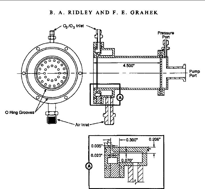
Ridley and Grahek (1990) describe a widely-used reaction vessel design (Figure 7.4). It
is machined from stainless steel and then highly polished and gold plated to maximize
the reflectivity and the number of photons collected from the chemiluminescent reaction.
It has a volume of 230 cm
3
L = 45
D =2
and is designed for operation with a sample
flow of 1000 sccm at a pressure of 5–10 torr. The reagent flow is 100–200 sccm of 3–4%
O
3
in O
2
, which is produced by flowing high-purity O
2
through a silent discharge. The
sample and reagent gases are each distributed in an annular ring at the photomultiplier
end of the reaction vessel, and they are mixed in an annular fashion as they enter the
vessel just in front of the PMT, in order to maximize the amount of light collected. With
its modest flow requirements and its small size, it is suitable for deployment on aircraft
where space savings are critical. Yet the instrument sensitivity (7 counts per second per
pptv) and detection limit (1–2 pptv at 10 s) are still quite good for most purposes.
Chemiluminescence instruments are zeroed by switching the ozone flow to a volume
just upstream of the reaction vessel to allow the NO+O
3
reaction and attendant chemi-
luminescence to occur upstream of the reaction vessel and out of view of the PMT. This
allows measurement of the background signal due to the PMT dark current plus a signal
due to presence of O
3
in the reaction vessel, likely due to wall luminescence (Ridley &
Howlett, 1974; Kley & McFarland, 1980). This background signal is subtracted from the
measure mode signal to give the signal proportional to ambient NO. A measurement
artifact is commonly observed when sampling synthetic air with no NO, a gas for which
there should be no difference between the zero and measure mode signals. However,
there generally is a small difference, and its origin is not well understood, but since it
322 Analytical Techniques for Atmospheric Measurement
Figure 7.4 Mechanical design of an NO reaction vessel used in many research-grade chemilumi-
nescence instruments. (Figure 1 of Ridley & Grahek, 1990, printed with permission from American
Meteorological Society.)
is related to cleanliness of the reaction vessel, it may be related to wall luminescence
(Kley & McFarland, 1980). At any rate, this artifact is routinely measured and applied
as a correction to the measure-minus-zero signal. Since this artifact signal may be of
the order of 10 pptv or less, it is not significant in polluted environments, but in clean,
remote regions the magnitude and uncertainty of the artifact signal may be a limiting
factor. As NO is stable at ppmv levels in a mixture with N
2
in compressed gas cylinders,
calibration is generally achieved by the periodic addition of a known mixing ratio to the
sample inlet.
A complicating issue is the variation of quenching efficiency with the identity of the
third body in reaction (7.4). Matthews et al. (1977) drew attention to this for studies
of combustion systems where a large variety and quantity of combustion products were
present. As a practical matter for most atmospheric measurements, it is water, and its
variability, that is most critical, as it is abundant in the atmosphere and a much better
quencher than dry air. As Matthews et al. (1977) demonstrate, the quenching efficiency,
and therefore the instrument sensitivity, can vary with the concentration of water and

Chemical Methods 323
other species in the reaction vessel. Hence calibrations should be performed via NO
addition on top of ambient air, rather than synthetic air. Also, for measurements in
humid air, it points to the need for a correction to the instrument sensitivity based on
simultaneous measurements of H
2
O vapor. Interestingly, Carroll et al. (1985) found it
beneficial to add a constant flow of water, at 2–3% of the total flow, directly to the
reaction vessel. Even though the increased quenching due to H
2
O decreases instrument
sensitivity by about 15%, overall performance is improved because the background signal
is also reduced and stabilized, the artifact is reduced, and the start-up settling time is
shortened. Ridley et al. (1994) describe the proper way to correct for sensitivity to ambient
H
2
O vapor. It essentially requires adjusting real-time sensitivity calibrations back to zero
ambient H
2
O, employing ambient H
2
O vapor measurements combined with a relative
quenching coefficient for H
2
O, while taking into account the dilution of the sample flow
by the ozonizer flow and the added H
2
O flow into the reaction vessel. The sensitivity at
the time of measurement can then be similarly determined using the ambient H
2
O vapor
measurements.
Chemiluminescence instruments for nitrogen species are widely used for atmospheric
measurements. They have been deployed for research studies on aircraft of many types,
as well as balloons and rockets, covering remote regions of the globe and also extending
through most of the stratosphere. In addition, they are used for routine monitoring of
pollution at ground sites, generally using commercially available instruments. An exciting
early result from these instruments was the observation of extremely low mixing ratios,
only a few pptv, in the boundary layer of the remote Pacific (McFarland et al., 1979). While
initially difficult to reconcile with models, these low values were later confirmed by aircraft
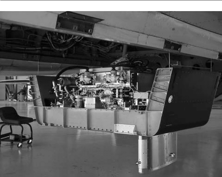
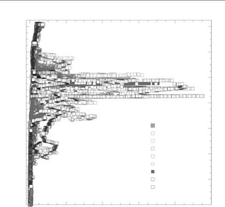
measurements (e.g. Ridley et al., 1987). As an example of more recent research, Figure 7.5
illustrates the installation of an automated NO-NO
y
instrument in the lower fuselage of a
high-altitude aircraft (NASA WB-57), and Figure 7.6 shows NO measurements from this
deployment which demonstrate that Florida thunderstorms inject prodigious amounts of
lightning-produced NO into the upper troposphere, where lightning can be a dominant
source of NO
x
which can affect O
3
levels in the upper troposphere well downstream of
thunderstorm regions (Ridley et al., 2004).
7.4.3 The measurement of nitrogen dioxide NO
2
The ready detection of NO via chemiluminescence in turn enables the detection of other
reactive nitrogen species which can, with specificity, be converted to NO, and while a
number of instruments have been built and a number of papers have been written, it
is the aspect of specificity which has generated the most concern. It appears that Sigsby
et al. (1973) were the first to describe such an instrument in the literature. It employed
a 6-ft length of 1/8-inch stainless steel tubing heated to 750–900
CasanNO
2
-to-NO
converter, and by switching the converter in and out of the sample flow path, signals
for (a) NO plus NO
2
and (b) just NO could alternately be obtained. The difference
would be the signal for NO
2
but for the fact that NH
3
was also converted to NO by
this system. By the addition of a scrubber for NH
3
, Sigsby et al. (1973) were able to
correct for this, but compounding the number of differences required of signals which
were not actually simultaneous added uncertainty to the measurement. Also, it was not
324 Analytical Techniques for Atmospheric Measurement
Figure 7.5 Photograph of an automated NO-NO
y
instrument mounted in a lower-fuselage pallet (1 of 4)
on the NASA WB-57F. The instrument is hoisted into position so that the pallet forms the lower fuselage
skin. The heated sample inlet extends below the pallet. (Photo courtesy of David J. Knapp.)
clear to what extent other potential interferents were specifically tested. On the other
hand, Winer et al. (1974) did a systematic study of several potential interferents to the
determination of NO
2
using molybdenum and carbon converters, namely PAN, ethyl
nitrate, ethyl nitrite, nitroethane, and HNO
3
. They found that PAN was converted just
as efficiently as NO
2
, as were ethyl nitrate and ethyl nitrite. HNO
3
was converted less
efficiently but to a significant extent. Thus the measurements from such a converter are
difficult to interpret, but they concluded that they more nearly yield a measure of total
oxides of nitrogen NO
y
, rather than NO plus NO
2
, but of course if HNO
3
were the
dominant oxide of nitrogen, it would not be an adequate measurement since it is not
converted with unit efficiency. Matthews et al. (1977) performed a similar study for a
stainless steel converter and with similar results, including significant conversion of HCN
and incomplete conversion of NH
3
.
A far more specific technique, a photolytic one rather than a surface catalytic one, was
proposed by Kley and coworkers (Kley & McFarland, 1980; Kley et al., 1981), who shone
a xenon arc lamp on a Pyrex photolysis cell in which sampled air had a residence time of
the order of 2–3 s. There was enough UV power and residence time to achieve conversion
of 60% of the NO
2
to NO. Via calibration with a known flow of NO
2
, this conversion
efficiency can be determined, and this, combined with a measurement of NO, allows
NO
2
to be determined. The NO signal is subtracted from the signal via the illuminated
Chemical Methods 325
NO (pptv)
CRYSTAL-FACE: WB-57F (2002)
18
16
14
12
10
8
6
4
0 2000 4000 6000 8000 10000
GPS Altitude (km)
0711
0716
0719
0721
0723
0726 ascent
0731 ascent
0728
0729
Figure 7.6 Chemiluminescence measurements of NO, largely produced by lightning, at near-tropical
latitudes over and near southern Florida, illustrating thunderstorm outflow up to the local tropopause,
but with peaks values a couple of km below. NO mixing ratios are 10–50 times background amounts,
showing that lightning can be major source of O
3
-producing NO
x
to this region. (Figure 12c of Ridley
et al., 2004, printed with permission from American Geophysical Union.)
photolysis cell, and the difference is divided by the conversion efficiency to yield NO
2
.
The known flow of NO
2
is generated either from an NO
2
permeation device or using a
known flow of NO converted to NO
2
via near-complete reaction with O
3
.
The photolytic technique has potential for much greater specificity than does a
technique using a hot catalytic surface. Many of the potential interferents for an NO
2
measurement, such as HO
2
NO
2
,N
2
O
5
, ClONO
2
, and PAN, are thermally unstable and
prone to convert to NO
2
when exposed to heat. On the other hand, the absorption
spectra of these species as well as other interferents (e.g. HONO and NO
3
) show much
weaker absorption in the 300–400 nm range compared with NO
2
(Figure 7.7). Specificity
is further enhanced by the use of a 320 nm cutoff filter (Kley & McFarland, 1980), because
of the spectral differences evident in Figure 7.7.
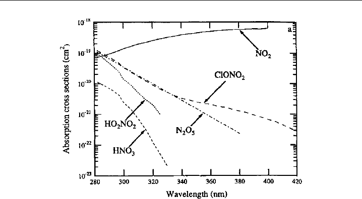
326 Analytical Techniques for Atmospheric Measurement
Figure 7.7 UV absorption spectra of NO
2
and several potential interferent compounds, illustrating the
discrimination that can be obtained via photolytic conversion at wavelengths in the 350–400 nm range.
(Figure 1 of Gao et al., 1994, printed with permission from American Geophysical Union.)
A complication with the technique is an artifact signal that occurs, even when no NO
2
is present in the sample flow. In such a case, the signal should be the same whether
the light is shining on the photolysis cell or not. However, Kley and McFarland (1980)
found such a signal to be present and that its intensity was related to the cleanliness
of the cell, suggesting that this artifact is caused by wall contaminants such as HNO
3
adsorbed from the gas phase or as nitrate in aerosol form. As with the artifact in the NO
measurement, this NO
2
artifact may routinely be determined using synthetic air, and a
correction applied. If it is too large, then the cell requires cleaning.
Bollinger et al. (1984) used the photolytic technique to obtain measurements of NO
2
with a detection limit of 10 pptv for a 1 s integration time. Combined with NO measure-
ments with a detection limit of 2 pptv at 1 s, very low mixing ratios of below 20 pptv
were measured at a surface site in the Colorado mountains. The high sensitivity of these
instruments allowed the determination of what at the time seemed to be exceptionally
low mixing ratios of NO
x
for a continental surface site, but it was possible to explain the
low values in terms of the synoptic meteorology which brought air to the high-altitude
site unperturbed by ground-level sources.
In view of the number of NO
2
conversion techniques that have been used for field
measurements, it has been necessary to conduct side-by-side comparisons of instru-
ments to insure identical conditions. In a ground-based study, Fehsenfeld et al. (1987)
compared the photolytic technique to catalytic conversion on a solid ferrous sulfate
surface (Dickerson et al., 1984) and found the catalytic technique to be subject to signif-
icant interferences from n-propyl nitrate (NPN) and PAN based on tests with known
amounts of those species. Ridley et al. (1988a) made a comparison of the same two
techniques but aboard a NASA Convair 990 aircraft and with a similar conclusion. Since
the airborne ferrous sulfate converter gave rise to levels about three times higher than the
photolytic converter, it was concluded that the ferrous sulfate converter was likely subject
Chemical Methods 327
to an interferent, possibly PAN. In a companion paper, Ridley et al. (1988b) presented a
modified version of photolysis/chemiluminescence instrument. A 45
ultraviolet mirror
was used to reflect only the useful radiation from the arc lamp into the photolysis cell,
preventing the unwanted visible and infrared light from illuminating the cell. The use
of the ultraviolet mirror combined with a lens to keep most of the light from shining
on the cell walls reduced the NO
2
artifact signal described above. In addition, the mass
flow rate through the cell and its pressure were held constant, giving rise to a constant
conversion efficiency and a stable calibration. The paper also describes a sampling issue
that can lead to erroneous NO
2
values if not properly calibrated and corrected for, and
that is due to the conversion of NO to NO
2
by reaction with O
3
, both homogeneous
and heterogeneous, in the sampling line and photolysis cell. The apparent sensitivity will
vary with ambient O
3
, but factors are derived to correct for this (Ridley et al., 1988b).
The 1-min detection limit at 0–2 km (5–7 km) was 7 pptv (15 pptv) for a 1 min average.
This allowed the airborne measurement of NO
x
in regions of a tropopause fold and
demonstrated that stratospheric NO
x
could be introduced over a wide vertical range in
the troposphere and not just at the tropopause, as assumed in many models at the time.
Given the proven benefits of using photolytic converters rather than heated catalysts,
further developments in photolysis/chemiluminescence measurements of NO
2
have come
from improved light sources. Gao et al. (1994) used a metal halogen lamp in a photolytic
converter deployed on the NASA ER-2. This lamp is much more efficient in generating
useful UV light than the xenon arc lamp, while the heat load is still significant but
manageable on the high-flying ER-2, where there is a ready supply of cold air. The initial
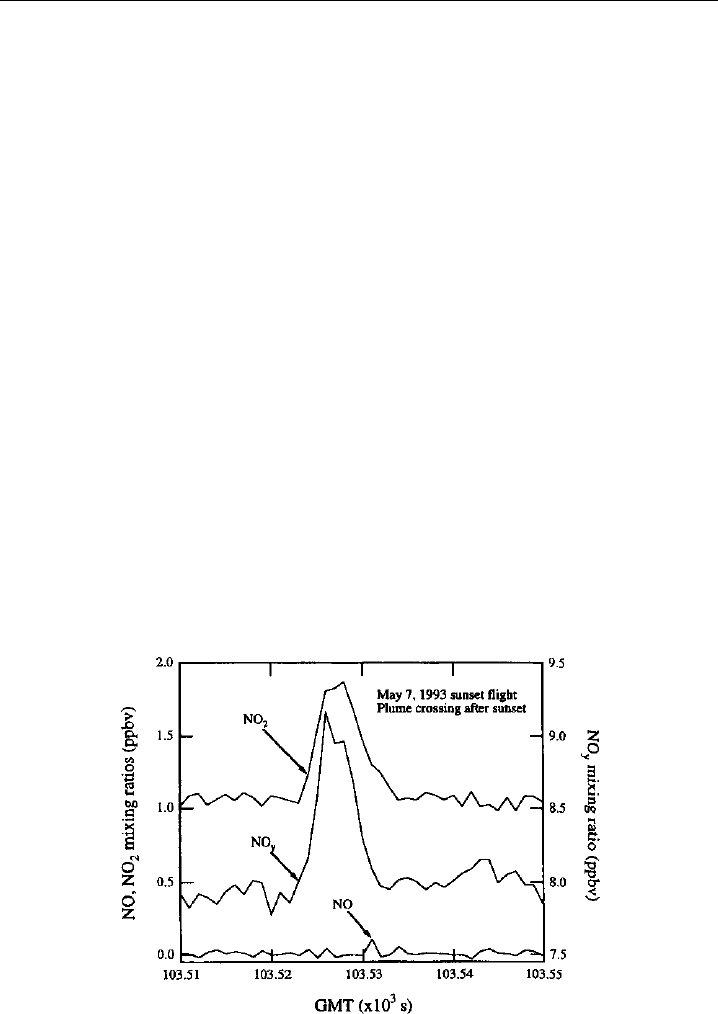
instrument had a conversion efficiency of only about 0.37, and it was adequate to resolve
the NO
2
in the exhaust plume of the ER-2 (Figure 7.8). Eventual improvements in the
instrument centered on a change in the combination of filters used (del Negro, 1999)
Figure 7.8 Measurements obtained with NO, NO
2
, and NO
y
chemiluminescence instruments aboard
the NASA ER-2 as it samples its own exhaust. The good time response (1-sec points are plotted) of both
the chemiluminescent detector itself and the photolytic converter enable good resolution of the plume.
The sampling occurred after local sunset so that all of the NO has been converted to NO
2
. (Figure 14 of
Gao et al., 1994, printed with permission from American Geophysical Union.)
