Hawkes P.W., Spence J.C.H. (Eds.) Science of Microscopy. V.1 and 2
Подождите немного. Документ загружается.


Chapter 9 Photoemission Electron Microscopy (PEEM) 665
transmission. A multipole stigmator–defl ector is located close to the
back focal plane of the objective lens to compensate astigmatism and
alignment errors. The intermediate lens and projective lens transfer
and magnify the image onto a microchannel plate or a phosphor
screen. This phosphor transforms the electron into a visible image,
which is captured by a CCD camera.
3.1 The Objective Lens
The objective lens is the most important component of the electron
optical system. Triode and tetrode cathode lenses have been used.
Chmelik et al. compared several types of cathode lenses (Chmelik et
al., 1989). Rempfer et al. analyzed different objective lens types based
on extensive electron optical bench measurements (Rempfer et al., 1999;
Rempfer and Griffi th, 1989).
The lens evaluation occurs in four steps: (1) calculation of the fi eld
distribution of the lens, (2) calculation of the electron trajectories and
the electron optical properties, (3) evaluation of the interaction of the
lens with other parts of the electron optics, and (4) tolerance analysis
in regard to mechanical errors. Often an analytical treatment is not
possible and numerical methods must be used, which benefi t from the
rapid progress in computer technology. A charged particle optics
(CPO) program was developed by Read for solving charged particle
optics problems using the surface charge method (Harting and Read,
1976).* Munro has developed a series of electron optics programs using
the fi nite element method (Hawkes, 1973; Orloff, 1997). Perhaps the
most popular program used in electron optics is SIMION 3D (http://
www.simion.com) which was developed by Dahl (Dahl, 2000). SIMION
is an electrostatic and magnetic fi eld modeling program that solves the
fi eld using a fi nite element method and traces the motion of electrons
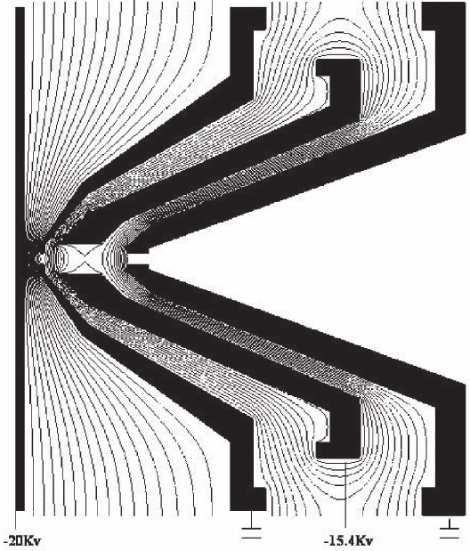
using a fourth-order Range-Kutta integrator. Figure 9–7 shows the
equipotential contours of a tetrode objective lens, calculated using
SIMION. The acceleration fi eld is approximately uniform in the vicin-
ity of the optical axis except close to the anode aperture. The aperture
acts as a thin diverging lens (Rempfer and Griffi th, 1989; Davisson and
Calbrick, 1932).
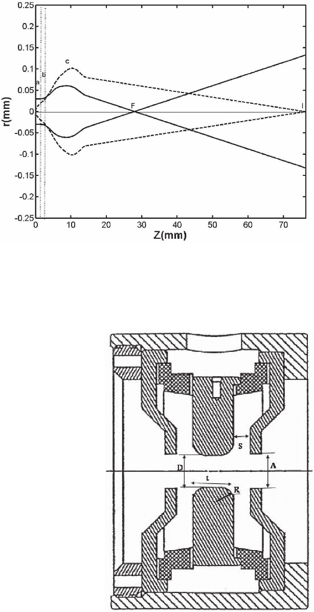
The objective lens can be characterized by the trajectory of the prin-
cipal rays, the fi eld ray and the axial ray (Figure 9–8). The calculation
treats the electrodes as a single lens because the fi elds overlap, but it is
instructive to describe the objective lens optics as being composed of
(1) the accelerating fi eld, (2) a weak diverging lens, and (3) a unipoten-
tial lens. The acceleration fi eld forms a virtual image at unit magnifi ca-
tion at twice the sample distance l. The weak diverging lens created by
the aperture of the fi rst electrode forms another virtual image at dis-
tance 3/l behind the sample. It is demagnifi ed by M = 2/3. Finally, the
unipotential lens forms a real image with a typical magnifi cation of
M = 10–40 (Anders et al., 1999; Schneider and Schöhense, 2002; Watts
et al., 1997).
* Student versions of the program are available at no coot from http://www.
electronoptics.com/.
666 J. Feng and A. Scholl
3.2 The Intermediate and Projective Lens
The intermediate and projective lenses magnify the image of the objec-
tive lens without distortion to reach a fi nal magnifi cation typically
between 30 and 4000. The angle and energy-dependent aberrations of
the intermediate and projective lenses are negligible because the energy
and angular spread of the electron beam are small here. However, the
distortion aberrations need to be minimal because the object size after
magnifi cation by the objective lens is signifi cant, fractions of a milli-
meter or more. Therefore, the intermediate and projective lenses are
designed to work at minimum focal length. As the excitation of the
electrostatic lens is increased, its focal length decreases and the object
side focal point enters the lens fi eld. The distortion coeffi cient can reach
zero at minimum focal length. This type of lens has been examined in
detail by Rempfer et al. (1991) who studied rotationally symmetric,
three electrode, unipotential lenses (Figure 9–9). The term unipotential
means that the image and object side electrodes are on the same poten-
tial. Important lens parameters are the thickness of the center electrode
t, the interelectrode spacing S, the diameter of the center electrode D,
the diameter of the end electrode aperture A, and the radius of the
center electrode R. Starting with parameters chosen from diagrams
Figure 9–7. Equipotential contours of the electric fi eld of an electrostatic
PEEM objective lens at 20 kV sample voltage.
Chapter 9 Photoemission Electron Microscopy (PEEM) 667
Figure 9–8. Principal electron rays in an objective lens: dashed line, axial ray;
solid line, fi eld ray; F, back focal plane; I, image plane.
Figure 9–9. Electrode
geometry of a symmet-
ric unipotential lens.

668 J. Feng and A. Scholl
published by Rempfer (1985), the lens properties can be optimized for
a particular application using numerical methods.
3.3 Transmission and Spatial Resolution of PEEM
The microscope transmission and spatial resolution determine the
quality of a PEEM. Bauer (1991) has used these two quantities to defi ne
a quality factor. The spatial resolution determines how well spatial
details are preserved, and the transmission determines the noise level
in an image and the acquisition speed (Jacobsen et al., 1992; Schneider,
1998). The sample is an integral part of PEEM optics, and the optimum
resolution can be achieved only on ideally fl at surfaces. The effects of
roughness and sample tilt have been previously discussed (Marcus,
2001; Nepijko et al., 2000).
3.3.1 Transmission
The microscope transmission is defi ned as the fraction of emitted elec-
trons that reaches the detector. To reduce aberrations most microscopes
contain several apertures of different size that can be moved into the
electron beam. Thus transmission can be traded for resolution. The
aperture confi nes the electron beam to the paraxial region and can also
limit the energy acceptance of the microscope. Using E/(E + w
f
)
4
for
the electron energy distribution for a work function w
f
and using
Lambert’s law for the electron angular distribution, the transmission
of PEEM can be evaluated in a simple closed form
T
if
=−
+
1
1
1
22
[( )( )]af U/W/
*
(1)
Here, a is the aperture radius, U is the sample potential, and f
i
* is the
image side focal length of the objective lens. A high sample potential
and a large aperture improve transmission, whereas a long focal length
and large work function reduce transmission (Feng et al., 2002).
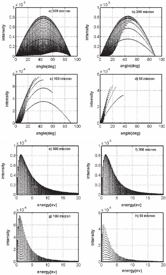
Figure 9–10 shows SIMION simulations of the angle and energy
distribution of the electrons transmitted through apertures of different
size. Every point represents one electron. Both the energy spread and
the transmission decrease with decreasing aperture size. Note that
high-energy, paraxial electrons still pass through the aperture. The
resolution is dominated by electron diffraction when the aperture size
is lowered beyond a certain minimum value. Therefore, apertures with
a diameter larger than 10 µm are usually used.
3.3.2 Spatial Resolution
The spatial resolution of microscopes is characterized by a spread func-
tion. The spread function describes the microscope image of a chro-
matic point source and a diverging electron beam. Diffraction, spherical,
and chromatic aberrations are regarded as independent contributions
and are added quadratically. The total resolution is given by
r rrr
tot s
2
c
2
d
2
=++
(2)
where the third-order spherical aberration is defi ned as
r
s
= C
s
α
3
(3)
Chapter 9 Photoemission Electron Microscopy (PEEM) 669
Figure 9–10. SIMION simulations of the angle and energy distribution of the
emitted electrons that are accepted by X-PEEM when apertures of different size
are used. (a–d) The angle; (e–h) the energy distribution.
the fi rst-order chromatic aberration is defi ned as
r
c
= C
c
αδE/(E) (4)
and the diffraction disk is defi ned as
r
d
= 0.61λ/α (5)
670 J. Feng and A. Scholl
Here, C
s
and C
c
are the spherical and chromatic aberration coeffi cients,
λ and E are the electron wavelength and the electron energy, δE is the
electron energy spread, and α is the half angle of the pencil beam
passing the back focal plane aperture. Though Eqs. (2)–(5) can be easily
solved, the results are often misleading because the contributions of
aberrations and diffraction are not Gaussian and therefore the equations
give only a rough estimate of the microscope resolution.
An alternate way of characterizing the spatial resolution is by deter-
mining the spatial frequency transfer of the microscope. The intensity
distribution of an image produced by a point object under incoherent
illumination is called the impulse response function h(x, y). The object
intensity distribution f(x, y) and the image intensity distribution g(x, y)
are related by the convolution equation
gxy f x y hx xyydxdy() (,)( , ), =−−
∫∫
11 1 1 11
(6)
After a Fourier transformation one obtains
G( f
x
, f
y
) = F( f
x
, f
y
) ⋅ H( f
x
, f
y
) (7)
G, F, and H are Fourier transforms of g(x, y), f(x, y), and h(x, y). The
function H( fx, fy) is the complex optical transfer function (OTF), with
real and imaginary parts
OTF( f ) = |H( fx, fy)|e
iφ( f )
(8)
The real part |H( fx, fy)| is called the modulation transfer function
or MTF, and the function φ( f ) is called the phase transfer function.
Figure 9–11. Measured (black dots) and calculated (solid line) modulation
transfer function (MTF) of PEEM-2 at the Advanced Light Source.
Chapter 9 Photoemission Electron Microscopy (PEEM) 671
Experimentally, the MTF is measured as the contrast with which spatial
frequencies of an object are transferred to an image. Higher frequencies
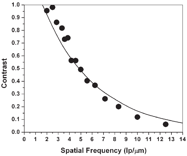
correspond to smaller object features. Figure 9–11 shows the measured
and calculated MTF of PEEM-2 at the Advanced Light Source using an
extraction fi eld of 20 kV and a 12-µm aperture (Doran et al., in prepara-
tion). It starts with unity modulation transfer at low frequencies and
gradually drops at higher spatial frequencies. A transfer of 1 indicates
that the spatial detail of an object at that frequency is perfectly trans-
ferred, while zero transfer indicates a complete loss of information.
Values between 0 and 1 indicate partial transfer of spatial frequencies
and a reduced contrast. The Rayleigh criterion for spatial resolution is
equivalent to a 9% contrast transfer, which is reached for a frequency
corresponding to a feature size of 35 nm. Often a higher contrast is
required in experiments. At about 80 nm PEEM-2 reaches 40% contrast
transfer. The agreement between experiment and simulation over a
wide spatial frequency range confi rms the accuracy of the simulation.
4 Aberration-Corrected PEEM Microscopes
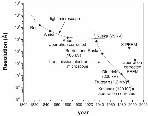
The improvements in resolution of light and electron microscopes over
the past two centuries are compared in Figure 9–12 (Rose, 1994). At the
beginning of the twentieth century the light microscope had reached
its best resolution after the invention of aberration correction by Abbe,
using a combination of a concave and a convex lens, called an achromat
lens. The electron microscope soon surpassed the resolution of optical
microscopes because of the much smaller wavelength of kilovolt elec-
Figure 9–12. History of microscopy techniques and evolution of spatial reso-
lution. Shown are signifi cant steps in the development of optical microscopy,
electron microscopy, and X-PEEM. (From Rose, 1994).

672 J. Feng and A. Scholl
trons, effectively removing the effect of diffraction, if electrons of suf-
fi ciently high energy are used. Today, the electron microscope has not
reached the diffraction limit and lens aberrations still dominate. Among
these aberrations, astigmatism, coma, and fi eld distortions can either
be easily corrected or they are small close to the optical axis of the
microscope*. Early in the development of electron optics theory, Scher-
zer showed that simple electron lenses always suffer from two other
important aberrations: chromatic and spherical aberrations (Scherzer,
1936). The electron-optical analogue to a light-optical achromat does
not exist. Different approaches have been tried to remove these aber-
rations by relinquishing one of the conditions of Scherzer’s theorem,
which applies only to simple lenses (Hawkes et al., 1996). Multipole
aberration correctors, which use a nonrotationally symmetric fi eld,
have been successfully used in a low-voltage scanning electron micro-
scope (SEM) (Zach and Haider, 1998), in transmission electron micro-
scopes (TEMs) (Haider et al., 1995, 1998), and in scanning transmission
electron microscopes (STEMs) (Dellby et al., 2001; Batson et al., 2002).
X-PEEM has much larger aberration coeffi cients than SEM or TEM,
because of the large energy width of the secondary electron distribu-
tion, the low initial electron energy, and the large fi eld of view. There-
fore, the aberrations of X-PEEM are corrected using an electron mirror,
which has approximately opposite chromatic and spherical aberrations
of the objective lens.
4.1 Aberrations of an Electron Lens
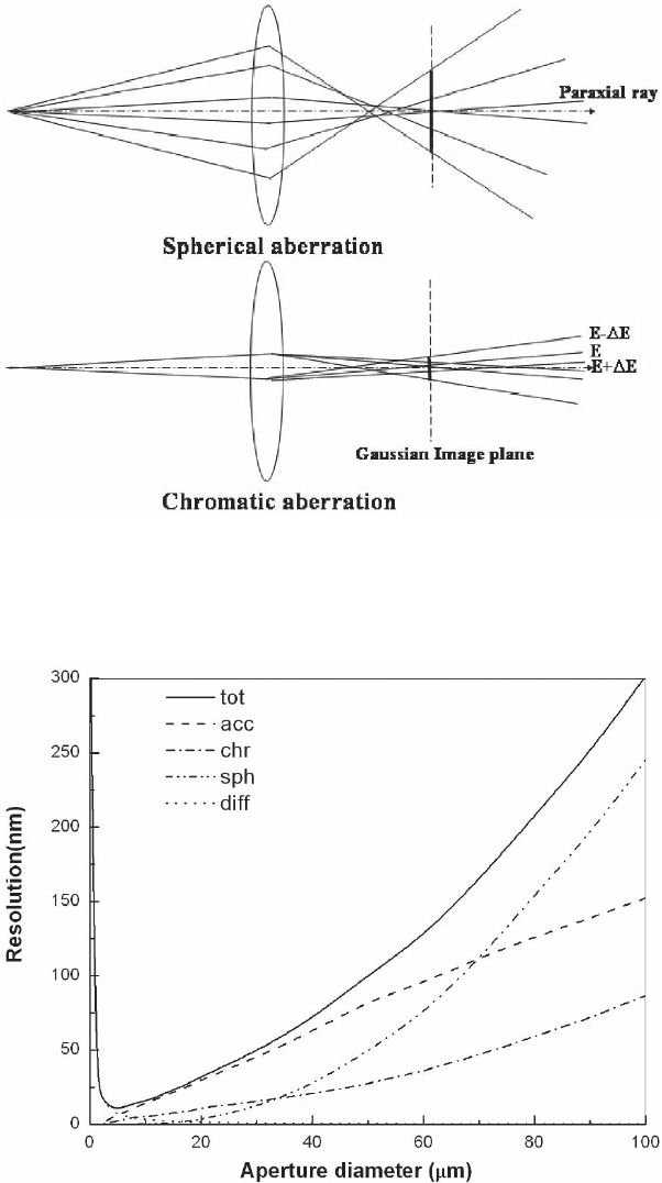
The electron trajectories in an electron lens are affected by spherical
and chromatic aberrations (Figure 9–13). The Gaussian image plan is
defi ned as the intersection of the paraxial ray with the optic axis. The
spherical aberration refers to the variation of the focal distance with
the angle of a ray from the paraxial ray. An electron passing the lens
far from its center experiences a higher fi eld and is focused more
strongly. The focus lies before the image plane. The chromatic aberra-
tion refers to the variation of the focal distance with the electron energy.
Slower electrons experience the fi eld for a longer time and are focused
more strongly. The focus lies before (slow electrons) or behind (fast
electrons) the image plane.
Figure 9–14 shows the resolution of a typical X-PEEM with a 2-mm
acceleration gap and 20-kV acceleration fi eld for a 4-eV work function,
broken down according to the source of the aberration. Dominant are
the aberration caused by the accelerating fi eld and the chromatic aber-
ration of the lens. Although the resolution can be improved by using
a very small aperture, the usefulness of this approach is limited because
of the severe reduction in microscope transmission and the onset of
diffraction at very small aperture sizes. An ultimate resolution of close
to 20 nm has been achieved in several instruments (Anders et al., 1999;
De Stassio et al., 1999; Bauer, 1997; Schönhense and Spiecker, 2002).
* A simple electrostatic lens is rotational symmetric, uses static fi elds, is space
charge free, and the electronic lenses does not reverse its direction.
Chapter 9 Photoemission Electron Microscopy (PEEM) 673
Figure 9–13. Illustration of spherical (top) and chromatic (bottom) aberrations
of an electron lens.
Figure 9–14. Contributions of various aberrations to the total resolution limit
on uncorrected PEEM. Sample voltage 20 kV, gap = 2 mm, work function w
f
=
4 eV. tot, total aberration; acc, aberration of accelerating fi eld; chr, chromatic
aberration of objective lens; sph, spherical aberration of objective lens; diff,
contribution of diffraction.
674 J. Feng and A. Scholl
Aberration correction promises to signifi cantly improve the ultimate
resolution beyond this limit and also to increase the transmission of
X-PEEM at moderate resolution by a factor of 100 (Bauer, 2001).
4.2 An Aberration-Corrected Microscope Using an Electron Mirror
The idea of using an electron mirror to correct the chromatic and spheri-
cal aberration of a round lens dates back more than half a century
(Zworykin and Kosma, 1945; Ramberg, 1949). Extensive studies of elec-
tron mirrors have been performed by Kel’man (1973, 1974), Dodin (1981),
Rempfer (1990, 1992, 1997), Shao (1990a, 1990b), and Rose (1995, 1997),
and co-workers. An electron mirror uses a refl ecting electrode with a
suffi ciently high negative potential to reverse the propagation direction
of the electron beam. In 1990, Shao and Wu proposed using an electron
mirror with more than two electrodes to be able to freely adjust the
aberration coeffi cients.
73
Through numerical analysis of a four-
electrode electric mirror, they showed that spherical and chromatic
aberrations can be adjusted electrically without changing the image
distance of the mirror. Later, a more sophisticated theoretical model
using a time-dependent perturbation method was developed by Rose
and Preikszas (1995) to fully understand the mirror system. Integral
expressions for the aberration coeffi cients of an electron mirror were
derived and higher order aberrations were studied. Currently, two
aberration-corrected PEEM microscopes using electron mirrors are
being built. The fi rst is called SMART (SpectroMicroscope for All
Relevant Techniques) in Germany and has been designed as an ultra-
high-resolution spectromicroscope for BESSY II, Germany (Fink et al.,
2003). The second is called PEEM-3 at the Advanced Light Source, USA,
and has been designed for the study of magnetic materials and poly-
mers. Both microscopes rely on the correction of chromatic and spheri-
cal aberrations using a hyperbolic electron mirror, which was pioneered
by Rempfer and co-workers (1997). Here, we will focus on the electron
optical system of the aberration-corrected PEEM-3 experiment, although
many aspects of the two aberration-corrected microscopes are similar
and are based on the Rose design.
Figure 9–15 shows a schematic overview of the electron optics of
PEEM-3. The electrons travel through the microscope along the dashed
lines. The objective lens, together with the fi eld lens, forms a telescopic
round lens system. This allows the mirror to run in the so-called sym-
metric mode in which fi rst-order chromatic distortion and third-order
coma vanish and curvature of fi eld effect is reduced (Rose and
Preikszas, 1992). A set of two electric dodecapoles steers the beam into
the magnetic separator and corrects astigmatism. For a single defl ection
of 90°, the beam separator images its entrance plane 1 : 1 onto its exit
plane, without introducing aberrations of second order or dispersion of
the fi rst or second degree. The electron mirror images the mirror-side
exit plane of the beam separator back onto itself. To cancel coma gener-
ated by the mirror, the magnifi cation of the mirror is chosen to be −1
(Wan et al., 2004). The separator then transfers the aberration-corrected
image to the projector optics, which magnify the image. A pair of elec-
tromagnetic dodecapoles in the mirror arm steers the beam into the
mirror and back into the separator. A CCD camera behind the mirror is
