Hawkes P.W., Spence J.C.H. (Eds.) Science of Microscopy. V.1 and 2
Подождите немного. Документ загружается.


Chapter 4 Analytical Electron Microscopy 285
The emission current density J for thermal sources is related to the
material and the operation temperature T and follows the Richardson’s
law
J = AT
2
exp(−φ/KT) (2)
where A is a constant of the material (the Richardson constant given
in units of A/cm
2
K
2
), and φ is the workfunction. The fi eld emission
current is related to the tunneling process and thus to the electric fi eld
at the tip. For Schottky emission, the workfunction is effectively reduced
by a factor ∆φ due to the strong electric fi eld applied to the tip and
becomes
φφφφ πε
eff
=− =−∆ eeE4
0
where E is the electric fi eld (in
the order of 10
8
V/m) , ε
0
is the vacuum permittivity, and e is the electron
charge. This reduction of the workfunction arises from the well-
established Schottky effect (e.g., Solymar and Walsh, 2004) that effec-
tively increases the emission current by a factor exp(∆φ/kT) (Egerton,
2005) due to the negative term in the exponential factor in Richardson’s
law [Eq. (2)]. The temperature of the source will affect the temporal
coherence of the source and the energy spread of the electrons due to
thermal energy. The source size and the angular spread α will affect
the spatial coherence. Considering the source size, the temperature of
the source, the vacuum requirements, and the brightness, the sources
can be compared (Table 4–3).
It is possible to comment on the merits of the various electron sources
for AEM. The high brightness of the cold FEG makes it the ideal tool
for analytical work requiring a small probe. Minimal source demagni-
fi cation is required as the source size is in the order of 10 nm although
the ultimate probe size and shape will depend on electron optical
considerations related to aberration of the probe forming optics (see
below). An additional advantage of the cold FEG is the low energy
Table 4 –3. Comparison of sources.
Schottky
emission Thermal FEG Cold FEG
Thermionic Thermionic FEG (ZrO on W (100) (W single
Characteristic W hairpin LaB
6
W crystal) orientation crystal)
f (eV) 4.5 2.7 2.8 4.5 4.5
J
c
(A/m
2
) ª10
4
ª10
6
ª10
7
ª10
7
–10
8
ª10
9
a (rad) ª10
-2
ª10
-2
ª10
-3
ª10
-3
–10
-4
ª10
-4
d (mm)
a
ª50 ª10 ª0.02–0.03 ª0.01–0.1 ª0.01
Brightness [A/(m
2
sr)]
b
ª10
9
ª10
10
ª10
11
–10
12
ª10
12
ª10
12
–10
13
Temperatu re (K) 2700 1800 1800 1600 300
Energy spread (eV) 1–3
c
0.6–2
c
0.6–1.5
c
0.6–0.8 0.3
Vacuum (Pa) 10
-2
10
-4
10
-7
10
-7
10
-8
a
Specifi c values depend on the exact tip confi guration.
b
The brightness values are given for 100-keV electrons and scale linearly with accelerating voltage. The reduced
brightness is given by B/V (where V is the accelerating voltage in volts).
c
The energy spread is dependent on the operation condition of the gun (the bias of the Wehnelt, fi lament heating
current, or the extraction voltage of the Schottky FEG).
286 G. Botton
spread of the electron source allowing, in principle, detailed analysis
of the energy loss near-edge structures in EELS spectra. Although the
ultimate brightness of the Schottky sources is lower by about one order
of magnitude, the practicalities of the less stringent vacuum and demon-
strated reliability have made the Schottky guns very common within
the AEM fi eld. Worth mentioning is the fact that the total current might
be a more important parameter for some AEM analysis techniques
such as energy-fi ltered imaging when a large fi eld of view needs to be
illuminated (with enough current per individual pixel in a map). In
that case, the thermionic emission sources (LaB
6
in particular) provide
very large total currents. New research is in progress to develop alter-
nate even brighter sources by exploiting low workfunction materials,
carbon nanotube electronic properties (Fransen et al., 2005), and semi-
conductor p–n junctions.
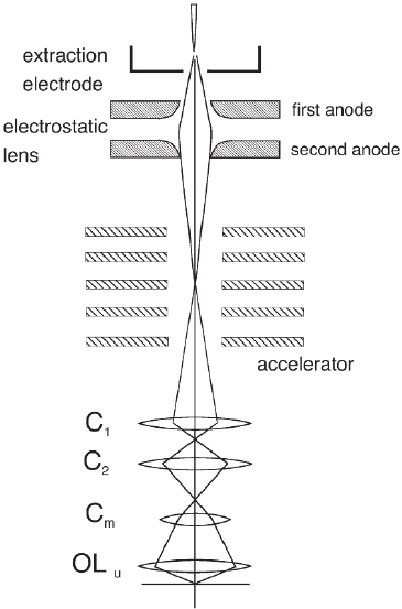
Once the electrons are accelerated by the anode stack to the high-
voltage potential of the TEM, the condensing optics demagnifi es (Figure
4–12) the source image in the plane of the sample. In this chapter we
will not describe the various aberrations and defects of lenses but refer
the reader to other chapters in this book. We remi nd the reader, however,
that all round electromagnetic lenses have positive spherical aberration
coeffi cients C
s
(in the order of C
s
= 0.5–1.0 mm for high-resolution micro-
scopes offering limited sample tilt and a small polepiece gap and
around C
s
= 1.5–3 mm for large tilt and large polepiece gaps). Electro-
magnetic lenses also suffer from chromatic aberrations C
c
in the order
of C
c
= 1–2 mm and that, just as in light optics, the wave nature of elec-
Figure 4–12. Schematic
diagram of a fi eld emission
electron gun with gun anodes
(also called gun lens) and the
accelerating anodes (acceler-
ating the electrons up to
the accelerating voltage of
the TEM). The illumination
system consists of condenser
lenses (C
1
, C
2
, C
m
) and the
objective lens (OL). See the
text for function details.

Chapter 4 Analytical Electron Microscopy 287
trons imposes a diffraction limit to the resolution as imposed by the
Rayleigh criterion. Given these imperfections of the lenses and wave
nature of electrons, the probe size at the specimen level d
0
is limited not
only by the demagnifi ed image source size d
s
but also by a combination
of the aberration of the illumination system (spherical and chromatic)
and the diffraction limit of the probe-forming aperture all added in
quadrature (Spence and Zuo, 1992; Reimer, 1984)
d
2
0
= d
2
s
+ d
2
d
+ d
2
sa
+ d
2
c
+ d
2
f
(3)
where d
s
is the demagnifi ed source image, d
d
= 0.6λ/α is the diffraction
limit broadening, d
sa
= 0.5 C
s
α
3
is the spherical aberration broadening,
d
C
= (∆E/E
0
)C
C
α is the chromatic aberration contribution of the probe
forming lens, d
f
= 2α∆f is the defocus contribution to a small defocus
error where α is the convergence half-angle at the specimen determined
by the condenser C
2
aperture limiting the probe and ∆f is the defocus
of the probe forming lens. The size of the unaberrated probe source
image d
s
is related to the defi nition of brightness that, as mentioned
above, is constant through the illumination system (from the gun to the
sample) and is determined as
dIB
sb
=
(
)
2 πα
where I
b
is the beam
current. Calculations of the unaberrated source size therefore assume
that the current at the sample is known (or can be measured).
Equation (3) assumes incoherent illumination, i.e., all electrons at the
aperture are not in phase and every point within the aperture can be
considered as an independent source. Strictly speaking, this assump-
tion is not valid for high brightness fi eld emission sources (and for
particular operating conditions of thermionic electron sources) and it
is necessary to defi ne the conditions where incoherence in illumination
applies to determine the conditions of validity of Eq. (3) for the calcula-
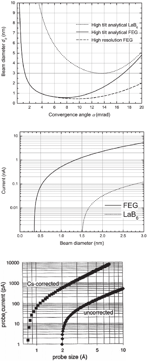
tion of the probe size. Due to the various aberration terms in Eq. (3)
there is an optimum probe size as a function of the illuminating angle.
Plots for two microscope confi gurations and sources are shown in
Figure 4–13 for a high-resolution microscope confi guration—not dedi-
cated to analytical work but for designed optimum imaging resolution
(low tilt angle in the specimen area: ±20–24°)—and for a high-tilt ana-
lytical confi guration (±35–40°). It is clear that the use of FEG allows
smaller probes. Based on the equations above and typical gun bright-
nesses for Schottky guns, it is possible to calculate the probe current
dependence with probe size, calculated based on the incoherent illu-
mination condition, for an FEG and an LaB
6
source (Figure 4–14). We
also demonstrate the effect of reducing the spherical aberrations in the
probe-forming lens using the recently developed correctors in a cold
FEG-scanning transmission electron microscope (STEM) operating at
100 kV based on the data reported in the literature (Dellby et al., 2001)
(Figure 4–15). For the latter case, Eq. (3) needs to be modifi ed to account
for the limited residual aberrations (see Chapter 2, this volume; Dellby
et al., 2001).
As discussed above, the coherence of the source is a key concept that
needs to be considered for high-brightness fi eld emission sources and
analytical microscopy. In conditions of coherent illumination all elec-
trons can be considered to be emitted by a single point source and all
288 G. Botton
Figure 4–13. Variation of the electron
probe size for analytical TEM work as a
function of the illumination aperture
convergence for instruments equipped
with different electron sources and
lenses.
Figure 4–14. Variation of the electron
beam current with electron probe size
for two instruments equipped with a
thermionic source and Schottky FEG.
Figure 4–15. Variation of the probe current as
a function of probe size for a conventional cold
fi eld emission source dedicated scanning trans-
mission electron microscope and an aberration
corrected cold-FEG microscope. (From Dellby
et al., © 2001. Reprinted with permission from
the Japanese Microscopy Society.)
Chapter 4 Analytical Electron Microscopy 289
are in phase in the illuminating aperture and on the electron wavefront
at the sample. This condition implies that interference effects between
electrons can occur. A detailed discussion on coherence and sources
can be found in Spence and Zuo (1992) and we summarize the key
elements of coherence relevant to the discussion on the probe size for
the purpose of discussing the ultimate limits of the instrumentation.
Following the concepts developed in classical optics, it is necessary to
consider the transverse coherence width X
a
concept related to the width
of the electron beam in the plane of the condensor aperture X
a
=
λ/(2πθ
s
) = f
C
2
λ/(πd
s
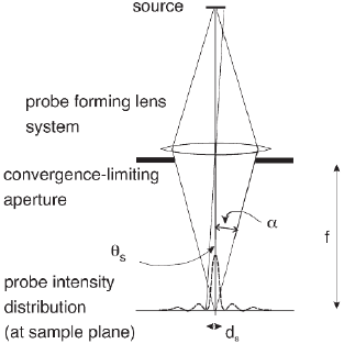
) where θ
s
is the angular width of the probe of size
d
s
(i.e., not the convergence angle) as subtended at the condensor aper-
ture (Figure 4–16). This angle can be determined geometrically given
a probe size d
s
and focal length f
C
2
of the probe-forming lens. Source
points in the aperture plane closer than X
a
can interfere as in a slit
experiment with coherent light. This transverse coherence term must
be compared with the diameter of the probe-forming aperture D
C
2
to
determine if the illumination is coherent or not. If X
a
<< D
C
2
, the aper-
ture is incoherently illuminated and all points in the illumination
aperture can be considered as emitting independently. Still, for a given
aperture of convergence angle α incoherently fi lled, the coherence
width will be X
s
= λ/(2πα). Object points at the sample separated by a
distance smaller that X
s
will be illuminated coherently and will give
rise to interference effects.
In the other extreme, if X
a
> D
C
2
, the aperture is coherently fi lled and
the electron wavefront illuminating the sample will be in phase. For
example, for the smallest probe in an FEG (say 0.2 nm), a C
2
aperture
of 5 µm would be coherently fi lled. At 200 keV, for a LaB
6
emitter and
a probe size of about 3 nm, one would need an aperture of 0.5 µm for
the coherence criterion to be fulfi lled. By changing the illumination
conditions (demagnifi cation of the source and reducing the accelerat-
ing voltage) and the condenser aperture, the coherence illumination
condition could be achieved even for thermionic sources as demon-
strated by Dowell and Goodman (1973).
In coherent illumination conditions, the terms contributing to the
determination of the probe size cannot be added incoherently as inde-
Figure 4–16. Factors entering
the description of the source
coherence for illumination of
samples. (Adapted from Spence and
Zuo, 1992.)
290 G. Botton
pendent contributions [as done in Eq. (3)] and detailed calculations
based on the incident electron wavefunction and the transfer function
of the objective lens must be carried out. It has been demonstrated that
with the judicious choice of defocus of the probe forming lens, sub-
Ångstrom electron probes can be obtained even without aberration
correctors (Nellist and Pennycook, 1998) to improve imaging resolution
albeit with very small currents and tails to the intensity distribution
containing up to 50% of the beam current. Such beams, although rele-
vant for optimal imaging resolution, are therefore not suitable for ana-
lytical work. Optimum probe sizes (Mory et al., 1987) for analytical work
are achieved with convergence α
C
and defocus ∆f conditions deter-
mined by α
C
= 1.27 C
s
−1/4
λ
1/4
and ∆f = −0.75 C
s
1/2
λ
1/2
. In these optimal
conditions, the probe size containing 80% of the intensity is d
(80%)
=
0.4 C
s
1/4
λ
3/4
. For aberration corrected instruments these terms need to be
revised to correctly treat the contributions of the residual aberrations
as discussed in Dellby et al. (2001) and in Chapter 2 (this volume).
2.2 Electron Optic Confi guration
In the discussion so far we have made abstraction of the technical
aspects necessary to achieve the demagnifi cation of the source required
for small probe analysis and the need to provide, with the same system,
illumination at the sample for conventional imaging and energy-
fi ltered microscopy. Modern instruments capable of conventional TEM
and STEM are based on the double condensing optic system (C
1
+ C
2
)
with the addition of a supplementary weaker condenser lens C
m
(called
“condenser minilens” or “minicondenser”) and a strong magnetic fi eld
before the sample (i.e., a prefi eld) generated by an objective lens (OL)
composed of two parts: an upper lens and a lower lens surrounding
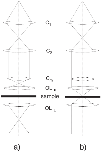
the sample (Figure 4–17). “Parallel” illumination at the sample plane
is achieved by a combination of C
2
and C
m
yielding, at the focal point
of the objective lens, a convergent beam that is then made parallel by
the strong upper objective lens fi eld (Figure 4–17a). A small probe
required for analytical work or for STEM imaging and analysis in
STEM mode is obtained by effectively optically switching the C
m
off
(using various schemes depending of the exact location of the C
m
lens)
and by making use of the strong OL prefi eld (of the upper objective
lens) to achieve large convergence angles and large source demagnifi -
cation (Figure 4–17b). Practically speaking, this mode of operation is
called the nanoprobe or energy-dispersive spectrometry (EDS) mode.
STEM operation for these microscopes is achieved in exactly the same
electron-optical confi guration. FEGs (cold and Schottky) have an addi-
tional electrostatic gun lens (Figure 4–12) leading to additional demag-
nifi cation of the source and more fl exibility in the gun operation. The
strength of the C
1
lens determines the fraction of electrons (hence the
current) that will enter the C
2
aperture and the demagnifi cation of
the source. A strongly excited C
1
lens will give rise to larger demagni-
fi cation and, conversely, a weakly excited C
1
lens will result in a smaller
demagnifi cation and more current entering the C
2
aperture. In this
fi xed operation mode, changes in the convergence angle are achieved
Chapter 4 Analytical Electron Microscopy 291
by changing the physical aperture size (using a strip aperture contain-
ing four to eight apertures, including a top hat Pt aperture for analyti-
cal work—see Sections 2.3.6 and 7.2 on instrumental contributions in
EDXS analysis). Continuous change in convergence is achieved by
controlling the strength of the C
m
lens and OL prefi eld or/and addition
of a third condenser lens.
The electron optical confi guration required for STEM imaging and
analysis is achieved, in a TEM-STEM instrument capable of both opera-
tion modes and, as discussed above, with the combination of the C
m
lens optically switched off and the subsequent focus of the nearly par-
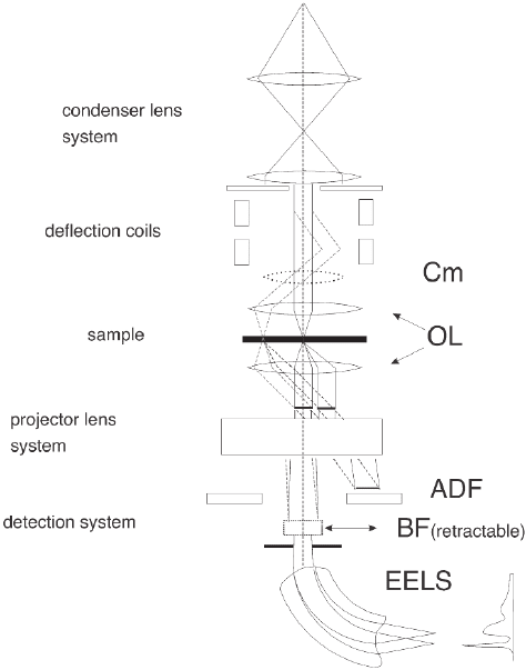
allel beam into a small source image by the upper OL fi eld. The scan-
ning operation of the beam over the sample is carried out by defl ection
coils located before the specimen (optically before the upper objective
lens) so that the beam is shifted (but not tilted) on the specimen plane
(Figure 4–18). As the beam is rastered pixel by pixel over the area of
sample of interest, various signals (including analytical information)
can be recorded sequentially at each position to form images and ele-
mental maps based on analog or digital signals recorded synchro-
nously (e.g., bright-fi eld, secondary electrons, backscattered electrons,
annular dark-fi eld electrons, and EELS, EDXS, etc). Dedicated com-
mercial STEM instruments (offering no TEM operation mode) built by
the company Vacuum Generator in the 1980s and 1990s have tradition-
ally been equipped with cold FEG and, in the later models, operate
with a gun lens, two condenser lenses, and an asymmetric objective
lens (no imaging lenses are necessary). Their design is based on the
gun located at the “bottom” of the microscope column for stability
reasons with the detectors at the “top.” New commercial instruments
Figure 4–17. Electron optical
confi guration of the illumina-
tion system of a double-objective
lens system. Confi guration (a)
describes the formation of paral-
lel illumination while confi gura-
tion (b) describes the conditions
needed to achieve a highly
convergent and small focused
electron beam.
292 G. Botton
developed based on the same approach and equipped with aberration
correctors are in development (Krivanek, 2005). Dedicated STEM
instruments based on the upper portion of a conventional TEM column
(but in this case without imaging lenses) are also available. These
instruments are designed for quick and simple operation particularly
popular for routine analysis in device fabrication environments.
As supplementary information, we should briefl y note that the pro-
cesses of image formation and interpretation in STEM mode and TEM
mode are closely linked by the reciprocity theorem further discussed
in Chapter 2 (this volume) and earlier references (Cowley, 1986;
Humphreys, 1979). This principle links the electron source in STEM to
a detector point in the TEM image (pixel on a camera or negative plate)
and the detector in STEM to the source of electrons in TEM. Effectively,
the principle states that for identical optical components, sources, and
detectors, STEM and TEM images will show the same resolution, and
contrast. Given the respective strengths and weaknesses of these tech-
niques (related to the fi eld of view, recording time, dose, sequential
recording, and analytical signals) the techniques should be considered
Figure 4–18. Electron optical confi guration for STEM operation showing the
role of the defl ection coils in shifting the electron beam over the sample
(without tilt of the beam) and the detection of signals on the dark-fi eld STEM
detectors and bright-fi eld or energy-loss spectrometer. (Adapted from Gross
et al., 1987.)
Chapter 4 Analytical Electron Microscopy 293
as complementary and not competitive (Cowley, 1986). Practically, this
implies that materials analysis, and AEM in particular, should involve
all possible optimized techniques and instrumentation both for TEM
and STEM approaches. As demonstrated in the case of EELS analysis,
energy-fi ltered imaging carried out in the TEM mode is highly comple-
mentary to the scanning EELS imaging method with both approaches
offering advantages and presenting limitations (Section 6).
2.3 EDXS Detector Systems
2.3.1 The EDXS Detector
In AEM experiments, photons are emitted in the sample following
ionization of atoms by the primary incident electrons and subsequent
deexcitation process. The energy of these photons is in the X-ray part
of the electromagnetic spectrum (a few hundred electronvolts to a few
tens of kiloelectronvolts) and we therefore refer to them as X-rays. In
the analytical TEM, the most common and effective tool for the detec-
tion of X-rays is the energy-dispersive detector that is attached to the
microscope column (refer to Figures 4–2 and 4–19) with the active
component detecting the X-rays located as close as possible to the
sample. Alternative approaches to detect X-ray signals with wavelength
dispersive detectors have been attempted in prototype systems but
have not been commercially implemented due to low effi ciency (serial
analysis of X-rays energies) and compatibility with the geometry of the
microscope column (solid angle, vacuum etc.). The key component of
the energy-dispersive X-ray detector is a semiconductor material (Si or
Ge) that absorbs incident photons by generating electron hole (e–h)
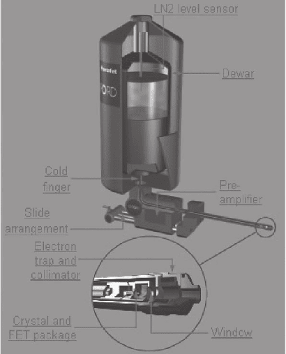
Figure 4–19. Schemat-
ics of a commercial
EDXS detector showing
the detector front, the
Dewar system to cool
the detector, and various
components that are
interfaced in the elec-
tron microscope. (Cour-
tesy of N. Rowlands,
Oxford Instruments.)
(See color plate.)
294 G. Botton
pairs through photoelectric effect. When this process occurs in an
electric fi eld, a current pulse is generated and subsequently measured
by low-noise electronic components. Detectors based on Si are more
commonly used in AEM because of the lower cost than Ge-based
detectors (described below). Due to the fact that very high purity Si
crystals are not available, Li additions in Si are used to compensate for
residual impurity dopants that would create undesirable recombina-
tion sites for electronhole pairs and uncharacteristic current related to
the existence of impurity-generated acceptor levels (thus holes in the
valence band). The Li role in the so-called Si(Li) detectors is therefore
to effectively create an intrinsic semiconductor region where e–h pairs
generated by the incident photons produce a current fl ow that can be
measured. Incident photons generate e–h pairs at the rate of 1 pair/
3.8 eV. The number of e–h pairs generated in the “active layer” of the
detector is thus proportional to the incident photon energy (which is,
in turn, related to the energy level involved in the transitions following
ionization of the atom by the incident electron beam). For Ge detectors,
high-purity crystals can be obtained and Li additions are not
necessary.
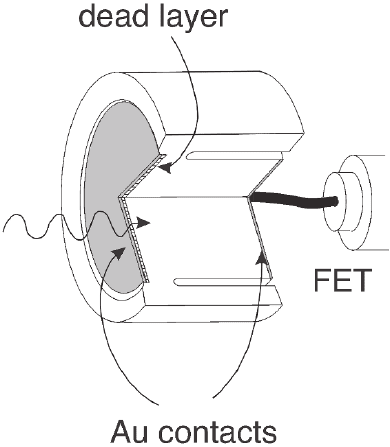
The electric fi eld in the detector necessary to cause the current fl ow
is generated by metallic contacts (Au) (Figure 4–20) on the front and
back surfaces of the crystals (typically 3 mm thick) and the application
of a bias (0.5–1 kV) between the front and back of the detector with
electrons traveling to the positive electrode and holes to the negative
electrode. Some loss of charges occurs, however, in proximity of the
contacts due to recombination in the charges near the metallic contact
(about 200 nm in width). These regions are typically referred to as
“dead-layers” in the literature as they do not contribute to the genera-
tion of signal and transfer of charge. The thickness of the crystal is
normally large enough to convert all the photons to e–h pairs but for
Figure 4–20. Diagram of
an EDXS detector demon-
strating the various ele-
ments of the detector
contacts, the dead layer,
and the preamplifi er.
(Adapted from Woldseth,
1973.)
