Hawkes P.W., Spence J.C.H. (Eds.) Science of Microscopy. V.1 and 2
Подождите немного. Документ загружается.

Chapter 4 Analytical Electron Microscopy 275
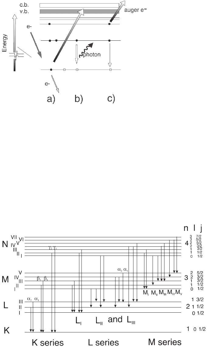
part of the spectrum) or Auger electrons. The energy of these X-rays,
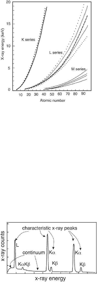
typically in the range of few hundred electronvolts to 20–40 keV, is also
characteristic of the energy differences between the levels involved in
the excitation and deexcitation process (Figures 4–4 and 4–5). Because
various energy shells can be excited, peaks in the spectra are labeled
according to the corresponding quantum levels involved in the transi-
tions based on the nomenclature illustrated in Figure 4–4. The depen-
dence on characteristic energy levels of the bound electrons makes it
possible to identify the atomic number of the elements that have been
involved in the excitation process. However, not all transitions between
Figure 4–3. Energy level diagrams showing the transitions required for
the generation of X-rays and Auger electrons following the excitation of core
electrons by the primary incident electrons.
Figure 4–4. Detailed energy levels, their associated quantum number n, l, and j, and associated
families with the transitions respecting the selection rules described in the text.
276 G. Botton
the energy levels are allowed: there must be a change in the angular
momentum quantum numbers 艎 and j for transitions to be observed
according to the rule ∆艎 = ±1, ∆j = −1, 0, +1 (Figure 4–4). The probability
of these excitations and generation of X-rays or Auger electrons varies
with atomic number based on cross sections and fl uorescence yield.
The effi ciency of the detection of the X-rays also varies according to
their energy due to absorption in the detector material. In addition, the
X-rays generated can be absorbed in the sample itself before reaching
the detector. The spectrum itself consists of the characteristic X-ray
peaks for the excited atoms present in the sample superimposed on a
continuum noncharacteristic background (Figure 4–6).
To relate the intensity detected in spectra to the concentration of the
elements, several effects must therefore be considered: the intensity of
the peaks in the spectra must be corrected using cross sections and
fl uorescence corrections and absorption in the sample and in the detec-
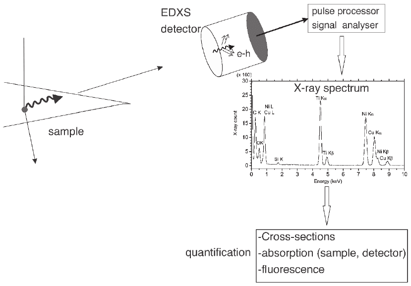
tor. Figure 4–7 summarizes the process of signal generation, collection,
display, and quantifi cation in a fl ow chart containing various steps of
signal correction. Based on the quantifi cation of signals, it is possible
Figure 4–5. Characteristic
X-ray energy for different
families of lines as a func-
tion of atomic number.
Figure 4–6. EDS spec-
trum demonstrating
the characteristic lines
(with energies pre-
sented in Figure 4–5)
and the continuum
background.
Chapter 4 Analytical Electron Microscopy 277
to measure the local concentration to an accuracy limited by the statis-
tic uncertainty of the spectrum and the errors in the cross sections.
Due to the limited signal collection effi ciency of the detector, the
fi nite acquisition time and the presence of a noncharacteristic back-
ground under the element-specifi c peaks, the technique is generally
not suitable for the detection of trace elements in samples but it can
provide rapid quantitative data on elements to within a few atomic
percent accuracy, with detection limits typically of a few percent.
Improvements in collection effi ciency and long acquisition times,
however, have led to detection limits of fractions of 1% (see Section 7
of this chapter).
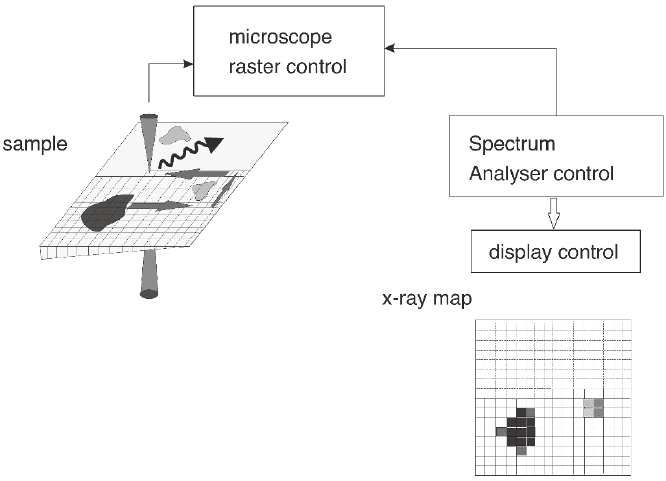
Using software that can control the electron beam position on the
sample and the data collection in a sequential manner, generated
signals can be collected over an area of the sample so that the intensity
of characteristic signals, as a function of position, represents the local
composition variations in the sample as displayed in an elemental map
(Figure 4–8). Further processing of spatially resolved spectra can also
be carried out so that quantitative maps and statistical analysis of the
concentration and element distribution can be displayed. Details of the
performance and limitations of EDXS as well as the approaches used
to quantify the data are given in subsequent sections.
Figure 4–7. Schematic diagram for the generation of X-rays in the sample, detection of the X-rays in
the detector (by generation of electron and hole pairs), pulse analysis, and quantifi cation process of
the spectrum to derive the composition of the sample. Detailed procedures of quantifi cation are
described in Section 4.
278 G. Botton
1.2 Overview of Electron Energy Loss Spectroscopy
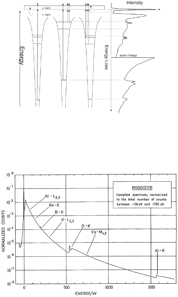
EELS is based on the measurement of the energy that the primary
incident electrons have lost while causing various inelastic processes
in the sample. The excitation of electrons from core energy levels that
precedes the generation of X-rays or Auger electrons is only one of the
mechanisms by which the primary electrons can lose some of their
energy. For this particular case, the energy loss process gives rise to
signals known as “core edges” with characteristic energies closely
related to the binding energy of the excited electrons (Figure 4–9) in
the atoms. Excitation of valence electrons into the conduction band and
collective excitation of weakly bound electrons are also potential energy
loss processes (Figure 4–9) called plasmons. These losses contribute to
the low loss part of the spectrum (Figure 4–10) from a few to about
50–100 eV. Although characteristic core edges can appear at relatively
low energies, strong low-loss signals contain information about the
materials dielectric properties. With reference spectra and databases,
it is therefore possible to identify particular compounds based on the
shape of the low-loss spectrum. Identifi cation of the chemical state and
the compound is also possible through the analysis of fi ne modulations
appearing in the fi rst few electronvolts from the core edges threshold.
These modulations are known as electron energy loss near-edge struc-
ture (ELNES) and contain information about the electronic structure
and bonding environment of the excited atom. This information is now
frequently used in the study of electronic structure and chemical state
Figure 4–8. Schematic diagram describing the processes necessary to record an elemental map with
EDXS. The synchronous scan of the beam is associated with a pixel position where the recording of
the signal takes place. The peak intensity is measured for each element at each pixel position and is
plotted in a two-dimensional elemental map.
Chapter 4 Analytical Electron Microscopy 279
Figure 4–9. Schematic diagram of the associated features in a spectrum. The core edges arise from
transitions from deep core levels to the fi rst unoccupied states above the valence band (and Fermi
energy) and the continuum. Excitation from defect states in the gap are also shown as well as collective
excitations of valence electrons giving rise to broad features called plasmon peaks.
Figure 4–10. Full energy loss spectrum recorded over a large energy range demonstrating the large
dynamic range of the recorded intensities and the relative intensity of core losses as compared with
the background. (Courtesy of H. Sauer, Fritz-Haber Institut/MPG, Berlin.)
280 G. Botton
of materials with applications ranging from semiconductor devices to
the study of minerals whereas low-loss structures have been used in
the study as diverse as biological structures to superconductors.
Similar to the case of EDXS microanalysis, the intensity of core edges
is related to the probability of excitation and thus to cross-section
values and the concentration of elements. The intensity of edges rela-
tive to the background, however, is strongly dependent on the thick-
ness of the analyzed area and edges can remain simply undetected
in the case of thick samples. As in the case of EDXS analysis, this
technique is not ideal for routine detection of trace elements due to
the very intense background typically dominating the signal at the
edges and the overall small recorded signal of edges with respect to
the total recorded signal (Figure 4–10), although acquisition conditions
can be optimized for the detection of minor constituents (discussed in
Section 7.1) .
EELS signals offer the advantage of being generated by a primary
event: the loss of energy. As compared to EDXS, the intensity of recorded
signals is therefore not linked to the secondary process of fl uorescence
resulting in the deexcitation via X-ray emission. For light elements such
as O, N, C, B, this is a remarkable advantage because the fl uorescence
yield (the probability of X-ray relative to Auger electrons generation,
see Section 4.1) decreases by orders of magnitude as compared to
higher atomic number elements such as transition metals. Therefore,
EELS analysis is generally considered to be more appropriate for the
detection of light elements than EDXS analysis.
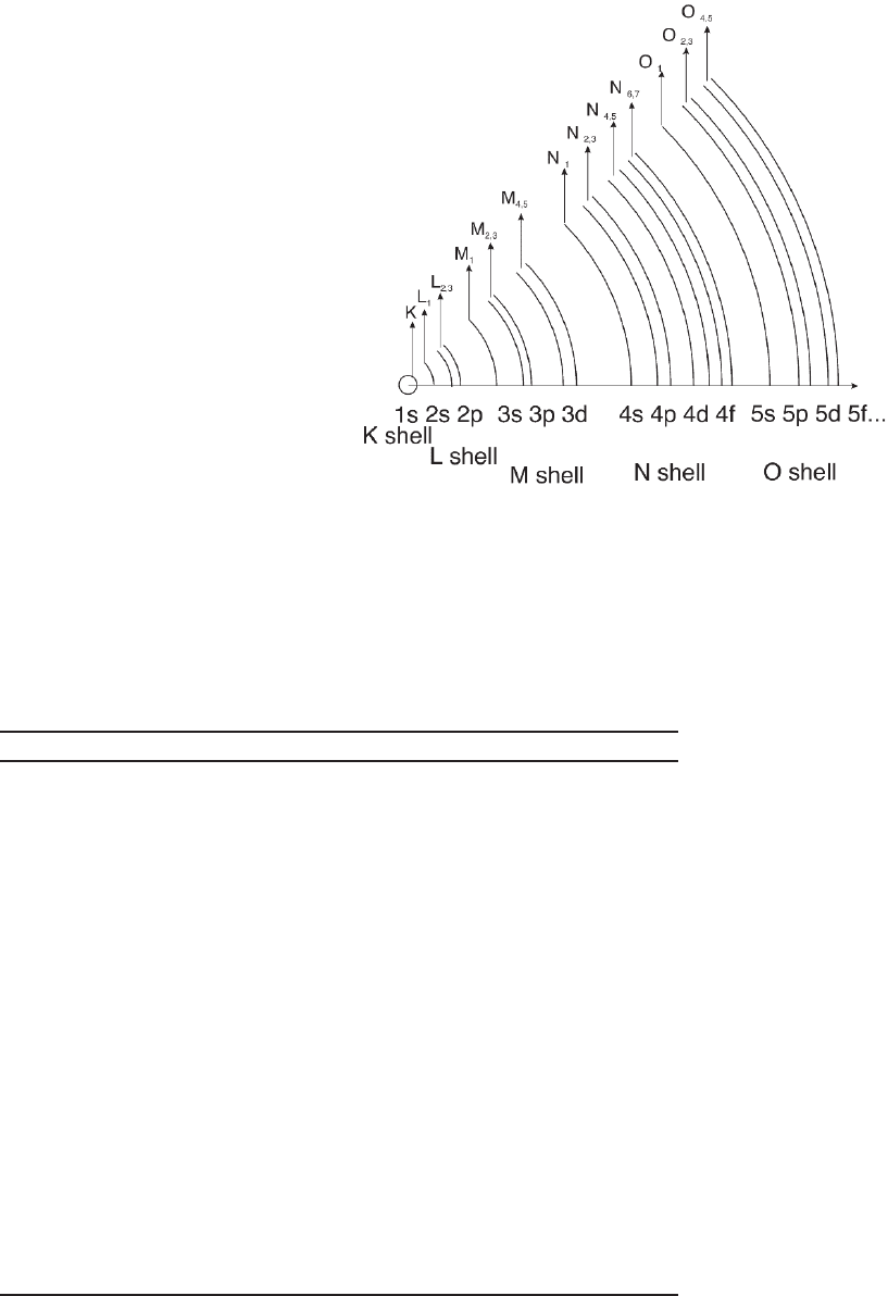
The core edges can be identifi ed and labeled according to the energy
levels of the ejected electron and the respective quantum numbers. K,
L, M, N, O edges are related to the transitions involving n = 1, 2, 3, 4,
5 principal quantum numbers, respectively. The angular momentum
quantum numbers 艎 (s,p,d,f) and j lead to sublabels as indicated in
Figure 4–11. A summary of the information that can be retrieved from
EELS spectra is shown in Table 4–1 (Colliex, 1996).
The collection of EELS spectra is carried out with an energy loss
spectrometer either attached at the bottom of the TEM column (post-
column fi lter) or within the projector lens system (in-column fi lter)
(Section 2.4.1). In both cases, the electron energy distribution is ana-
lyzed with one or a series of dispersing elements that separate the
electrons according to their energy. The dispersion will result in the
generation of a spectrum that will be recorded on a detector system.
Depending on the fi lter electron optical confi guration and detector
system, spectra, images and diffraction patterns corresponding to spe-
cifi c energy losses can be recorded as discussed in Section 2.4.1. When
images or diffraction patterns are obtained using electrons with spe-
cifi c energy losses or with electrons having lost no energy, the tech-
nique is called energy-fi ltered microscopy.
1.3 Comparison with Other Spectroscopies
EDXS and EELS offer information complementary to other techniques
that yield compositional or spectroscopic data typically available in
Chapter 4 Analytical Electron Microscopy 281
surface analysis instruments such as X-ray photoelectron spectroscopy
(XPS), Auger spectroscopy, X-ray absorption spectroscopy, inverse pho-
toemission, etc. XPS provides information on the binding energy (E
b
)
of electrons in atomic core levels as ejected by incident photons. These
photoelectrons with kinetic energy E
k
are detected in vacuum as they
Figure 4–11. Diagram demonstrating
the origin of the spectroscopic labels
of energy loss spectra and the associ-
ated core levels. (Adapted from EELS
Atlas, C.C. Ahn and O.L. Krivanek.)
Table 4 –1. Information from EELS spectra.
Spectral region Type of information Application
Full spectrum Thickness, inelastic All analytical methods of
mean free path quantifi cation, volume
fraction
Low-loss Average electron Microanalysis of alloys, H
density content, identifi cation of
phases
Low-loss Joint density of states Optical properties of solids,
electronic structure,
correlation effects,
bandgap measurement
Low-loss Dielectric Relativistic effects, interface
properties/interfaces excitation effects/modes
Core-loss Edges intensity Quantifi cation of
concentration of elements
Core-loss Near edge structures Chemical state, coordination,
ionicity/valence, phase
identifi cation
Core-loss Extended fi ne structure Determination of radial
distribution functions
Core-loss White lines: density of Formal charge, charge
holes in the d-band transfer
282 G. Botton
escape the sample surfaces and the system workfunction (φ). This
process typically detects photoelectrons with very low kinetic energy
as the incident X-rays photons (E
v
) are typically a few kiloelectronvolts
and E
k
= E
v
− (E
b
+ φ). The technique thus provides essentially informa-
tion from the topmost few atomic layers and is used to analyze ultra-
thin layers and quantify composition of thin fi lms deposited on
surfaces, surface contaminants etc. Although the lateral resolution is
typically about a few tens of micrometers in commercial instruments,
near micrometer resolution can be achieved in synchrotron facilities
and in imaging XPS instruments. Using ion beams to sputter the
sample surface, depth profi ling can be carried out with a depth resolu-
tion of 2–5 nm due to the (energy-dependent) escape depth of the elec-
trons and, when sputtering is used, the ballistic mixing induced by the
incident ions. Angular resolved XPS methods can reach a depth resolu-
tion of about 1–2 nm as the escape angle can be tuned with the
spectrometer. The technique can therefore provide information on the
composition of surface layers and changes in the chemical state of
atoms as refl ected in the changes in binding energy.
In Auger spectroscopy, the energy of the Auger electrons typically
ranges from a few tens of electronvolts to 1–2 keV and, as in the case
of XPS, the escape depth from the sample surface is also limited to the
topmost few nanometers. The Auger electron energy between energy
levels A (initial core level) and levels B and C (secondary levels) (Figure
4–3) is determined by the energy levels involved in the transition as
E
ABC
= E
A
− E
B
− E
C
− φ. The changes in bonding due to changes in oxi-
dation state or structure are therefore refl ected in the energy of Auger
peaks as the energy levels would be affected by the changes in bonding.
The technique therefore provides both information on the elemental
composition and the chemical state.
X-Ray absorption spectroscopy provides information on the absorp-
tion process of incident photons caused by transitions from inner-shell
energy levels to the unoccupied states just above the Fermi energy and
the continuum free states. The technique is therefore complementary
to EELS as unoccupied states are probed but it offers the advantage of
giving access to higher energy edges and the possibility of analysis in
a controlled nonvacuum environment. With zone plate focusing of
incident photons in third-generation synchrotrons, it is possible to
obtain spot sizes of 15–30 nm. The X-ray absorption process can be
directly observed in transmission mode or via indirect yield of elec-
trons generated via the absorption process (total electron yield or
fl uorescence yield). In the latter case, the technique becomes surface
sensitive as the escape depth of detected electrons is limited by their
energy. Detection of elements in ppm concentration is possible due to
the low background of edges as compared to EELS.
As compared with these spectroscopic techniques, EDXS, carried out
with typical commercial detectors, can be considered a “bulk” analysis
technique yielding elemental information through the thickness of the
thin TEM foil with practically no content on the chemical state of the
detected elements. EELS in the analytical microscope also provides
information on the chemical composition through the thin foil thick-

Chapter 4 Analytical Electron Microscopy 283
ness, but offers the clear advantage of providing spectroscopic infor-
mation on the chemical state.
Table 4–2 summarizes the general applications of the techniques,
limitations, resolution, etc. Characteristic details on resolution vary
depending on the acquisition conditions, energy of the elements of
interest, and effi ciency of the detection system.
2 Instrumentation
The ultimate aims of AEM are to analyze materials with high spatial
resolution. These goals require the use of electrons source and electron
optic components capable of producing intense beam currents into
small electron probes, and detectors to collect the various analytical
signals generated from the interaction of incident electrons with atoms
in the solid. These requirements are met in a TEM confi gured for ana-
lytical work offering bright electron sources, fl exible condensing optics,
clean vacuum, and a range of detectors for imaging and spectroscopy.
Thin and very clean samples are a necessity for achieving the ultimate
performance expected from the high-spatial resolution techniques and
these are as important as the quality of the microscope.
2.1 Electron Sources and Probes
TEMs for conventional TEM, high-resolution TEM, and AEMs can be
equipped with two types of electron sources—thermionic and fi eld
emission. Thermionic sources such as W hairpin fi laments and refrac-
tory crystals such as LaB
6
operate at high temperature and emit elec-
trons that are subsequently accelerated by the anode potential
(100–200 kV or more). The thermionic sources are heated either by a
fl ow of current through the emitting material itself (for the W hairpin
cathode fi lament) or by thermal contact of a low-workfunction emittor
material such as LaB
6
and resistive heating of a W wire supporting
material. The fi eld-emission gun (FEG) source operates on the princi-
ples of electron tunneling from the tip to vacuum following the appli-
cation of a strong electric fi eld (≈10
9
V/m) generati ng a very large electric
fi eld gradient at the tip of the cathode. This high fi eld results in a very
narrow potential barrier allowing tunneling of the electrons from a
low-workfunction metallic tip to vacuum. This emission is generated
Table 4 –2. Comparison of spectroscopy techniques.
Lateral
resolution Depth Detection Elemental Spectroscopic
Tech nique limits resolution limit information information
EDXS 1–2 nm No Minor Yes No
EELS 0.5–1 nm No Minor Yes Yes
Auger 10–50 nm Yes (2–5 nm) Minor Yes Yes
XPS 1–10 um Yes (1–5 nm) Minor Yes Yes
XAS 20–100 nm No Trace Yes Yes

284 G. Botton
from a very small area (in the order of 10 nm or less) of a single crystal
tip resulting in high current density. There are variants to this gun
confi guration. Cold FEGs emit at room temperature and have the dis-
advantage of requiring ultrahigh vacuum (10
−8
–10
−9
Pa) to prevent the
adsorption of gas molecules on the surface of the tip. This leads to
a reduction of the emission current and to instabilities caused by
an increase of the workfunction due to the surface contaminants. To
reduce this sensitivity to adsorption, thermally assisted fi eld emission
and Schottky emission sources have been introduced. Thermally
assisted FEGs are based on the application of a high electric fi eld to W
single crystal tips heated to about 1600 K. The emission also occurs
through tunneling from a small area of the tip and the characteristics
are similar to cold fi eld emission. The benefi ts of high temperature
operation is the increased stability due to a cleaner tip at the expense
of a higher energy spread of the emitted electrons as compared to cold
FEG. The last type of source also considered in the class of FEGs is the
Schottky gun. These guns are based on the Schottky emission principle
that causes a reduction of the energy barrier for simple thermionic
emission with a combination of electron image forces and strong elec-
tric fi elds applied to the tip (e.g., see Reimer, 1984; Solymar and Walsh,
2004). Strictly speaking, the emission is therefore not due to tunneling
as it combines thermal emission with high electric fi elds. Due to the
high coherence and brightness, however, Schottky sources are also
considered in the class of fi eld emission sources. To further decrease
the workfunction, the W tip is generally coated with ZrO to increase
the emission current. Optimal current stability is obtained with W
crystals oriented so as to expose (100) crystalline facets and ZrO coating.
The high operating temperature reduces the sensitivity to adsorption
but it has the drawback that the material is sensitive to reactions with
the gases present in the gun area. Ultrahigh vacuum is therefore
required but at less strict levels than what is necessary for cold FEG.
High current densities can be achieved with Schottky sources due to
the very small emission area. High total emission currents can also be
generated by controlling the extraction voltage and the gun lens opera-
tion parameters. In some implementations of the Schottky guns, total
beam currents in the order of 100–300 nA can be achieved.
The previous description has been very qualitative and further ana-
lysis is required to effectively compare the performance of the various
types of sources and understand the requirements for AEM. A key
quantity characterizing the gun performance is the brightness of the
source B defi ned as the current per unit area and solid angle
B
i
d
i
d
=
(
)
=
()
ee
ππαπα2
4
2
2
2
(1)
where i
e
is the current emission, d is the beam diameter, α is the con-
vergence angle of the cone containing the electrons, and πα
2
is the solid
angle corresponding to the cone. The units of B are A/(m
2
sr) and the
values scale with the accelerating voltage (B values are typically given
at 100 keV) and are maintained throughout the optical system (from
the emission source to the sample).
