Hammond C. The Basics of Crystallography and Diffraction
Подождите немного. Документ загружается.

284 Electron diffraction and its applications
Incident beam
Distribution of
inelastic scattered
intensity within
specimen
Intensity distribution
around incident
beam
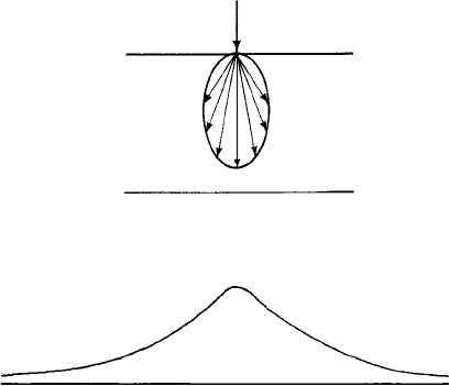
Fig. 11.8. The distribution of inelastic scattered intensity within a specimen and (below) the
distribution intensity around the incident (unscattered) electron beam.
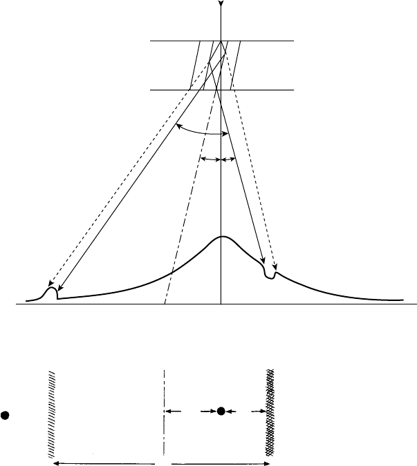
than the Bragg angle (Fig. 11.9(a)). No reflection of the incident beam, or given the
extension of the reciprocal lattice point (Section 11.2), only a weak reflection of the
incident beam occurs. However, those inelastically scattered beams which are incident
to the planes at the Bragg angle are reflected. Figure 11.9(a) shows two such beams, AB
and AC, AB being more intense than AC since the inelastic scattering angle is smaller.
Beam AB is reflected to D (solid line), giving an increase in intensity; at the same time it
is attenuated in the direction to E (dotted line) giving a reduction in intensity. A similar
reflection (solid line) and attenuation (dotted line) occurs for AC. However, because
beam AC is weaker the overall effect will still be an increase in intensity at D and a
decrease in intensity at E. Now these peaks are not spots but are sections through cones
of intensity which intersect the reflecting sphere to give nearly straight lines running
parallel to the reflecting planes, i.e. perpendicular to the plane of the paper. These—the
‘light’ and ‘dark’ Kikuchi lines—are shown in the plane of the diffraction pattern in
Fig. 11.9(b). Also shown is the (weak) hkl diffraction spot and the downwards projected
trace of the planes which lies half-way in between the Kikuchi lines (dashed line). The
angle between the Kikuchi lines is 2θ and thus they have the same separation R as the
distance between the centre spot and hkl diffraction spot.
From Fig. 11.9(a) two angles are of interest; φ, the deviation of the planes from the
exact Bragg angle, and ρ, the deviation of the planes from exact parallelism with the
incident beam. There angles may be determined by measuring the distance a
K
(from the
dark Kikuchi line to the centre spot) and a
t
(from the trace of the planes and the centre
spot). Given the camera length L (Fig. 11.4), then φ = a
K
/L and ρ = a
t
/L.
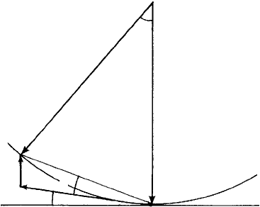
The geometry may also be represented in terms of the Ewald reflecting sphere con-
struction, Fig. 11.10. k and k
0
are the vectors representing the directions of the diffracted
11.5 Kikuchi and electron backscattered diffraction patterns 285
Light
Kikuchi
line
(a)
(b)
Trace of
reflecting
planes
D
E
A
C
B
Incident beam
2u
f
r
R
a
t
a
k
hkl
Dark
Kikuchi
line
Fig. 11.9. (a) A crystal with a set of planes at an angle to the incident beam slightly smaller than the
Bragg angle. AB and AC show two inelastically scattered beams (see Fig. 11.8) which are incident to
the planes at the Bragg angle and which are partly reflected (solid lines) and partly attenuated (dotted
lines) resulting in light (electron excess) and dark (electron deficient) Kikuchi lines, shown in plan in
(b) together with the diffraction and centre spots and the projected trace of the reflecting planes.
and direct beams and g
hkl
≡ d
∗
hkl
is the reciprocal lattice vector for the reflecting planes
(see footnote, page 198, Section 8.3). The hkl reciprocal lattice point lies outside the
sphere and the vector s (closely parallel to k and k
0
) represents the deviation of g
hkl
from
the exact Bragg condition, the modulus of which is given by
|
s
|
= φ
|
g
hkl
|
. Now we see
the value of Kikuchi lines in establishing the precise orientation of the reflecting planes:
as we (say) rotate the crystal clockwise, the pair of Kikuchi lines move to the left and at
the exact Bragg angle
(
φ = 0
)
, the dark Kikuchi line passes through the centre spot and
the bright Kikuchi line passes through the diffraction spot. Similarly, when the crystal is
286 Electron diffraction and its applications
s
k
2u
k
0
r
g
hkl
f
Fig. 11.10. The Ewald reflecting sphere construction for a set of hkl planes at an angle to the incident
beam (vector k
o
) slightly smaller than the Bragg angle. The reciprocal lattice vector g
hkl
lies outside
the sphere and the vector s represents the deviation from the exact Bragg condition. φ is the deviation
angle of the planes from the exact Bragg angle and ρ the deviation of the planes from exact parallelism
with the incident beam.
rotated such that the planes are exactly parallel to the incident beam, the Kikuchi lines
will be at equal distances each side of the centre spot.
3
In practice we may see many Kikuchi lines—as many pairs as there are diffraction
spots (Fig. 11.11). However, just two pairs of lines, and two diffraction spots, are
sufficient to determine the orientation of the crystal with respect to the incident electron
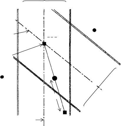
beam direction. Figure 11.12 shows a pattern with two spots, h
1
k
1
l
1
and h
2
k
2
l
2
and
their associated Kikuchi lines; half way in between which are drawn the downwards
projected traces of the planes (dashed lines). The downwards direction of the zone axis
[¯u¯v ¯w] lies at the intersection of the traces as shown; the upwards direction [uvw] (i.e.
anti-parallel to the electron beam) lies on the opposite side of the centre spot and is found
by cross-multiplication of the indices as described in the footnote on p. 281. The angle
η between [uvw] and the centre spot, 000, is simply found by measuring the distance P,
again using the relationship η = P/L.
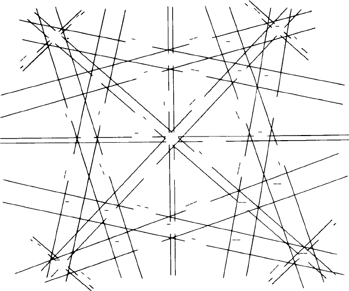
The pattern of Kikuchi lines also reflects the symmetry of planes in a crystal and
‘maps’ may be created showing the patterns of lines for different crystal orientations.
Figure 11.13 shows one such map for an fcc crystal centered on [001], the four-fold
symmetry of which is clearly evident. Note that the spacings of the pairs of lines corre-
spond to the reciprocal lattice spacings; 200 and 020 passing through the centre being
the narrowest, then 220, 2
¯
20, and so on. The value of such maps is that they provide
a means of tilting the specimen into any desired orientation: one simply ‘moves along’
a pair of lines (like railway lines!) to bring the desired zone axis to the centre of the
projection.
3
In this situation the (simplified) explanation of Kikuchi line contrast given above breaks down. A more
detailed analysis shows that the lines are still observed.

11.5 Kikuchi and electron backscattered diffraction patterns 287
Fig. 11.11. An electron diffraction pattern of an austenitic stainless steel (fcc) showing diffraction
spots and Kikuchi lines. (Photograph by courtesy of Dr P.M. Champness and Professor G.W. Lorimer.)
11.5.2 Electron backscattered diffraction (EBSD) patterns
in the SEM
The geometry of the formation of EBSD patterns is analogous to that of Kikuchi patterns
except that the incident electron beam is at a small angle, typically ∼20
◦
, to the specimen
surface. Only those electrons inelastically-elastically scattered from depths some 10–
20 nm below the specimen surface (depending on the specimen, incident beam energy
and angle) emerge from the specimen to be recorded on a phosphor screen and a CCD
camera. Hence EBSD is essentially a surface technique and any surface damage or
distortion must be removed by careful preparation techniques. An example of an EBSD
pattern is shown in Fig. 11.14. The orientation analysis is of course carried out by
computer software. The great value of EBSD is that it can be used to determine the
orientations of crystals in a specimen and therefore the misorientations and nature of
the boundaries between them. The beam is scanned across the specimen surface and the
crystal orientation is measured at each point—the resulting map reveals the constituent
crystal morphology, orientations and boundaries. The resolution depends of course on
the diameter of the incident beam and interaction volume—at present, under favourable
conditions, resolutions of 10–20 nm are obtainable. The crystal orientations may also
be presented in the form of a pole figure in an analogous way to the X-ray pole figures
described in Section 12.5.3. They are in fact complementary techniques: X-rays record
288 Electron diffraction and its applications
Zone axis
antiparallel to
electron beam
Trace
h
2
k
2
l
2
Trace
h
1
k
1
l
1
h
2
k
2
l
2
h
1
k
1
l
1
000
P
[uvw]
[u vw]
Light
Intersection
of traces, zone
axis parallel
to electron beam
Dark
Kikuchi lines h
2
k
2
l
2
Light
Dark
Kikuchi lines h
1
k
1
l
1
Fig. 11.12. Determination of the exact orientation of a crystal from a spot-Kikuchi line electron
diffraction pattern. The downwards zone axis, [¯u¯v ¯w], lies at the intersection of the projected traces of
the reflecting planes h
1
k
1
l
1
and h
2
k
2
l
2
. The angle η of the zone axis [uvw] to the incident beam direction
is given by η = P/L.
the reflections non-sequentially from one set of planes in a larger volume (area and depth)
of the specimen.
EBSD is also complementary to the Laue X-ray diffraction technique (Section 9.4);
again in the X-ray technique the X-rays penetrate into a much greater depth in the
specimen (typically 5–20 μm) compared to the 10–20 nm of EBSD.
11.6 Image formation and resolution in the TEM
TheAbbe criterion for image formation, discussed in Section 7.5, applies equally to light
and electron microscopy. Electron wavelengths are very much smaller (4 pm for 100 kV
instruments) than atomic dimensions, but atomic resolution (perhaps the ultimate goal in
microscopy) is limited by the severe spherical aberration of electron (electromagnetic)
lenses which limits numerical aperture (NA) values to the order of 0.01. Using the
equation a = 0.5λ/NA gives a limit of resolution of 2Å—a dimension of the same
order as atomic dimensions and interatomic spacings. The development of higher kV
instruments (smaller λ) and improvements to the corrections (for spherical aberration and
11.6 Image formation and resolution in the TEM 289
103
215
114
125
112
200
020
220
001
013
215
131
111
311
200
103
220
125
114
114
125
112
215
111
311
131
131
215
311
112
220
020
131
111
114
125
013
311
111
112
311
131
220
311
131
131
111
111
111
311
311
131
111
Fig. 11.13. A Kikuchi ‘map’ for an fcc crystal centered on [001]; note the four-fold symmetry and the
relative spacings of the pairs of lines. Tilting the crystal ‘along’ a pair of Kikuchi lines enables other
zone axes to be brought to the centre of the projection (Map by courtesy of Prof. M. H. Loretto.)
astigmatism) in electron lenses have reduced this limit to about 1 Å. However, to obtain
such Abbe or high resolution images is not a simple matter—neither experimentally nor
theoretically. First the specimen must be very thin (of the order 2–20 nm) in order that
the inelastic scattering processes described in Section 11.5 are negligible. Second, the
specimen must be carefully orientated such that the electron beam is precisely parallel
to a prominent zone axis—and of course there are no Kikuchi lines to help guide us!
Under such conditions several diffracted beams are excited which then pass through
the objective aperture to interfere to form the image. However, there is never an exact
one-to-one correspondence between the atomic structure in the specimen and the image,
the contrast of which depends upon the amount of defocus of the objective lens and the
fact that higher-angle reflections are excluded by the objective aperture and which would
otherwise refine the fine detail in the image. Hence, it is standard practice to compare
the observed images (obtained at different amounts of defocus) with those obtained by
computer simulation. However, despite these problems ‘high resolution’ TEM images

290 Electron diffraction and its applications
Fig. 11.14. An EBSD pattern of a β (bcc) titanium alloy, a 111 zone axis is at the lower right hand
corner. (Photograph by courtesy of Dr E. Merson.)
1 nm
Fig. 11.15. Ahigh resolution TEM‘dumbbell’image of germanium; the electron beam is aligned along
a 110direction in the crystal (diamond-cubic structure). (Photograph by courtesy of TEAM, a collabo-
rative programme between Argonne National Laboratory, CEOS, FEI Company, Frederick Seitz Mate-
rials Laboratory, Lawrence Berkeley National Laboratory’s National Center for Electron Microscopy,
Oak Ridge National Laboratory. TEAM homepage: http://ncem.lbl.gov/TEAM-project/index.html.
are being routinely obtained in which the peaks of intensity clearly correspond to atom
positions. Figure 11.15 shows such a high resolution TEM of germanium which has the
diamond cubic structure (Fig. 1.36(a)). The electron beam is aligned precisely along
a 110 direction in the crystal and in this orientation the germanium atoms appear to
be arranged in pairs—the so-called ‘dumbbell’ structure. So, here we see atoms: how
delighted Robert Hooke would have been to actually see his ‘bullets’ (Fig. 1.1 in this
book).
11.6 Image formation and resolution in the TEM 291
There are, however, other, no less important, modes of image formation available
in the electron microscope which occur when only one beam—either the direct beam
(bright field mode) or one diffracted beam (dark field mode) passes through an objective
aperture of small numerical aperture. In the bright field mode the contrast arises from
the varying attenuation of the direct beam through different regions of the specimen; the
attenuation arisingas a result eitherof inelastic or ofelastic scattering (or moregenerallya
combination of the two). The former case gives rise to mass-thickness contrast because
the amount of inelastic scattering depends on the thickness of the specimen and the
variations in atomic number and density of the various atomic species present. The latter
case gives rise to diffraction contrast which arises from variations in elastic scattering,
or Bragg reflection, of the incident beam. The subject is not simple because, as noted on
p. 206 (Section 9.1) we have to take account of the dynamical interactions between the
direct and reflected, re-reflected, etc. beams. The result of these interactions is a ‘to-and-
fro’ or pendulum-type swing of energy between the direct and diffracted beams as they
progress down through the specimen, the periodicity of which is called the extinction
distance. Hence the tapered edges of specimens, or inclined grain boundaries, show light
and dark ‘thickness’ fringes corresponding to the depths at which (in bright field mode)
the direct beam has a maximum or minimum intensity.
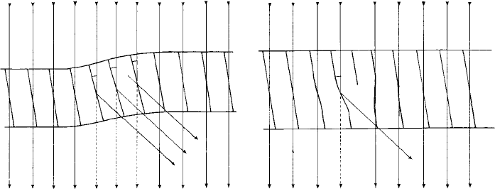
Diffractioncontrast may be illustrated by two simple examples. Figure 11.16(a)shows
a thin metal specimen which is slightly bent or distorted—a very common situation.
Hence the planes across the surface are at slightly different angles to the incident beam:
when they are close to, or at, the exact Bragg angle, reflection occurs and hence in
these regions the direct beam is attenuated. When the direct beam is used to form the
image (bright fieldmode) these regions result in diffuse, darklines called Bragg contours.
Correspondingly, when the diffracted beam is used to form the image the Bragg contours
appear bright. The contrast from crystal defects arises in a similar way. For example,
Fig. 11.16(b) shows an edge dislocation in a specimen; note that around the ‘extra’ half
plane the planes are bent or curved, the distortion decreasing further away from the
Bragg
contour
Dislocation
image
Incident beam(a) (b) Incident beam
u
u
u
u
Fig. 11.16. Diffraction contrast image formation. The origin of (a) Bragg contours in a slightly-bent
metal thin foil and (b) from the bending of planes around an edge dislocation.

292 Electron diffraction and its applications
dislocation. If the curvature is such as to bring the planes to the Bragg angle (as is shown
in Fig. 11.16(b)), reflection of the incident beam will occur and thus the dislocation is
imaged. Note that we do not image the dislocation as such, we only image, or record,
the bending of the planes one side, or the other, of the dislocation.
Exercises
11.1 Using de Broglie’s equation, derive a simple equation for the (non-relativistically corrected)
wavelength λ of electrons in the electron microscope in terms of m, e (electron mass
and charge) and V the microscope accelerating voltage. Given the following values of
m (rest mass) = 9.11 × 10
−31
kg, e (electron charge) = 1.6 × 10
−9
C, and h (Planck
constant) = 6.63 ×10
−34
Js, determine λ for V = 10 kV, l00 kV and 1 MV.
11.2 Figure 11.17 is an electron diffraction pattern of a thin crystal of aluminium (fcc, a =
0.4049 nm (4.049 Å)) taken using an electron microscope operating at l00 kV, and shows
diffraction spots from the ZOLZ (zero order Laue zone) only. Given theelectron wavelength
λ = 0.0037 nm (0.037 Å) and the camera length L = 688 mm, index the diffraction
spots and determine the zone axis of the diffraction pattern. (Note: In face-centred lattices,
reflections from the planes for which h, k and l are not all odd or all even integers are
forbidden.)
(Hint: Refer to Table A.6.2 listing the indices {hkl}and d-spacings of the allowed reflecting
planes. Determine the d
hkl
-spacings of the diffraction spots in the pattern (see Section 11.3)
Fig. 11.17. An electron diffraction pattern (ZOLZ) of a fcc crystal. The camera length L (adjusted for
the print size) is 688 mm (see Exercise 11.2).

Exercises 293
and hence, using the table, find their indices {hkl}. Using the addition rule in Section 6.5.2,
assign a consistent set of indices hkl to the diffraction spots and hence find their common
zone axis using the equation in Section 6.5.7.)
11.3 In an electron diffraction experiment the bcc crystal described in Exercises 9.1 and 9.2 is
irradiated in the [100] (or a
∗
) direction with an electron beam of wavelength 0.002 nm
(0.02 Å). Find the reciprocal lattice points which lie close to the sphere in the ZOLZ (zero
order Laue zone) and FOLZ (first order Laue zone).
(Hint: Using the same reciprocal lattice scale as in Exercises 9.1 and 9.2, it will be found
that a very large sheet of paper and very large compasses are needed to draw the complete
reflecting sphere! However, a sketch of the surface of the sphere near the origin will suffice.
In electron diffraction, sections of the reciprocal lattice perpendicular to the electron beam
(i.e. normal to the [100] or a
∗
) direction are most convenient. Draw the section through
the origin 000 containing the 0kl reciprocal lattice points (i.e. the ZOLZ), and the section
containing the 1kl reciprocal lattice points (i.e. the FOLZ) (see also Fig. 6.8(a)). Estimate
the regions of these reciprocal lattice sections, and hence the reciprocal lattice points, which
are close to the surface of the reflecting sphere.)
11.4 Figure 11.18 is an electron diffraction pattern of a particle which has been extracted from
a nitrided chromium-containing steel. It is one of three possible compounds, CrN, Fe
3
Cor
(Cr,Fe)
7
C
3
.Thed
hkl
-spacings and indices of the lowest angle reflections are given below.
4
Given λL = 38.3 Å mm, identify the compound and index the diffraction pattern.
Fig. 11.18. An electron diffraction pattern (ZOLZ) of a particle extracted from a nitrided chromium-
containing steel. The camera constant λL (adjusted for print size) is 38.3 Å mm (see Exercise 11.4).
4
Data for CrN from the ICDD Powder Data File (11–65), for Fe
3
C and (Cr,Fe)
7
C
3
from Interpretation of
Electron Diffraction Patterns, 2nd edn, 1972 by K. W. Andrews, D. J. Dyson and S. R. Keown, Adam Hilger
(1972).
