Hammond C. The Basics of Crystallography and Diffraction
Подождите немного. Документ загружается.


304 The stereographic projection and its uses
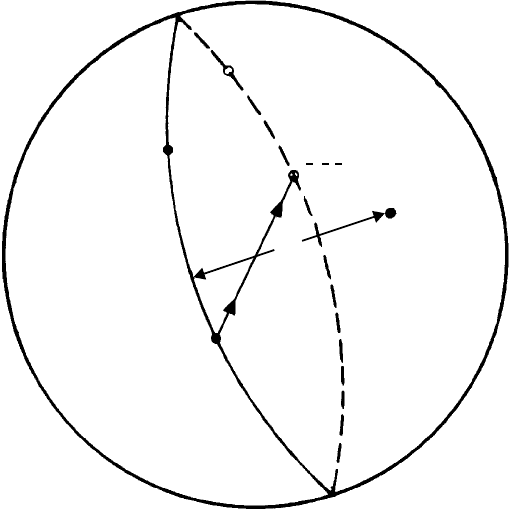
Fig. 12.8. The Wulff net (which may be rotated about the centre of the stereographic projection such
that the ‘axis’A...A lies in any direction).
line, symmetrical about the centre, is the continuation of the great circle in the southern
hemisphere and the angle, say, between h
2
k
2
l
2
and h
3
k
3
l
3
is found by continuing the
small-circle division-counting round the edge. The opposite direction of a plane normal,
say h
1
k
1
l
1
, is found by drawing a line through the centre (arrowed line in Fig. 12.9); the
two poles, h
1
k
1
l
1
and
¯
h
1
¯
k
1
¯
l
1
being related by a centre of symmetry. Finally, the zone
axis is the direction 90
◦
to all points in the zone as indicated by the point ZA.
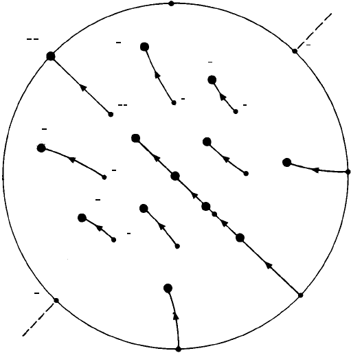
Small circles may be used to locate poles in the stereographic projection given their
α, β and γ angles to the x, y and z axes (Exercise 12.3). They may also be used to find
the positions of the poles when the crystal is rotated away from its ‘standard’orientation
(z axis along the north pole—Fig. 12.6) to some other orientation. Suppose we wish to
rotate the crystal to bring (112) to the centre. The angle of rotation (the angle between
(001) and (112)) is 35.3
◦
and the axis of rotation is the [1
¯
10] − [
¯
110] direction. The
Wulff net is orientated such that the small circles are centered along this axis (A...A,
Fig. 12.10) and all the poles rotated 35.3
◦
around their respective small circles, the angle
of rotation being calibrated by the intersections of the great circles.
12.4 Stereographic projections of non-cubic crystals 305
A
hkl
333
hkl
222
hkl
111
hkl
111
A
°09
Z
A
Fig. 12.9. Use of the Wulff net: to find the angle between two planes h
1
k
1
l
1
and h
2
k
2
l
2
in the northern
hemisphere, the Wulff net is rotated until the poles lie on the same great circle (solid line, axis along
A...A); the angle between the poles is calibrated by the intersections of the small circles. The dashed
line represents the continuation of this great circle in the southern hemisphere on which lies the pole
h
3
k
3
l
3
. The pole
¯
h
1
¯
k
1
¯
l
1
is related to h
1
k
1
l
1
by a centre of symmetry indicated by the arrowed line. ZA
indicates the zone axis of the zone in which all these poles lie.
12.4 Stereographic projections of non-cubic crystals
Stereographic projections of triclinic, monoclinic and trigonal crystals appear to be rather
complicated because the crystal axes in these systems are not orthogonal; we will not
consider them further. Stereographic projections of hexagonal crystals in the ‘standard’
orientation (i.e. the z-axis or (0001) in the centre and the x, y and u axes in the plane
of the projection) are, like those of cubic crystals, easily visualized—the hexagonal
symmetry of the pattern of poles is immediately evident. Similarly with orthorhombic
(and tetragonal) crystals, except that in these cases, as compared to cubic crystals, the
{110} planes are no longer at 45
◦
to the {100} planes; the angles must be calculated from
the a , b and c lattice parameters. Furthermore, as shown in Section 5.5, in non-cubic
crystals plane normals and directions with the same numerical indices are not, except in
special cases, parallel to each other. For example, in hexagonal crystals a plane normal
such as (10
¯
10) is parallel to the direction [10
¯
10] but a plane normal such as (10
¯
11) is
not parallel to the direction [10
¯
11]. In orthorhombic crystals a plane normal such as
(100) is parallel to the direction [100] but a plane normal such as (110) is not parallel
306 The stereographic projection and its uses
A
(110)
(100)
(110)
(010)
(110)
A
(111)
(011)
(101)
(111)
(101)
(111)
(011)
(001)
(011)
(111)
(111)
(100)
(101)
(101)
(111)
(112)
(110)
(011)
(112)
(001)
(111)
(010)
(111)
Fig. 12.10. A stereographic projection showing (i) poles of planes in the standard orientation (as in
Fig. 12.6) indicated by small dots and indices and (ii) their corresponding positions, indicated by large
dots and indices, with (112) rotated to the centre. All the poles rotate 35.3
◦
about small circles centered
on the ‘axis of rotation’A...A as indicated by the dashed lines.
to the direction [110] (see Fig. 5.5). This means that either two stereographic projections
are needed for non-cubic crystals, one showing plane normals and the other showing
directions, or a ‘composite’ stereographic projection is needed with the positions of
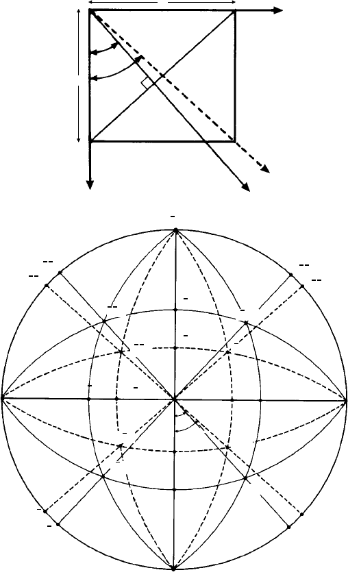
plane normals {hkl} and directions [uvw] clearly distinguished. Figure 12.11(a) shows
a plan view of an orthorhombic crystal (cementite, Fe
3
C; a = 4.524 Å, b = 5.088 Å,
c = 6.741 Å) perpendicular tothez axis and the angles α = tan
−1
a/b and ρ = tan
−1
b/a
of the (110) plane normal (full line) and the [110] direction (dashed line) to the x-axis
respectively. These poles, and those related by symmetry, are plotted on the ‘composite’
stereographic projection in Fig. 12.11(b). Similarly, the (101), [101], (011) and [011]
poles canalsobe plotted using theWulffnet given the ratiosof c/a andc/b. Havinglocated
these poles, the positions of the (111), [111] (and also higher-index) poles can be found
from the intersections of great circles as before—no further calculations are required.
In general, stereographic projections showing the positions of {hkl}plane normals are
more useful and where the indices are not bracketed (as in Fig. 12.6) it is understood that
they refer to plane normals, not directions. However, in non-cubic crystals a zone axis
located as shown in Fig. 12.9 should always be assigned square [uvw] brackets because
it will not in general coincide with the unbracketed indices which refer to plane normals.
12.5 Stereographic projections of non-cubic crystals 307
y
b
a
α
ρ
x
[110]
(110)
(a)
100
(110)
[110]
(101)
[1 0]1
(1 0)1
[101]
[011]
(011)
001
[011]
010
[1 ]10
(110)
100
[1 ]10
(110)
(101)
[101]
α
ρ
010
(b)
(111)
[1 ]11
[1 ]11
(111)
(111)
[1 ]11
(111)
[1 ]11
(011)
Fig. 12.11. (a) Plan view (perpendicular to the z axis) of an orthorhombic crystal (cementite, Fe
3
C)
showing the angles α and ρ = (90
◦
−α) of the (110) plane normal (full line) and [110] direction (dashed
line) to the x-axis respectively. (b) The ‘composite’ stereographic projection showing two sets of great
circles through the {hkl} poles (full lines) and the [uvw] directions (dashed lines).
308 The stereographic projection and its uses
12.5 Applications of the stereographic projection
12.5.1 Representation of point group symmetry
In Chapter 4 we discussed the point group symmetry elements—mirror planes, centres,
rotation and inversion axes of symmetry. We can represent the operation of these sym-
metry elements very easily with the stereographic projection by first placing a single
pole (representing a single face) in a general position in the projection (i.e. not on an
axis or mirror plane) and then seeing how it is repeated by the action of the symmetry
elements present. In this way all the 32 point groups can be built up.
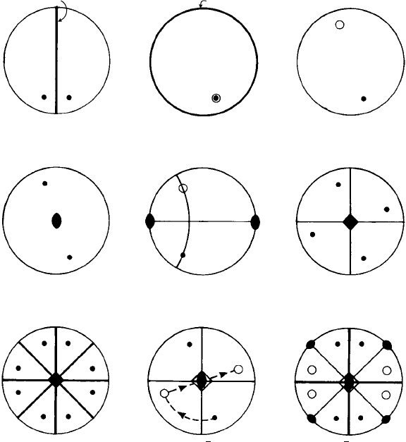
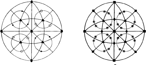
Figure 12.12(a) shows a pole reflected in a ‘vertical’ mirror plane m (indicated by a
heavy line) and Fig. 12.12(b) shows a pole reflected by a mirror plane in the plane of
the projection—one pole being in the ‘northern’ hemisphere and its reflection (an open
a ( )
m
b ( )
m
c (C of S)
d (2)
g (4 )
mm
h (4) i (42 )
m
e (2) f (4)
3
2
1
4
m
m
Fig. 12.12. Stereographic projections showing the operation of some point group symmetry elements
as indicated. Light lines indicate ‘guidelines’ for locating the poles, heavy lines indicate mirror planes.
12.5 Applications of the stereographic projection 309
circle) in the ‘southern’hemisphere below. Fig. 12.12(c) shows the operation of a centre
of symmetry and Figs. 12.12(d) and (e) show the operation of a diad axis—a ‘vertical’
diad as in (d) or a ‘horizontal’ diad (in the plane of projection) as in (e); the rotation
is 180
◦
about a small circle centred along the diad axis giving one pole in the upper
hemisphere, and one in the lower hemisphere as shown.
Figure 12.12(f) shows the operation of a ‘vertical’ tetrad giving a four-fold pattern of
poles (the light lines may be regarded as ‘guidelines’ in making the drawing). When one
of these guidelines is made into a mirror plane the resulting pattern of poles is given in
Fig. 12.12(g). Notice that the tetrad symmetry not only generates mirror planes at 90
◦
but an additional set at 45
◦
as well (see Section 2.3).
Figure 12.12(h) shows the operation of the inversion tetrad axis of symmetry. The
procedure is as follows: starting with the pole marked 1, rotate 90
◦
and invert through the
centre (dashed and arrowed lines) to give the next position of the pole marked 2. Then
repeat to give poles marked 3 and 4. Notice that the pattern of poles (two ‘above’and two
‘below’) includes the operation of a diad axis, hence the symbol for the inversion tetrad
axis includes the diad symbol. Finally, Fig. 12.12(i) shows the pattern of poles when a
‘vertical’ mirror plane is added, which generates not only a ‘horizontal’ mirror plane at
90
◦
but also two sets of diads at 45
◦
as indicated. This point group
¯
42m represents the
symmetry of urea or a tennis ball (Fig. 4.6).
Figure 12.13 shows the pattern of poles for a cubic crystal with minimum symmetry
(point group 23) and maximum symmetry (point group m
¯
3m). The principal symmetry
elements are the four equally-inclined triads around which the poles rotate like points
round the centre of a small circle (Fig. 12.3). In Fig. 12.13(a) the great circles drawn in are
all ‘guidelines’as in, e.g. Fig. 12.12(f), and around each triad are a set of three poles—two
‘above’and two ‘below’. Notice that the diad axes are ‘automatically’generated along the
x, y and z axes. Figure 12.13(b) shows the holosymmetric point group m
¯
3m; all the great
(23) ( 3 )
mm
(b)(a)
Fig. 12.13. Stereographic projections of cubic crystals (a) point group 23 and (b) point group m
¯
3m.
The principal symmetry elements are the four equally-inclined triad axes around which the poles are
distributed around small circles centred on these axes. In (a) the only additional symmetry elements are
the diad axes along the x, y and z-axes, whereas in (b) these become tetrads; There are also six further
diads along
110
directions and all the great circles become mirror planes (heavy lines).
310 The stereographic projection and its uses
circles now correspond to mirror planes, the x, y and z axes correspond to tetrads, the
110
directions correspond to diads and the triads include a centre of symmetry, hence
the symbol
¯
3. These symmetry elements are indicated in the stereographic projection of
the cubic crystal shown in Fig. 12.6.
Figures 12.12 and 12.13 show 11 of the 32 point groups. It will help your under-
standing of symmetry to draw stereographic projections of all the 32 point groups (see
Table 3.1) and thereby you will appreciate more fully the relationships between them.
12.5.2 Representation of orientation relationships
The study of solid state transformations in which new crystals nucleate and grow within,
or at the boundaries of, parent crystals is of major importance in materials and earth
sciences. Our interest as crystallographers is not so much with the mechanisms of the
transformations and the conditions which give rise to them but rather with the fact or
observation that in almost all cases the planes and directions in the parent and product
phases bear definite relationships to each other and that such relationships may provide
evidence of the nature of the transformation processes.
That such relationships arise may be seen almost intuitively from the simplest of
examples—as we saw in Section 1.5. When iron transforms from its high-temperature
ccp form to its low temperature bcc form, a closest-packed {110} plane in the bcc
structure (Fig. 1.9(b)) is parallel, or closely parallel, to a close-packed {111} plane in
the ccp structure (Fig. 1.4) and a pair of close-packed directions (
111
in bcc,
110
in ccp) are also parallel, or closely parallel. Hence, the orientation relationship may be
stated in terms of (i) parallelism of planes and (ii) parallelism of directions within these
planes, i.e.
(111)
ccp
(110)
bcc
[1
¯
10]
ccp
[1
¯
11]
bcc
.
Similarly, when cementite, Fe
3
C, precipitates as fine particles within ferrite (the
interstitial solid solution, α, of carbon in bcc iron), then under certain conditions the
orientation relationship which occurs is given as:
(001)
Fe
3
C
(112)
α
[010]
Fe
3
C
[
¯
110]
α
.
However, such statements of ‘parallelisms’do not immediately tell us what other planes
and directions in the two phases may be parallel (or nearly parallel) to each other, nor
do they immediately specify the angles between the two sets of crystal axes—except in
the very simplest cases such as the ‘cube–cube’ orientation relationship between α-iron
and Fe
2
TiSi (Fig. 11.5) where the diffraction pattern clearly shows that the crystal axes
of these two phases are parallel.
The stereographic projection provides a graphical way of analysing the relationships
between planes and directions in two phases. For example, if we place the cubic stere-
ogram with the (112) plane in the centre (Fig. 12.10) over the stereogram of the cementite
12.5 Applications of the stereographic projection 311
crystal with (001) in the centre (Fig. 12.11(b)) and rotate them until the [100]
Fe
3
C
and
[110]
α
directions (at the edge, i.e. in the plane of the projection) coincide, then we can
see, across the whole composite projection, the orientation relationships between the
crystal axes and other planes and directions. Furthermore, it may well be (and usually is)
the case that the zones we observe in our electron diffraction patterns of the two phases
may well be those out of the plane of projection and we may check the occurrence of
the orientation relationship by a trial-and-error process of tracing round great circles in
the composite projection and seeing whether or not the plane normals of the two phases
occur at the observed angles to each other. The diffraction pattern in Fig. 11.5 provides
a very simple example. The cube–cube orientation relationship is simply represented
by two cubic stereograms in the ‘standard’ orientation with the x, y and z axes parallel
and with the added proviso that for α-Fe (bcc) the planes which reflect are those for
which h + k + l is even and for Fe
2
TiSi (fcc), h, k, l are all odd or all even. The angles
between the two sets of planes may be checked by tracing round the great circles with
the common [0
¯
11] zone axis.
1
12.5.3 Representation of preferred orientation (texture or fabric)
Pole figures (see Section 10.4), are in effect stereographic ‘contour maps’, the posi-
tions of the ‘hills’ or ‘peaks’ in the maps showing the orientations of a particular set of
crystal planes and the ‘height’ and ‘steepness’ of the hills showing the extent or degree
of preferred orientation from a random distribution. In materials science the plane of
projection is normally set parallel to the surface of the metal sheet, in Earth science it is
normally set horizontal with the points of the compass around the edge.
The geometry of pole figures is best understood by way of a simple example. Let us
suppose that in a rolled sheet of a polycrystalline cubic metal the {100}planes of all the
crystallites lie closely, but not perfectly, parallel to the sheet surface and that the
100
directions lie closely parallel to the rolling direction (this texture, incidentally, occurs in
rolled and recrystallised sheets of iron–silicon alloys used for transformer cores). The
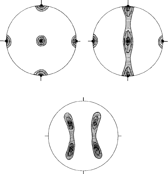
pole figure for the {100} planes will appear as shown in Fig. 12.14(a)—the {100} plane
normals cluster at the centre (i.e. normal to the sheet surface) and also along the rolling
and transverse directions giving contoured ‘peaks’ in these positions as shown. Now
suppose that the crystallites still remain aligned such that the
100
directions lie closely
parallel to the rolling direction but that the {100} planes are more randomly orientated
with respectto thesurfaceof thesheet. Thepole figurewill appear asin Fig. 12.14(b)—the
contour lines representing the distribution of the {100}plane normals are now spread out
towards the transverse directions. This pole figure corresponds closely to that for graphi-
tized carbon tapes (Fig. 10.13(b)) which shows the orientations of the graphite layers.
Pole figures may be prepared for any set of planes. For example the {111} pole figure
corresponding to the texture shown in Fig. 12.14(b) would consist of peaks of intensity as
1
A more detailed description of the use of stereographic projections in the analysis of orientation relation-
ships, with step-by-step examples, may be found in my article on Stereographic Techniques, Module 9.17 in
Procedures in Electron Microscopy (eds A. W. Robards and A. J. Wilson), John Wiley, 1993.
312 The stereographic projection and its uses
TD
TD
RD
(c)
RD RD
(a) (b)
TD
Fig. 12.14. (a)A {100}pole figure in which the {100}planes lie closely parallel to the sheet surface and
the
100
directions lie closely to the rolling direction (RD) and transverse direction (TD). The successive
levels of shading correspond to the contours of the orientations of plane normals and directions. (b) A
similar pole figure to (a) except that the {100} planes are more randomly distributed about the rolling
direction—the peaks are extended across the transverse direction. (c) A pole figure of the same texture
as (b) but now showing the orientations of the {111} planes.
shown in Fig. 12.14(c). Pole figures may be prepared in practice by a number of experi-
mental techniques—by the use of the texture goniometer as described in Section 10.4, by
recording backscattered electron diffraction patterns in the scanning electron microscope
(see Section 11.5.2) or by recording the orientation of individual grains in thin sections
in the light microscope. In general the textures observed are rather more complicated
than those of the simple examples described above and may consist of two or more
components, i.e. two or more sets of planes and directions may be aligned to a greater or
lesser extent parallel to the plane of the sheet and along the rolling direction respectively.
For example, Fig. 12.15(a) shows the {111} pole figure of heavily cold rolled copper in
which the texture may be described as (123)[41
¯
2] and (146)[21
¯
1] where the indices refer
to the planes orientated parallel to the rolling plane and the direction symbols refer to the
directions orientated along the rolling direction. Finally, Fig. 12.15(b) is a pole figure
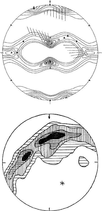
12.5 Applications of the stereographic projection 313
0.5
RD
c
N
Projection of
lineation
0.5
1
2
(a)
(b)
3
4
5
0.5
1
1
2
2
3
3
4
5
5
8
8
12
12
15
Fig. 12.15. (a) A {111} pole figure for heavily cold rolled copper, rolling direction RD vertical (from
H. Hu and S. R. Goodman, Trans. AIME, 227, 627, 1963). (b) A pole figure with contours shaded
as in Fig. 12.14, showing the orientations of the c-axes (or 0001 planes) of the quartz grains in a
metamorphosed psammite rock. These lie in a zone with a zone axis approximately parallel to the
lineation of the rock (from Introduction to Geology by H. H. Read and Janet Watson, Macmillan, 1968).
