Hammond C. The Basics of Crystallography and Diffraction
Подождите немного. Документ загружается.

264 X-ray diffraction of polycrystalline materials
(a) (b) (c) (d)
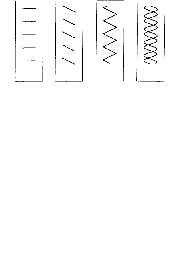
Fig. 10.15. Representational models of the DNA structure. (a) Lines spaced the helical repeat distance
p and length 0.6 p; (b) lines inclined at (approximately) the same angle as one of the arms of the helices;
(c) a zig-zag pattern made by combining the two arms of the helices and roughly representing the single
sine wave, in projection, of one of the helices; (d) two helices (represented as sine waves rather than
zig-zags) separated by a distance 3/8 p. (From A. A. Lucas et al. loc. cit.)
(a) (b) (c)
(d) (e)
Fig. 10.16. The optical transforms or diffraction patterns corresponding to the models shown in Fig
10.15(a)–(d) and Fig 10.14: (a) from horizontal lines spacing p and length 0.6p; (b) from lines inclined
as in one of the arms of the helices, the intensity maxima lie in a direction normal to the lines; (c) from
two sets of lines (zig-zags) representing the sine-wave projection of a single helix; (d) from two sine
waves separated by a distance 3/8 p; and (e) from the double-helix model as represented in Fig. 10.14.
(Photographs by courtesy of Prof. A. A. Lucas.)
10.5 X-ray diffraction of DNA: simulation by light diffraction 265
Next, we combine two zig-zags or two sine waves separated by the distance 3/8 p (Fig.
10.15(d)). The diffraction pattern is similar, but with the crucial difference that there are
gaps, or systematic absences, in the sequence of lines—the 4th (12th and 20th) lines
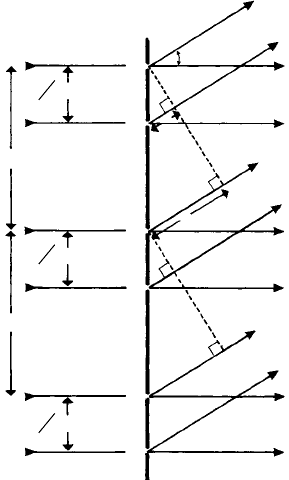
are missing (Fig. 10.16(d)). We can very easily understand this by drawing a diffraction
grating of slit separation p, working out the diffraction angles as in Section 7.4 and
then considering the contributions to the diffracted intensities of a second set of slits
separated by distance 3/8 p.Itisprecisely the same procedure that we used to determine
the diffracted amplitudes from a crystal with just two atoms per unit cell (Section 9.2
and Fig. 9.3(a)).
Figure 10.17(a) shows the geometry involved. Let f be the scattered amplitude from
each slit and consider first the interference between the diffracted beams from the slits
A– – –A– – –. Maxima occur when the path difference x = nλ = p sin α
n
≈ pα
n
and the
amplitude per unit length p (or per unit cell) is f . Now consider slits B– – –B– – –. We
only need consider the contribution of one such slit (i.e. in one cell), since what applies
to one applies to all. The path difference between each A and B slit, y = 3/8x = 3/8nλ
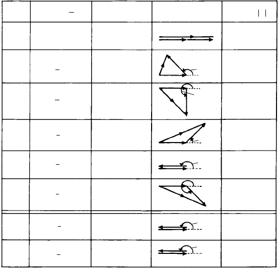
and we can now construct the amplitude- or vector-phase diagrams for n = 0, 1, 2, 3,
4 … The results, and corresponding intensities in terms of f
2
are shown in Fig. 10.17(b).
The cyclic variations in intensities with zeros at n = 4, 12, 20, etc. are clear.
Figure 10.16(e) shows the diffraction pattern of the double helix with the phosphate
groups and planar bases shown as in Fig. 10.14. Its similarity to well-defined X-ray
diffraction patterns of DNA is remarkable, especially so since it was arrived at by such
simple procedures.
α
n
3
(a)
8
p
p
p
A
B
y
x
A
B
A
B
3
8
p
3
8
p
Fig. 10.17. (continued)
266 X-ray diffraction of polycrystalline materials
n
Path diff,
n
Phase angle
F
Intensity,
F
2
0
(b)
1
2
3
4
5
12
20
0
135°
270°
405° (45 )°
540° (180 )°
675° (315 )°
1620° (180 )°
2700° (180 )°
f
f
f
f
f
F
F
135°
270°
f
f
f
F
45°
f
f
180°
f
F
f
f
f
180°
f
f
180°
4
f
2
0.586
f
2
2
f
2
3.414
f
2
0
3.414
f
2
0
0
Amplitude,
F
0
8
3
λ
λ
3
8
1
λ
1
8
λ
3
4
1
λ
1
2
1
λ
7
8
3
λ
1
2
7
λ
1
2
Fig. 10.17. (a) A diffraction grating of repeat distance p made up of two sets of slits A…A and
B…B…separated by distance 3/8 p. Maxima occur when the path difference x = nλ = p sin α
n
.
The amplitudes or intensities of the diffracted beams are modulated by interference between the waves
diffracted at each pair of slits A and B. (b) The vector-phase diagram for values of n = 0, 1, 2, 3, 4,
indicating zero intensity for n = 4 (and 12, 20, etc.).
However, there is a further problem to be solved. It was known (prior to 1952) that the
sugar-phosphate groups of nucleic acids were polar; the sequence of phosphate groups
along one direction is reversed in the opposite direction—in an analogous way as the
sequence of Zn and S atoms along a 111 (polar) direction in zincblende (Section 4.7).
How, therefore, are the two helices (Fig. 10.14) related; do the DNA backbones run
in the same, or in opposite directions? Francis Crick showed that they in fact ran in
opposite directions. The story is as follows
3
. As mentioned above, within living cells
the DNA is surrounded by the high water content of the cell as in a B-DNA fibre.
3
Again, I am indebted to Professor Amand Lucas on whose paper, A-DNA and B-DNA: Comparing their
Historical X-ray Fibre Diffraction Images, Journal of Chemical Education 85, 737 (2008) I have largely based
this brief account. Professor Lucas and his colleagues have also prepared (available on request) two slides;
one consisting of nine optical masks for B-DNA and the other twelve optical masks consisting of the same
nine masks for B-DNAplus two additional masks for A-DNA and one mask to disprove the co-oriented model
of double-stranded DNA. The use of these masks, in demonstrating the relations between the structures and
diffraction patterns of DNA, is explained in the paper.
10.6 The Rietveld method for structure refinement 267
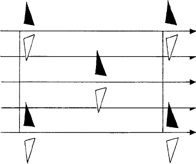
Fig. 10.18. A portion of a pattern based on space group C2. An (open) triangle at height + is turned
over by the operation of a horizontal diad axis (double-headed arrows along the y-axis) to one at height—
(black triangle). The pair of triangles is repeated by the C-face-centring lattice point. Screw diad axes
(single-headed arrows) arise between the diad axes.
However, when the water content of the fibre is reduced, the strands shrink slightly,
but more importantly, they pack together in nearly, but not quite, an hexagonal array
(A-DNA). In order to achieve the most efficient packing, the helical ‘grooves’ of one
strand locate into the ‘projections’ of the next—in just the same way that a bundle of
ordinary screws (or threaded rods) pack together; the ‘tops’ of the threads of one screw
fitting in to the ‘bottoms’ of the threads of the next. This results (in the case of A-DNA)
in a C-face centred monoclinic, rather than an hexagonal unit cell. Gosling and Franklin
determined the space group to be C2 (a ‘permissible’ space group—see Table 4.1): the
only symmetry elements which the unit cell possesses are the diad (and screw diad) axes
running perpendicular to the strands. Crick realized that, since the cell possessed diad
symmetry, the DNA molecules must also possess diad symmetry and that the only way
this could be achieved was for the polar backbones to run in opposite directions. This
is readily seen in Fig. 10.18, the black and white triangles, related by diad symmetry,
representing the opposite, or counter-oriented molecular chains. This deduction, arrived
at by such simple crystallographic reasoning, was of crucial importance in guiding
Watson and Crick in their model building of the structure of DNA.
10.6 The Rietveld method for structure refinement
Powder diffraction data has long been used to identify and characterize crystalline mate-
rials, particularly through the use and development of the X-ray Powder Diffraction
File (Section 10.3.2). However, until the advent of the Rietveld method it was little
used for the determination of all but the simplest of crystal structures largely on account
of overlapping peaks and the consequent difficulty of accurately measuring integrated
268 X-ray diffraction of polycrystalline materials
intensities, this being the first step in determining the structure factors of the reflections
which can be then used, as in single-crystal data, to solve or refine structures. This peak
profile fitting procedure clearly only works for relatively simple structures which yield
diffraction patterns with minimal peak overlap. One may say that the first such peak
profile-fitting procedure was carried out (albeit with single crystals) by W. L. Bragg in
1913 who established, from relative peak intensities, the location of the S atoms in FeS
2
(Section 4.7, Fig. 4.16).
The Rietveldmethod, incontrast, doesnotmeasure, norattempt to measure, integrated
intensities as such but records the whole powder diffraction pattern: the measurement
of intensity at each 2θ step constitutes a data point and the whole set of such data
points is compared with those calculated. The calculation takes into account not only
structural parameters (unit cell size, atom positions and occupancy factors) but also
scale factors, background intensity coefficients and profile parameters describing peak
shapes and widths. These parameters are then varied in a least-squares procedure until
the calculated pattern best matches the observed pattern. The quantity R to be minimized
is given by:
R =
i
w
i
(
Y
io
− Y
ic
)
2
where Y
io
is the observed intensity at step i, Y
ic
is the calculated intensity and w
i
is a
weighting assigned to each step—the stronger the observed intensity (i.e. the smaller the
counting error), the larger is w
i
.
Such is the process of Rietveld refinement, but in order for it to be successful a
large number of conditions, both theoretical and experimental, need to be met. First
the ‘input’ structure (unit cell dimensions, atom positions, occupancy of atomic sites,
etc.) needs to be a close approximation of that which is ultimately to be determined
by the refinement—how close depends of course on the complexity of the structure.
Then, as mentioned above, account must be taken of all the other factors which affect
the observed intensities: fluorescence from the specimen, detector noise, thermal diffuse
and incoherent scattering, scattering from the sample holder, beam collimator and slits
and preferred orientation (Section 10.4). The Rietveld method is able to accommodate
moderate amounts of preferred orientation, which may otherwise be difficult or impossi-
ble to eliminate (see point 3 below), by the inclusion of refining parameters which model
the effect. In so doing preferred orientation may both be quantified and also removed as
a confounding influence on the other variables.
The experimental conditions are no less demanding. They may be summarized as
follows:
(1) Accurate alignment of diffractometer (to ensure accurate 2θ values).
(2) Correct positioning of specimen (both in the diffractometer and Debye–Scherrer
arrangement).
(3) Correct choice of Soller slits (which limit lateral beam divergence in the diffrac-
tometer) to avoid low-angle peak ‘tails’ in low-2θ reflections.
10.6 The Rietveld method for structure refinement 269
(4) Elimination (as far as possible) of preferred orientation effects; even the process of
pressing a powder into a holder, or introducing it into a capillary tube, can give rise
to preferred orientation.
(5) Constant volume condition. In the Debye–Scherrer arrangement this is achieved
automatically (except in the case of strongly-absorbing specimens). In the diffrac-
tometer it is achieved if the incident beam remains within the area of the specimen
(a potential problem at low 2θ angles) and if the beam does not penetrate to the
underlying holder (i.e. is regarded as ‘infinitely thick’). The constant volume con-
dition arises because the area of specimen irradiated varies as 1/ sin θ and the depth
of operation varies as sin θ, hence the volume is independent of θ. Some diffrac-
tometers incorporate divergence slits which open out as 2θ increases—resulting in
a gain in intensity, and hence reduced counting errors, at high 2θ angles but also an
increase in irradiated volume which must be accounted for.
(6) Apowder particle size of ∼1–5 μm; for sizes smaller than this line broadening needs
to be taken into account and for sizes much larger than all crystallite orientations
may not contribute equally to the intensity, a problem akin to preferred orientation.
All these considerations indicate the complexity of the computer programs required
in a Rietveld refinement.
The technique was invented, and the first programs written, by Hugo M. Rietveld
to refine structures recorded by neutron, rather than X-ray, diffraction. He records that
when he first announced the techniques at the Seventh Congress of the IUCr in Moscow
in 1966, ‘the response was slight, or rather non existent’.
4
Since then it has become a
major tool in structure determination, particularly since increasing computer power has
led to its application in X-ray diffraction (where line profiles are more complex than those
in neutron diffraction). Apart from being able to solve the structures of intrinsically-fine
crystalline materials it has found particular application in, e.g., perovskites and super-
conductors in which the various structural forms arise from displacive transformations
(see Section 1.11). It is also able to deal with multiphase specimens and to detect the
presence of amorphous components.
The final word must come from Rietveld himself ‘… the method is not to be treated as
a black box. One must be continually aware of the limitations, not only of this method,
but in general of all least squares methods.’
4
Exercises
10.1 Show, by simple geometrical reasoning, that in the X-ray monochromator (Fig. 10.2) the
curved reflecting crystal planes should have a radius twice that of the focusing circle.
10.2 Show, by simple geometrical reasoning, that in the back-reflection X-ray powder photo-
graph (Fig. 10.5), the reflections are most sharply focused when R
2
= xy where R = the
radius of the ring, x = the specimen–film distance and y = the distance of the (effective)
source S behind the film.
4
H.M. Rietveld, ‘The early days, a retrospective view,’ in The Rietveld Method p. 39–42, ed. R.A. Young.
IUCr/Oxford Science Publications, Oxford University Press, Oxford (1993).
270 X-ray diffraction of polycrystalline materials
10.3 Determine the d-spacings of the strongest low-angle reflections in the Debye–Scherrer film
of quartz (Fig. 10.7) and check that they correspond (within the limits of experimental
accuracy) with those indicated in Fig. 10.4 or listed in Fig. 10.8.
(Hint: the precise locations at which 2θ = 0 and 180
◦
are not found from the centres of
the holes in the film (which might be slightly displaced) but by determining the mid-points
of the low-angle and high-angle reflections, respectively. The distance between these mid-
points corresponds to an angle of 180
◦
and the linear scale can be related to the angular
scale and the 2θ values. Hence the d-spacings of the reflections can be found using Bragg’s
law. (The film is taken using filtered CuKα radiation which includes both the Kα
1
and Kα
2
components. At low angles these are unresolved, λCuK ¯α = 1.542 Å, but at high angles
they are resolved, λCuKα
1
= 1.541 Å, λCuKα
2
= 1.544 Å.)
10.4 Crystalline polypropene may be assigned a monoclinic unit cell with lattice parameters
a = 6.65 Å, b = 20.96 Å, c = 6.50 Å and β = 99.3
◦
(see Section 4.8.2). The polymer
chains are orientated along the c-axis. The table shows the d spacings, relative intensities
and corresponding hk0, hkl and hk2 indices (data from Natta, G., Corradini, P. and Cesari,
M. (1956), Rend. Acad. Naz. Lincei 21, 365).
d/Å(hk0) Intensity
†
d/Å(hk1) Intensity
†
d/Å(hk2) Intensity
†
6.21 110 s 4.14 111 m 3.06 022 mf
5.20 040 vs 4.06 131 s 3.05 112 mf
4.74 130 s 4.03 041 s 2.50 202 f
3.50 150 m 2.11 202 mf
3.46 060 m
3.25 200 mf
3.11 220 mf
†
Intensities: s = strong, v = very, m = medium, f = faint.
2degrees
44.0 44.5 45.0 45.5 46.0 64.0 64.5 65.0 65.5 66.0 81.5 82.0 82.5 83.0 83.5 84.0
44.0 44.5 45.0 45.5 46.0 64.0 64.5 65.0 65.5 66.0 81.5 82.0 82.5 83.0 83.5 84.0
Intensity (arbitrary units)
(a)
(b)
θ
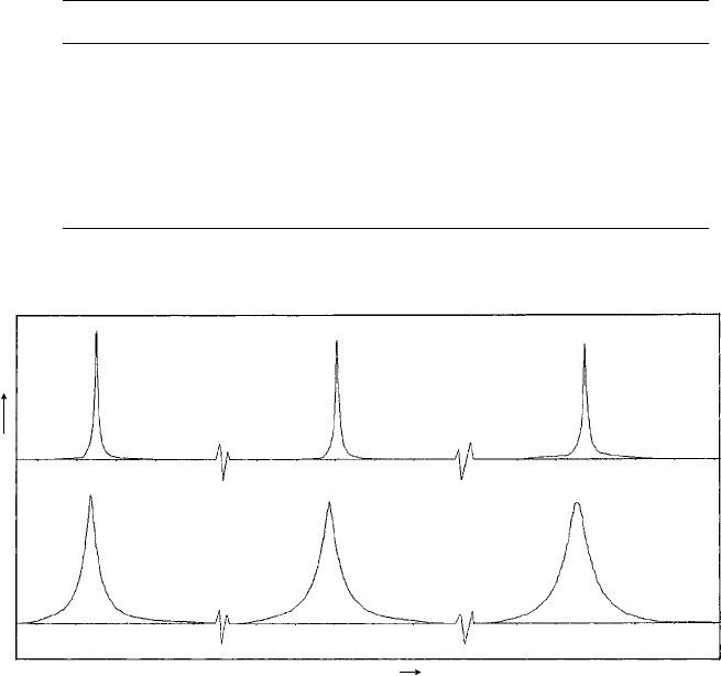
Fig. 10.19. Diffractometer charts (CuKα
1
radiation, λ = 1.541 Å) showing the first three reflections
for a steel specimen (α-Fe, bcc) in (a) the annealed condition and (b) after heavy surface abrasion giving
broadened and shifted X-ray diffraction peaks which arise from residual stresses on the micro- and
macroscale and a reduction in crystallite size. (Data by courtesy of Mr D. G. Wright.)
Exercises 271
Given that the X-ray photographs in Fig. 10.11 were taken with CuKα radiation (λ =
1.542 Å) and that the specimen-film distance (corrected for printing = 36 mm), index the
reflections and show that in Fig. 10.11(b) the polymer chains are orientated along the
tensile axis.
10.5 With reference to Fig. 10.19, determine β (expressed in radians) for each of the peaks from
the half-height peak widths of the annealed (β
Inst
) and abraded (β
OBS
) specimens. On
rtibra(ytisnetnI)stinuyra
(1010)
(1011)
(0002)
6.00
×10
1
6.00
5.40
5.80
4.20
3.60
3.00
2.40
1.80
1.20
0.60
34.0 36.0 38.0 40.0 42.0 44.0
×10
2
5.40
4.80
4.20
3.60
3.00
2.40
1.80
1.20
0.60
34.0 36.0 38.0 40.0 42.0 44.0
(a)
rtibra(ytisnetnI)stinuyra
(1010)
(1011)
(0002)
(110)
(b)
α
α
α
degrees 2
θ
degrees 2
θ
α
α
α
β
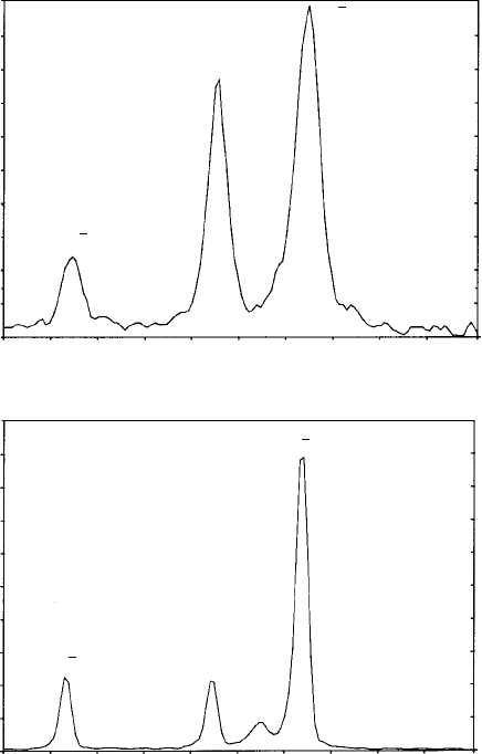
Fig. 10.20. Diffractometer charts (CuKα
1
radiation, λ = 1.541 Å) showing the first three reflections
for a titanium alloy (Ti-6% Al-4% V) powder specimen in (a) the mechanically milled condition and (b)
following consolidation and heat treatment which gives rise to an increase in grain size and precipitation
of the β phase (bcc) in the α phase (hexagonal) alloy matrix. (Data by courtesy of Mr D. G. Wright and
Dr A. Brown.)
272 X-ray diffraction of polycrystalline materials
the assumption that the broadening arises solely from microstrain, determine the micros-
train and hence residual stress given the Young modulus for iron E = 207 GPa (see
Section 10.3.4).
10.6 With reference to Fig. 10.20, electron microscopy indicates that the grain size of the milled
powder (a) is in the range 10–50 nm and that of the consolidated powder (b) is 5 μm and
above. On the basis that the increased broadening in (a) arises solely as a result of the fine
crystallite size, show that the X-ray data is consistent with the microscopical data.

11
Electron diffraction and its
applications
11.1 Introduction
In Section 7.3 we discussed the wave- and particle-like characters of light which are
linked by Planck’s equation E = hc/λ; and also the wave-like character of moving
particles which is linked to their mass and velocity by de Broglie’s equation λ = h/mv.
The common or ‘linking factor’ in both equations being Planck’s constant h = 6.63 ×
10
−34
Js. In the caseof neutrons (Section9.7 and Exercise9.3), itisthe thermalconditions
in the reactor which give rise to the neutron velocities, and hence mv values which, when
substituted in de Broglie’s equation, give wavelengths very similar to those for X-rays
(Section 9.7). In the case of electrons in the transmission electron microscope the velocity
and hence momentum mv of the electrons (m being relativistically corrected) depends on
the accelerating voltage V and is determined by equating the potential energy eV (lost)
where e is the charge on the electron with the kinetic energy
1
2
mv
2
(gained). The resulting
λ values are very small (see Exercise 11.l), for example in a microscope operating at
300 kV, λ = 1.97 pm (0.0197 Å) and this of course is the basis of the high resolving
power (or small limit of resolution) of the electron microscope in comparison with
the light microscope as described in Section 7.5. Finally, it should be emphasized that
de Broglie’s equation applies to all moving particles, not just neutrons and electrons—
including pieces of chalk thrown at inattentive students in lectures! However, as a simple
calculation shows, the associated wavelengths are very small.
Whereas X-rays are scattered by the electrons in atoms, the incident electrons are
primarily scattered by the protons in the nuclei, the scattering amplitude being propor-
tional to Z. The electrons do, however, play a role insofar as they ‘shield’ the nuclei
from the incident electrons by an amount proportional to f , the X-ray atomic scattering
factor. Hence, the electron atomic scattering amplitude, f
e
is proportional to (Z −f ). It is
normally expressed as a scattering length (rather than a number like f ) and the electron
scattering intensities are thus expressed as areas or atomic scattering cross-sections.
The important consequence is that on average f
e
∝
3
√
Z (rather than f ∝ Z for
X-rays) so that light elements scatter more strongly, in comparison to heavy elements,
than X-rays. More important still the amount of scattering is much greater than for X-rays
by a factor of l0
3
or l0
4
such that electron beams are attenuated much more rapidly. Hence
in electron diffraction the dynamical interactions discussed in Section 9.l are much more
important than in X-ray diffraction and must always be taken into account in any attempt
to relate observed electron beam intensities to atomic positions. There is, in electron
