Gottstein G., Shvindlerman L.S. Grain Boundary Migration in Metals: Thermodynamics, Kinetics, Applications
Подождите немного. Документ загружается.

516 6 Applications
(a) (b)
(c)
[hkl]
010
TD’
TD
RD
001
100
ND
ND
001
010
100
RD”
RD’
RD
φ
TD
ϑ
ω
[uvw]
ϕ
1
ϕ
2
ϕ
2
φ
ϕ
1
ϕ
1
ϕ
2
φ
ϕ
1
ϕ
1
RD
ND
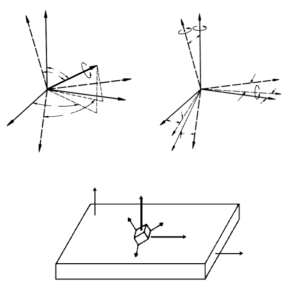
FIGURE 6.4
Different representation of an orientation relationship: (a) axis and angle of
rotation; (b) Euler angles; (c) Miller indices.
© 2010 by Taylor and Francis Group, LLC

6.1 Characterization of Microstructure and Texture 517
(i =1, 24). S
c
i
is any of the 24 cubic symmetry matrices. In addition there may
be a specimen symmetry, like the orthorhombic specimen symmetry of a rolled
specimen. If the specimen symmetry matrices are denoted by S
s
k
(k =1,max),
then
r
ik
=
S
c
i
g · (S
s
k
)
−1
r (6.12)
6.1.3.2 The Rotation Matrix
Except for the symmetry relations given in Eq. (6.11) the rotation matrix is
unique, irrespective of the way it is derived. It can be expressed in terms of
Euler angles, Miller indices and axis-angle pair as given below. A calculation
of the rotation matrix is given in Appendix B.
g in terms of Euler angles g{(ϕ
1
, Φ,ϕ
2
)} is defined as
g=
2
6
6
4
cos ϕ
1
cos ϕ
2
−sin ϕ
1
sin ϕ
2
cos φ sin ϕ
1
cos ϕ
2
+cos ϕ
1
sin ϕ
2
cos φ sin ϕ
2
sin φ
−cos ϕ
1
sin ϕ
2
−sin ϕ
1
cos ϕ
2
cos φ −sin ϕ
1
sin ϕ
2
+cos ϕ
1
cos ϕ
2
cos φ cos ϕ
2
sin φ
sin ϕ
1
sin φ −cos ϕ
1
sin φ cos φ
3
7
7
5
(6.13)
g in terms of Miller indices g{(hkl)[uvw]} is defined as
g =
⎡
⎣
u
N
1
v1−kw
N
3
h
N
2
v
N
1
hw−u1
N
3
k
N
2
w
N
1
uk−vh
N
3
l
N
2
⎤
⎦
(6.14)
where N
1
=
√
u
2
+ v
2
+ w
2
, N
2
=
√
h
2
+ k
2
+ l
2
,andN
3
= N
1
· N
2
;
g in terms of axis and angle of rotation g{ω[a
1
,a
2
,a
3
]} is defined as
g=
2
6
6
4
(
1−a
2
1
)
cos ω+a
2
1
a
1
a
2
(1−cos ω)+a
3
sin ωa
1
a
3
(1−cos ω)−a
2
sin ω
a
1
a
2
(1−cos ω)−a
3
sin ω
(
1−a
2
2
)
cos ω+a
2
2
a
2
a
3
(1−cos ω)+a
1
sin ω
a
1
a
3
(1−cos ω)+a
2
sin ωa
2
a
3
(1−cos ω)−a
1
sin ω
(
1−a
2
3
)
cos ω+a
2
3
3
7
7
5
(6.15)
Since the rotation matrix is unique and independent of its derivation, Euler
angles, Miller indices and axis and angle of rotation can be extracted from a
given rotation matrix with the relations given above.
6.1.3.3 Stereographic Projection, Pole Figure and Inverse Pole
Figure
Orientations are most commonly represented by their pole figures in the
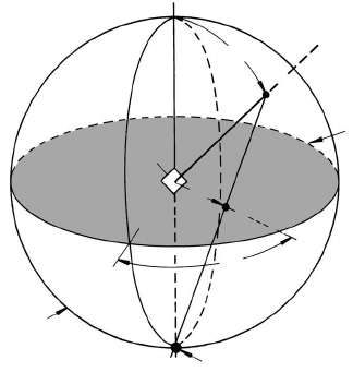
stereographic projection (Fig. 6.5). The stereographic projection is a two-
dimensional image of the three-dimensional orientation space. It is constructed
by placing the origin of the coordinate system in the center of a sphere. A
direction [hkl] (or the normal of a plane (hkl)) centered in the origin will
intersect a surrounding sphere at a point P . The connection of P with the
south pole S of the sphere intersects the equatorial plane at P
. P
is called
the pole of the direction [hkl] (or plane (hkl)). The projection of different low
© 2010 by Taylor and Francis Group, LLC
518 6 Applications
reference sphere
center of projection S
equatorial plane =
projection plane
α
α
β
P
P'
E
FIGURE 6.5
Illustration of the principle of stereographic projection: E — crystallographic
plane, P
—poleofE in stereographic projection.
index directions with [001] pointing to the north pole of the sphere — which
becomes the center of the projection — is called the (001) or standard pro-
jection.
Limitation to only one set of crystallographically equivalent poles {hkl}
represents the {hkl} pole figure in standard projection (Fig. 6.6). All other
poles can be constructed by means of the known crystal symmetry. For the
standard projection pole figures are trivial and superfluous. The reference co-
ordinate system, however, is usually the specimen coordinate system {S}.The
orientation of a crystallite with respect to {S} is then denoted by the posi-
tion of its poles within this reference system. This may be illustrated by an
example.
A rolled sample has the distinguished specimen coordinate axes: rolling di-
rection (RD) and rolling plane normal (ND). Consequently, the third orthogo-
nal axis is the transverse direction (TD). The {hkl} pole figure of a crystallite
is then given by the position of the poles {hkl} within this coordinate system.
The orientation relationship between specimen coordinate system and crys-
tal coordinate system is usually and easily described by the crystallographic
direction parallel to the rolling plane normal (hkl) and the rolling direction
[uvw].
While in normal pole figures the crystal orientation is represented with
respect to a given specimen coordinate system as a reference, in the inverse
pole figure the specimen coordinate system is represented with respect to a
given crystal coordinate system (standard position) as a reference (Fig. 6.7).
This is most useful if only one specimen axis is distinguished, like the axis of a
© 2010 by Taylor and Francis Group, LLC
6.1 Characterization of Microstructure and Texture 519
(a) (b)
(c)
ND ND
RD
RD
1
2
3
1' 1'
2'
2'
3'
3'
100
100
010
010
001
001
β
1
α
1
(a) (b)
(c)
ND ND
RD
RD
1
2
3
1' 1'
2'
2'
3'
3'
100
100
010
010
001
001
β
1
β
1
α
1
α
1
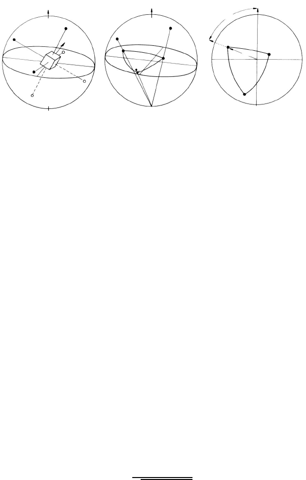
FIGURE 6.6
Representation of an orientation in terms of the {100} axes in stereographic
projection. (a) Position of the crystal at the center of the orientation sphere;
(b) stereographic projection of the cubic axes; (c) {100} pole figure showing
orientation and definition of the angles α
1
and β
1
associated with pole 1.
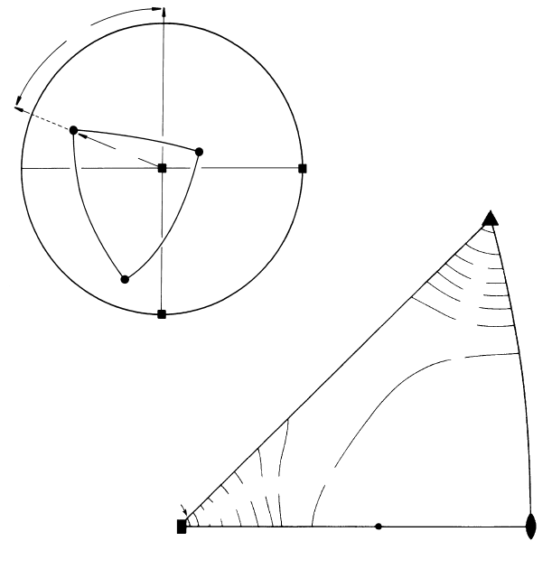
wire or a tensile specimen. In cubic crystals the representation can be reduced
to only one characteristic stereographic triangle framed by, e.g. (001)–(011)–
(
¯
111), because of the crystal symmetry.
For more difficult specimen geometries the inverse pole figure can also be
constructed, but it is less convenient to use, since the whole projection plane
is needed to represent more than one axis in an inverse pole figure. Therefore,
in such cases, a representation as a pole figure is more appropriate and easier
to imagine.
6.1.3.4 Measurement and Analysis of Pole Figures
The importance of pole figures can be attributed to the fact that they can be
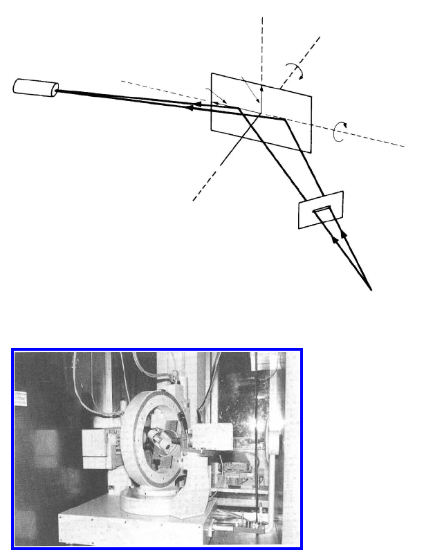
experimentally determined with an X-ray texture goniometer. Its principle of
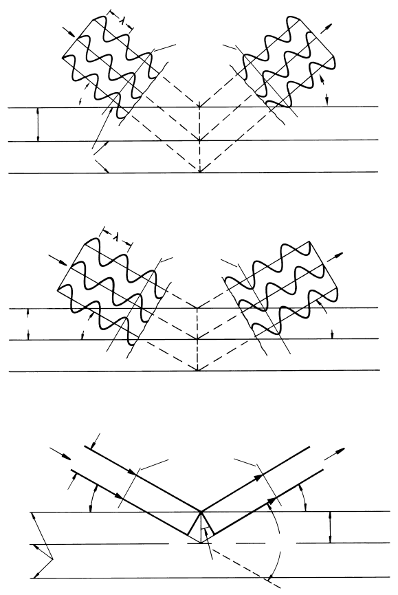
operation is based on Bragg’s law, i.e. the reflection of X-rays of wavelength
λ is obtained from a set of planes {hkl} if
λ =2d · sin Θ (6.16)
where Θ is the angle between incident X-ray beam and lattice plane normal
{hkl} (Fig. 6.8). The spacing d between adjacent planes {hkl} in cubic crystals
is given by
d =
b
√
h
2
+ k
2
+ l
2
(6.17)
where b denotes the lattice parameter.
The lattice plane normal {hkl} bisects the incident and reflected beam at
an angle Θ. For a given wave length λ and for a constant angle 2Θ between
© 2010 by Taylor and Francis Group, LLC
520 6 Applications
(001)
(012) (011)
0
(b)
5
(111)
2.5
10
5
25
1
1
0.5
1
15
0.5
20
22.5
0
20
15
10
2.5
α
1
β
1
RD
TD
ND
001
010
100
1'
2'
3'
(a)
FIGURE 6.7
(a) Diagramatic illustration of the inverse pole figure of a sample of rolled ma-
terial; (b) Inverse pole figure of extruded aluminum wire (sample orientation
= wire axis). The lines indicate contours of equal measured intensity (after
[569]).
© 2010 by Taylor and Francis Group, LLC

6.1 Characterization of Microstructure and Texture 521
X-ray source and counter a reflected signal is counted only if a plane {hkl}
is in reflection position. By rotating the specimen around two perpendicular
specimenaxesuptoideally90
◦
all possible positions of planes {hkl} will be
found. Since Bragg’s law does not discriminate signs of {hkl} all combina-
tions of {±h, ±k, ±l} will contribute, i.e. all equivalent poles will be recorded
(Fig. 6.9).
If the specimen is a polycrystal, all crystallites having a set {hkl} in re-
flection position will contribute to the measured intensity for a given position
(α, β) of the specimen. The result of such a measurement is the frequency
of occurrence of a given pole {hkl} in all illuminated crystals for any given
position (α, β) of the specimen, i.e. the pole intensity distribution.
To keep evaluation simple, low index poles like {200}, {220} and {111} for
fcc crystals are usually chosen
3
.
The pole figure represents the distribution of a specific family of lattice
planes in the stereographic projection. Because of the known crystallography
of the reflecting crystal lattice, it is possible to determine the orientation of an
illuminated crystal. To begin with, all poles which belong to the same orienta-
tion, for instance, all four {111} or all three {100} poles have to be identified.
Since the angles between these crystallographic directions (for instance 90
◦
between any two {100} poles) are known, the orientation can be calculated.
A worked example is given in Appendix C.
In case of single crystals or very simple types of textures (for instance, the
Cube texture) the evaluation of a single pole figure is sufficient to determine
the orientation, since the poles belonging to the same orientation are easy to
identify. However, if several orientations occur concurrently, it is possible that
poles of different orientations overlap, which renders impossible an unambigu-
ous association of poles to a defined orientation. In such a case it is necessary
to utilize more than one pole figure to identify orientations. In experimental
pole figures of polycrystals, however, an identification of all components is
extremely difficult even when several pole figures are known. In particular,
a quantitative analysis of weaker components is practically impossible. The
fundamental reason for this deficiency of a texture analysis by means of pole
figures is the fact that a pole figure is a two-dimensional projection (of the
crystal axes) of a three-dimensional quantity (the orientation). This projection
is accompanied by a loss of information, which would be necessary to identify
the poles belonging to a common crystal orientation. However, in the past 20
years mathematical tools have been developed that use high-power computers
to calculate the orientation distribution function (ODF) from a few measured
pole figures [567]. The result of this computation is not unambiguous. In fact,
it is impossible to determine the true ODF from experimental pole figures.
This is due to the fact that Bragg’s law does not differentiate between {hkl}
3
Because of extinction, in fcc crystals only reflection occurs where the Miller indices are
either all even or all odd, i.e. {111}, {200}, .... In bcc crystals, reflections only occur if the
sum h + k + l is even, i.e. {110}, {200}, ....
© 2010 by Taylor and Francis Group, LLC
522 6 Applications
wave front
wave front
wave front
(a)
incident
X-rays
incident
X-rays
incident
X-rays
(b)
(c)
no reflected
X-radiation
d
(hkl) planes
Θ
Θ
reflected
X-radiation
reflected
X-radiation
Θ
Θ
Θ
Θ
2
Θ
Θ
d
d
ray 1
ray 2
M
N
O
P
(hkl) planes
FIGURE 6.8
X-ray diffraction by a crystal lattice can be regarded as reflection from a semi-
reflecting mirror. Only if rays diffracted by parallel planes are in phase (b)
(equal phase in every plane perpendicular to the direction of propagation),
they will not cancel each other out (like in (a)) and reflection will occur. Equal
phase will result only if the path difference from successive planes (MPN in
(c)) is an integral number of wave lengths. This condition leads to the Bragg
equation.
© 2010 by Taylor and Francis Group, LLC
6.1 Characterization of Microstructure and Texture 523
β
(b)
diffractiometer
axis
counting tube
source
A
B'
A'
TD
RD
B
C
ND
D
α
β
(a)
β
(b)
diffractiometer
axis
counting tube
source
A
B'
A'
TD
RD
B
C
ND
D
α
β
(a)
β
(b)
diffractiometer
axis
counting tube
source
A
B'
A'
TD
RD
B
C
ND
D
α
β
(a)
FIGURE 6.9
(a) Beam geometry and sample rotation in an X-ray-texture goniometer (here:
the Schulz reflection method); (b) X-ray-texture goniometer at the IMM.
© 2010 by Taylor and Francis Group, LLC

524 6 Applications
and {
hkl} poles so that from pole figures only the symmetrical components
of the ODF can be determined. There are also a variety of methods to deter-
mine the asymmetrical components; however, such solutions are not unique.
Usually the omission of the odd coefficients generates so-called ghosts, that
is, falsely pretended intensities in the ODF, which can be corrected for, if
the major components of the ODF are known. If, however, the true ODF of
an unknown texture ought to be determined, it would be more reasonable to
complement macroscopic pole figure measurements by single grain orientation
measurements in terms of orientation imaging microscopy (OIM), from which
the true ODF can be calculated, although the number of measured individ-
ual grains may be much smaller than the number of grains contributing to
the intensity in the X-ray pole figure measurements [570, 571]. It has been
demonstrated recently that, for reasonably defined textures, the true ODF
of a polycrystalline specimen can be calculated with sufficient accuracy from
about a thousand randomly sampled individual grain orientation measure-
ments.
6.1.3.5 The Orientation Distribution Function (ODF)
The association of poles belonging to a particular orientation from the in-
tensity distribution in a pole figure of a polycrystal is usually impossible to
determine. The problem can be alleviated by measuring a second pole figure
and identifying orientations which comply with both pole figures. This is very
tedious but it often helps remove ambiguity or rule out the occurrence of a
particular orientation.
A famous example for illustration of this problem is the cube orientation
in the Cu-rolling texture. As will be shown below, a sharp cube texture is
the recrystallization texture of the Cu-type rolling texture. For elucidation
of the texture development it is most important to know whether the cube
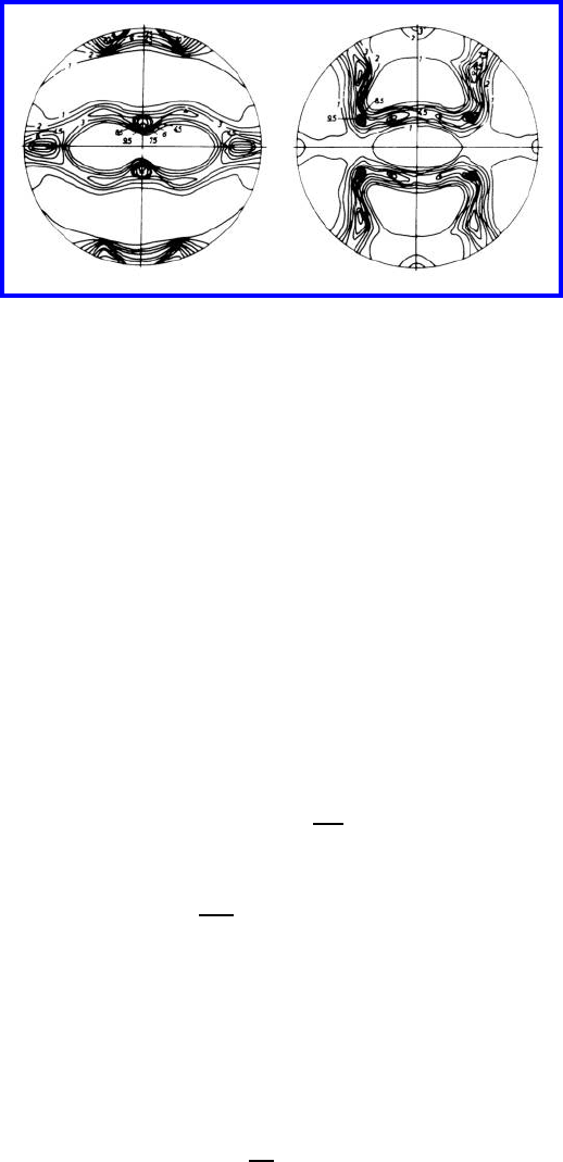
orientation is already present in the rolling texture. The {111} pole figure of
the rolling texture indicates (falsely) that this might be the case (Fig. 6.10).
But the {200} pole figure of the rolling texture reveals a definite absence of
the cube orientation (001)[100] in the deformed material, as evident from the
missing intensity in the center of the {200} pole figure.
In most cases even two pole figures are not sufficient for obtaining an
unambiguous assignment, leaving alone the cumbersome task to compare
the possible orientations. Modern texture analysis instead utilizes the three-
dimensional orientation space. This is the space where any orientation is rep-
resented unambiguously by only one point. Orientation space is set up by
the axes of a three-dimensional coordinate system, where each axis represents
one of the three quantities that define a given rotation. Correspondingly, the
origin (i.e. no rotation) is the standard orientation (or the orientation of any
given external reference system).
Most common is the rectangular coordinate system with the three Euler
© 2010 by Taylor and Francis Group, LLC
6.1 Characterization of Microstructure and Texture 525
Cu 99.99 {111} Cu 99.99 {200}Cu 99.99 {111} Cu 99.99 {200}
FIGURE 6.10
{111} and {200} pole figures of 95% rolled Cu.
angles ϕ
1
, Φ,ϕ
2
as axes. Any point g
0
ϕ
0
1
, Φ
0
,ϕ
0
2
in orientation space is
uniquely described by its Euler angles and, therefore, represents exactly the
orientation which is obtained by rotating the standard position (0, 0, 0) by
the angles ϕ
0
1
, Φ
0
,ϕ
0
2
. This three-dimensional orientation space is also referred
to as Euler space.
For cubic crystal symmetry and orthorhombic specimen symmetry (like in
rolling) all orientations occur three times in the triple unit cell 0 ≤ ϕ
1
, Φ.ϕ
2
≤
π/2 [568]. The function f(g) which describes the frequency of occurrence (in-
tensity) of any particular orientation g in a crystalline aggregate is called the
three-dimensional orientation distribution function (ODF). As pointed out in
Section 5.1.3.1 the value of f(g)foragiveng represents the volume frac-
tion dV/V of material that has an orientation within an infinitesimal volume
around g in orientation space
f(g)dg =
dV
V
(6.18)
which takes note of the normalization
1
8π
2
f(g)dg = 1 (6.19)
where integration is performed over a complete unit cell of the orientation
space.
The measured {hkl} pole figure P
hkl
gives only the distribution of a par-
ticular crystal axis [hkl]. Every orientation that has an axis [hkl] at a given
point P
0
in the pole figure contributes to the intensity at P
0
. With a point in
the {hkl} pole figure given by its polar coordinates (α, β) the intensity P
hkl
is given
P
hkl
(α, β)=
1
2π
2π
0
f(α, β, γ)dγ (6.20)
© 2010 by Taylor and Francis Group, LLC
