Gibilisco S. Teach Yourself Electricity and Electronics
Подождите немного. Документ загружается.

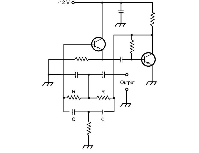
The Twin T Oscillator
An audio oscillator circuit that is popular for general-purpose use is the twin T oscillator (Fig. 24-18).
The frequency is determined by the values of the resistors R and capacitors C. The output is a near-
perfect sine wave. The small amount of distortion helps to alleviate the irritation produced by an ab-
solutely pure sinusoid. The circuit shown in this example uses two PNP bipolar transistors. They are
biased for class A amplification.
The Multivibrator
Another popular AF oscillator circuit makes use of two identical common emitter or common
source amplifier circuits, hooked up so that the signal goes around and around between them. This
is sometimes called a multivibrator circuit, although that is technically a misnomer, the term being
more appropriate to various digital signal-generating circuits.
In the example of Fig. 24-19, two N-channel JFETs are connected to form a multivibrator for
use at AF. Each stage amplifies the signal in class A, and reverses the phase by 180°. Therefore, the
signal goes through a 360° phase shift each time it gets back to any particular point. A 360° phase
shift is equivalent to no phase shift at all, so it results in positive feedback.
Audio Oscillators 401
24-18 A twin T audio oscillator using two PNP bipolar
transistors. The frequency is determined by the
values of the resistors R and the capacitors C.
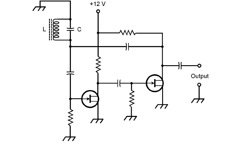
The frequency of the circuit shown in Fig. 24-19 is set by means of an LC circuit. The coil uses a
ferromagnetic core, because stability is not of great concern and because such a core is necessary to ob-
tain the large inductance needed for resonance at AF. Toroidal cores or pot cores are excellent in this
application. The value of L can range from about 10 mH to as much as 1 H. The capacitance is cho-
sen according to the formula for resonant circuits, to obtain an audio tone at the frequency desired.
IC Oscillators
In recent years, solid-state technology has advanced to the point that whole circuits can be etched
onto silicon chips. Such devices are called integrated circuits (ICs). The operational amplifier, also
called an op amp, is a type of IC that is especially useful as an audio oscillator because it has high
gain, and it can easily be connected to produce positive feedback.
Quiz
Refer to the text in this chapter if necessary. A good score is at least 18 correct. Answers are in the
back of the book.
1. The decibel is a unit of
(a) relative signal strength.
(b) voltage.
402 Amplifiers and Oscillators
24-19 A multivibrator audio oscillator using two N-channel JFETs. The
frequency is determined by the value of the inductor L and the
capacitor C.
(c) power.
(d) current.
2. An oscillator at RF requires the use of
(a) a common drain or common collector circuit.
(b) a stage with gain.
(c) a tapped coil.
(d) a quartz crystal.
3. Suppose a circuit is found to have a gain figure of −15 dB. Which of the following statements
is true?
(a) The output signal is stronger than the input signal.
(b) The input signal is stronger than the output signal.
(c) The input signal is 15 times as strong as the output signal.
(d) The output signal is 15 times as strong as the input signal.
4. In an oscillator circuit, the feedback should be
(a) as great as possible.
(b) kept to a minimum.
(c) just enough to sustain oscillation.
(d) done through a transformer whose wires can be switched easily.
5. A power gain of 44 dB is equivalent to which of the following output/input power ratios?
(a) 44:1
(b) 160:1
(c) 440:1
(d) 25,000:1
6. An RF choke
(a) passes RF signals but blocks dc.
(b) passes both RF signals and dc.
(c) passes dc but blocks RF signals.
(d) blocks both dc and RF signals.
7. The optimum capacitance values in an amplifier circuit depend on
(a) the power-supply voltage.
(b) the power-supply polarity.
(c) the input signal strength.
(d) the input signal frequency.
8. An oscillator might fail to start for any of the following reasons, except
(a) low battery voltage.
(b) low stage gain.
Quiz 403
(c) in-phase feedback.
(d) a high-impedance load.
9. In which of the following FET amplifier types does drain current flow for exactly 50 percent
of the signal cycle?
(a) Class A
(b) Class AB
1
(c) Class AB
2
(d) Class B
10. The frequency at which a quartz crystal oscillator produces energy is largely dependent on
(a) the load impedance.
(b) the physical thickness of the quartz wafer.
(c) the amount of resistance through the crystal.
(d) the power-supply voltage.
11. Which bipolar amplifier type has some distortion in the signal wave, with collector current
during most, but not all, of the cycle?
(a) Class A
(b) Class AB
1
(c) Class AB
2
(d) Class B
12. An RF oscillator usually
(a) produces an output signal with an irregular waveshape.
(b) has most or all of its energy at a single frequency.
(c) produces a sound that depends on its waveform.
(d) employs an RC circuit to determine the output amplitude.
13. A class C amplifier can be made linear by
(a) reducing the bias.
(b) increasing the drive.
(c) using two transistors in push-pull.
(d) no means; a class C amplifier is always nonlinear.
14. A frequency synthesizer has
(a) high power output.
(b) high frequency drift rate.
(c) exceptional stability.
(d) an adjustable waveshape.
15. A graphic equalizer is a form of
(a) bias control for an NPN bipolar transistor.
404 Amplifiers and Oscillators
(b) gain control for an RF oscillator.
(c) tone control that can be used in an audio amplifier.
(d) circuit for adjusting the waveform of an RF oscillator.
16. If the impedance of the load connected to the output of an oscillator is extremely high,
(a) the frequency will drift excessively.
(b) the power output will be reduced.
(c) the oscillator might fail to start.
(d) it is no cause for concern; in fact, it is a good thing.
17. Suppose a certain bipolar-transistor PA is 66 percent efficient. The output power is 33 W.
The dc collector power input is
(a) 22 W.
(b) 50 W.
(c) 2.2 W.
(d) impossible to determine without more information.
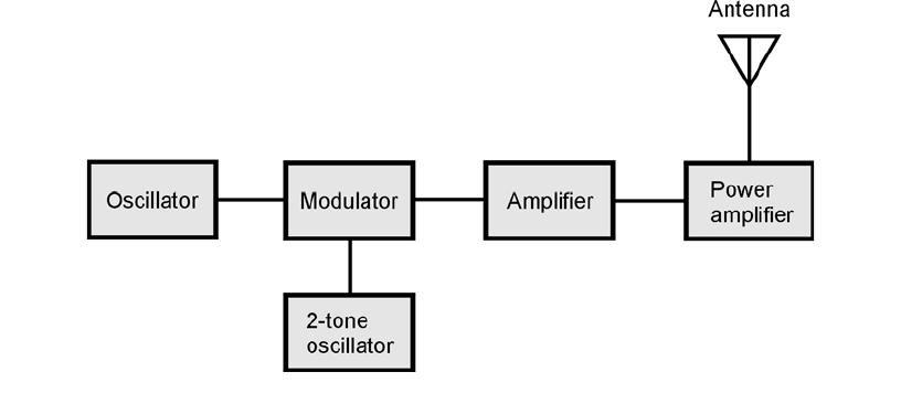
18. The arrangement in the block diagram of Fig. 24-20 represents
(a) a waveform analyzer.
(b) an audio oscillator.
(c) an RF oscillator.
(d) a sine wave generator.
19. A tuned RF PA must always be
(a) set to work over a wide range of frequencies.
(b) adjusted for maximum power output.
(c) operated at an even harmonic of the input frequency.
(d) operated in class C.
Quiz 405
24-20 Illustration for Quiz Question 18.
20. Class B amplification can be used to obtain low distortion for audio applications
(a) by connecting two amplifiers in cascade, thereby maximizing the gain and generating a
pure sine wave output.
(b) by biasing the bipolar transistor or FET beyond cutoff or pinchoff, thereby ensuring that
the output is in phase with the input.
(c) by connecting two identical bipolar transistors or FETs, biased exactly at cutoff or
pinchoff, in a push-pull configuration.
(d) by biasing the bipolar transistor or FET in the middle of the straight-line portion of the
characteristic curve.
406 Amplifiers and Oscillators
IN RADIO OR WIRELESS COMMUNICATIONS, A TRANSMITTER CONVERTS DATA INTO ELECTROMAGNETIC
(EM) waves intended for recovery by one or more receivers. In this chapter, we’ll look at how data is
converted to EM waves and transmitted, and then examine how the resulting EM fields can be in-
tercepted and received.
Oscillation and Amplification
A radio transmitter employs one or more oscillators to generate an RF signal, and amplifiers to gen-
erate the required power output. You just learned how these circuits work. Most transmitters have
mixers in addition to the oscillating and amplifying stages. Signal mixing is commonly done with
diodes, and was discussed in Chap. 20.
Modulation
Modulation is the process of writing data onto an electric current or EM wave. The process can be
done by varying the amplitude, the frequency, or the phase of the current or wave. Another method
is to transmit a series of pulses, whose duration, amplitude, or spacing is made to vary.
The Carrier
The heart of a wireless signal is a sine wave known as the carrier. The lowest carrier frequency used
for radio communications is a few kilohertz (kHz). The highest frequency is in the hundreds of giga-
hertz (GHz). For efficient data transfer, the carrier frequency must be at least 10 times the highest
frequency of the modulating signal.
On/Off Keying
The simplest form of modulation is on/off keying. This can be done in the oscillator of a radio
transmitter to send Morse code, which is a binary digital mode. The duration of a Morse-code dot
is one bit (binary digit). A dash is 3 bits long. The space between dots and dashes within a charac-
407
25
CHAPTER
Wireless Transmitters
and Receivers
Copyright © 2006, 2002, 1997, 1993 by The McGraw-Hill Companies, Inc. Click here for terms of use.
ter is 1 bit. The space between characters in a word is 3 bits. The space between words is
7 bits. The key-down (full-carrier) condition is called mark, and the key-up (no-signal) condition
is called space.
Morse code is slow. Human operators use speeds ranging from about 5 words per minute
(wpm) to 40 or 50 wpm. A few human operators can work at 60 to 70 wpm. These people usually
copy the signals in their heads.
Frequency-Shift Keying
Digital data can be sent over wireless links by means of frequency-shift keying (FSK). In some FSK
systems, the carrier frequency is shifted between mark and space conditions, usually by a few hun-
dred hertz or less. In other systems, a two-tone audio-frequency (AF) sine wave modulates the car-
rier. This is known as audio-frequency-shift keying (AFSK).
The two most common codes used with FSK and AFSK are Baudot (pronounced “baw-DOE”)
and ASCII (pronounced “ASK-ee”). The acronym ASCII stands for American Standard Code for In-
formation Interchange.
In radioteletype (RTTY) FSK and AFSK systems, a terminal unit (TU) converts the digital sig-
nals into electrical impulses that operate a teleprinter or display characters on a computer screen.
The TU also generates the signals necessary to send RTTY as an operator types on a keyboard. A de-
vice that sends and receives AFSK is sometimes called a modem. This acronym stands for modulator/
demodulator. A modem is basically the same as a TU. Figure 25-1 is a block diagram of an AFSK
transmitter.
The main advantage of FSK or AFSK over on/off keying is the fact that there are fewer errors
or misprints, because the space part of the signal is identified as such, rather than existing as a gap
or pause in the data. A sudden noise burst in an on/off keyed signal can confuse a receiver into read-
ing the space as a mark signal, but when the space is positively represented by its own signal, this is
less likely to happen.
408 Wireless Transmitters and Receivers
25-1 Simplified block diagram of an AFSK transmitter.
Amplitude Modulation
An AF voice signal has frequencies mostly in the range between 300 Hz and 3 kHz. Some charac-
teristic of an RF carrier can be varied, or modulated, by these waveforms, thereby transmitting voice
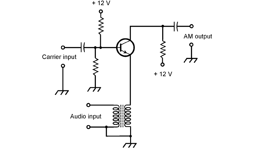
information. Figure 25-2 shows a simple circuit for obtaining amplitude modulation (AM). This cir-
cuit can be imagined as an RF amplifier for the carrier, with the instantaneous gain dependent on
the instantaneous audio input amplitude. Another way to think of this circuit is as a mixer that
combines the RF carrier and audio signals to produce sum and difference signals at frequencies just
above and below that of the carrier.
The circuit shown in Fig. 25-2 works well, provided the AF input amplitude is not too great. If
the AF input is excessive, then distortion occurs, intelligibility is degraded, system efficiency is re-
duced, and the bandwidth of the signal is increased unnecessarily.
The extent of AM is expressed as a percentage, from 0 percent (an unmodulated carrier) to
100 percent (full modulation). Increasing the modulation past 100 percent causes the same prob-
lems as excessive AF input. In an AM signal modulated 100 percent,
1
⁄3 of the power is used to convey
the data, and the other
2
⁄3 is consumed by the carrier wave.
Figure 25-3 shows a spectral display of an AM voice radio signal. The horizontal scale is cali-
brated in increments of 1 kHz per division. Each vertical division represents 3 dB of change in sig-
nal strength. The maximum (reference) amplitude is 0 dB relative to 1 mW (abbreviated as 0 dBm).
The data exists in sidebands above and below the carrier frequency. These sidebands resemble the
sum and difference signals produced by a mixer. In this case the mixing occurs between the AF input
signal and the RF carrier. The RF between −3 kHz and the carrier frequency constitutes the lower
Modulation 409
25-2 An amplitude modulator using an NPN bipolar transistor.
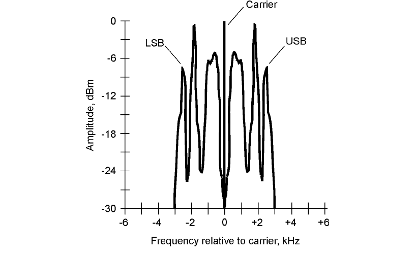
sideband (LSB); the RF from the carrier frequency to +3 kHz represents the upper sideband (USB).
The bandwidth is the difference between the maximum and minimum sideband frequencies, in this
case 6 kHz.
In an AM signal, the bandwidth is twice the highest audio modulating frequency. In the exam-
ple of Fig. 25-3, all the voice energy is at or below 3 kHz, so the signal bandwidth is 6 kHz. This is
typical of a communications signal. In standard AM broadcasting, the AF energy is spread over a
wider bandwidth, nominally 10 kHz.
Single Sideband
In AM, most of the RF signal power is consumed by the carrier alone; the two sidebands are mirror-
image duplicates. This is inefficient, and is also unnecessarily redundant! If the carrier and one of
the sidebands is eliminated, these shortcomings can be overcome. That makes the signal stronger for
a given amount of RF power, or allows the use of lower RF power in a given communications sce-
nario. Another bonus is the fact that the bandwidth is reduced to less than half that of an AM sig-
nal modulated with the same data, so more than twice as many signals can fit into a specific range,
or band, of frequencies.
When the carrier is removed from an AM signal along with one of the sidebands, the remain-
ing RF energy has a spectral display resembling Fig. 25-4. This is single sideband (SSB) transmission.
Either the LSB or the USB alone can be used, with equally good results.
410 Wireless Transmitters and Receivers
25-3 Spectral display of a typical AM voice
communications signal.
