Gibilisco S. Teach Yourself Electricity and Electronics
Подождите немного. Документ загружается.

Find the ratio P
out
/P
in
= 125/5.03 = 24.85... . Then find the logarithm: log 24.85...=
1.395... . Finally, multiply by 10 and round off. The gain is thus 10 × 1.395...= 14.0 dB.
Problem 24-4
Suppose an attenuator (a circuit designed deliberately to produce power loss) provides 10 dB power
reduction. The input power is 94 W. What is the output power?
An attenuation of 10 dB represents a gain of −10 dB. We know that P
in
= 94 W, so the un-
known in the power gain formula is P
out
. We must solve for P
out
in this formula:
−10 = 10 log (P
out
/94)
First, divide each side by 10, getting:
−1 = log (P
out
/94)
To solve this, we must take the base-10 antilogarithm, also known as the antilog, or the inverse log, of
each side. The antilog function undoes the log function. The antilog of a value x is written antilog
x. It can also be denoted as log
−1
x or 10
x
. Antilogarithms can be determined with any good scientific
calculator. The solution process goes like this:
antilog (−1) = antilog [log (P
out
/94)]
0.1 = P
out
/94
94 × 0.1 = P
out
P
out
= 9.4 W
Decibels and Impedance
When determining the voltage gain (or loss) and the current gain (or loss) for a circuit in decibels,
you should expect to get the same figure for both parameters only when the input impedance is
identical to the output impedance. If the input and output impedances differ, the voltage gain or
loss is generally not the same as the current gain or loss.
Consider how transformers work. A step-up transformer, in theory, has voltage gain, but
this alone doesn’t make a signal more powerful. A step-down transformer can exhibit theoretical
current gain, but again, this alone does not make a signal more powerful. In order to make a sig-
nal more powerful, a circuit must increase the signal power—the product of the voltage and the
current!
When determining power gain (or loss) for a particular circuit in decibels, the input and out-
put impedances don’t matter. In this sense, positive power gain always represents a real-world increase
in signal strength. Similarly, negative power gain (or power loss) always represents a true decrease in
signal strength.
Basic Bipolar Transistor Amplifier
In the previous chapters, you saw some circuits that use bipolar and field effect transistors. A signal
can be applied to some control point, causing a much greater signal to appear at the output. This is
the principle by which all amplifiers work.
Basic Bipolar Transistor Amplifier 381
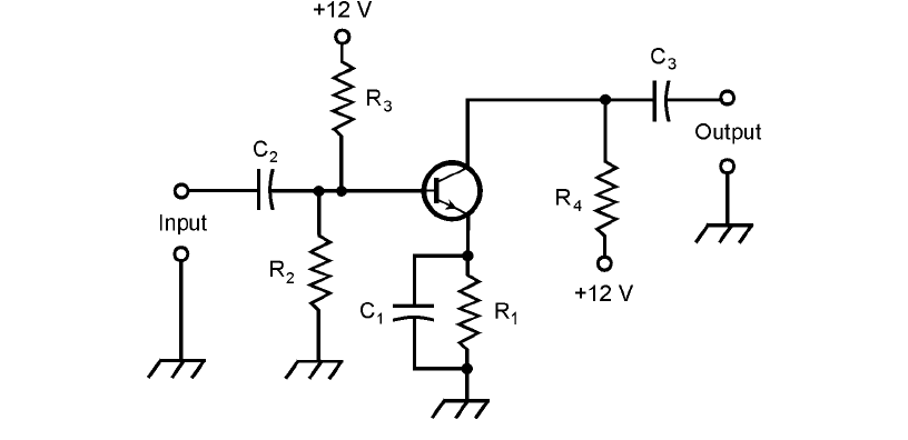
In Fig. 24-1, an NPN bipolar transistor is connected as a common emitter amplifier. The input
signal passes through C
2
to the base. Resistors R
2
and R
3
provide the base bias. Resistor R
1
and ca-
pacitor C
1
allow for the emitter to have a dc voltage relative to ground, while keeping it grounded
for signals. Resistor R
1
also limits the current through the transistor. The ac output signal goes
through capacitor C
3
. Resistor R
4
keeps the ac output signal from being short-circuited through the
power supply.
In this amplifier, the optimum capacitance values depend on the design frequency of the am-
plifier, and also on the impedances at the input and output. In general, as the frequency and/or cir-
cuit impedance increase, less capacitance is needed. At audio frequencies and low impedances, the
capacitors might be as large as 100 µF. At radio frequencies and high impedances, values will be only
a fraction of a microfarad, down to picofarads at the highest frequencies and impedances. The op-
timum resistor values also depend on the application. In the case of a weak-signal amplifier, typical
values are 470 Ω for R
1
, 4.7 kΩ for R
2
, 10 kΩ for R
3
, and 4.7 kΩ for R
4
.
Basic JFET Amplifier
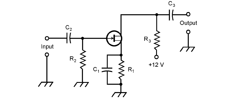
Figure 24-2 shows an N-channel JFET hooked up as a common source amplifier. The input signal
passes through C
2
to the gate. Resistor R
2
provides the bias. Resistor R
1
and capacitor C
1
give the
source a dc voltage relative to ground, while grounding it for signals. The output signal goes
through C
3
. Resistor R
3
keeps the output signal from being short-circuited through the power
supply.
A JFET has a high input impedance, and therefore the value of C
2
should usually be small. If
the device is a MOSFET, the input impedance is higher still, and C
2
will be smaller yet, sometimes
1 pF or less. The resistor values depend on the application. In some instances, R
1
and C
1
are not
used, and the source is grounded directly. If R
1
is used, its optimum value will depend on the input
382 Amplifiers and Oscillators
24-1 An amplifier circuit with a bipolar transistor. Component
designators are discussed in the text.
impedance and the bias needed for the FET. For a weak-signal amplifier, typical values are 680 Ω
for R
1
, 10 kΩ for R
2
, and 100 Ω for R
3
.
Amplifier Classes
Amplifier circuits can be categorized as class A, class AB, class B, and class C. Each class has its own
special characteristics, and works best in its own unique set of applications.
The Class A Amplifier
With the previously mentioned component values, the amplifier circuits in Figs. 24-1 and 24-2 op-
erate in class A. This type of amplifier is linear, meaning that the output waveform has the same
shape as (although a much greater amplitude than) the input waveform.
For class A operation with a bipolar transistor, the bias must be such that, with no signal input,
the device is near the middle of the straight-line portion of the I
C
versus I
B
(collector current versus
base current) curve. This is shown for an NPN transistor in Fig. 24-3. For PNP, reverse the polarity
signs. With a JFET or MOSFET, the bias must be such that, with no signal input, the device is near
the middle of the straight-line part of the I
D
versus E
G
(drain current versus gate voltage) curve. This
is shown in Fig. 24-4 for an N-channel JFET. For P channel, reverse the polarity signs.
In a class A amplifier, it is important that the input signal not be too strong. An excessively
strong input signal will drive the device out of the straight-line part of the characteristic curve dur-
ing part of the cycle. When this occurs, the output waveshape will not be a faithful reproduction of
the input waveshape, and the amplifier will become nonlinear. Class A amplifiers are supposed to
operate in a linear fashion at all times.
The Class AB Amplifier
Class A operation is inefficient because the transistor draws current whether there is a signal input
or not. For weak-signal work, efficiency is not too critical; the things that matter are the gain and
Amplifier Classes 383
24-2 An amplifier circuit with an FET. Component designators are
discussed in the text.

the sensitivity. In power amplifiers, efficiency is more important, and gain and sensitivity don’t mat-
ter as much.
When a bipolar transistor is biased close to cutoff under no-signal conditions, or when an FET
is near pinchoff, the input signal always drives the device into the nonlinear part of the operating
curve. Typical bias zones for class AB are shown in Figs. 24-3 and 24-4. A small collector or drain
current flows when there is no input, but it is less than the no-signal current that flows in a class A
amplifier. This is called class AB operation. It’s more efficient than class A, but the gain and sensitiv-
ity are not as high.
There are two modes of class AB amplification. If the bipolar transistor or FET is never driven
into cutoff/pinchoff during any part of the signal cycle, the amplifier is working in class AB
1
. If the
device goes into cutoff pinchoff for any part of the cycle (up to almost half), the amplifier is work-
ing in class AB
2
.
In a class AB amplifier, the output signal waveform is not identical with the input signal wave-
form. But if the signal wave is modulated, such as in a voice radio transmitter, the waveform of the
modulating signal comes out undistorted anyway. Thus, class AB operation is useful in RF power
amplifiers.
384 Amplifiers and Oscillators
24-4 Various classes of
amplifier operation for
an N-channel JFET.
24-3 Various classes of
amplifier operation for
an NPN bipolar
transistor.
The Class B Amplifier
When a bipolar transistor is biased exactly at cutoff, or an FET is biased exactly at pinchoff under
zero-input-signal conditions, an amplifier is working in class B. These operating points are la-
beled on the curves in Figs. 24-3 and 24-4. The class B scheme lends itself well to RF power am-
plification.
In class B operation, there is no collector or drain current when there is no signal. This saves
energy, because the circuit does not consume power unless there is a signal going into it. (Class A
and class AB amplifiers consume some power even when the input is zero.) When there is an
input signal, current flows in the device during exactly half of the cycle. The output signal wave-
form is greatly different from the input waveshape in a class B amplifier. In fact, it is half-wave
rectified.
You’ll sometimes hear of class AB or class B “linear amplifiers,” especially in ham radio. The
term “linear” refers to the fact that the modulation waveform is not distorted by such an amplifier,
even though the carrier waveform is distorted because the transistor is not biased in the straight-line
part of the operating curve.
Class AB
2
and class B amplifiers draw power from the input signal source. Engineers say that
such amplifiers require a certain amount of drive or driving power to function. Class A and class AB
1
amplifiers theoretically need no driving power, although there must be an input voltage.
The Class B Push-Pull Amplifier
Sometimes two bipolar transistors or FETs are used in a class B circuit, one for the positive half of
the cycle and the other for the negative half. In this way, signal waveform distortion is eliminated.
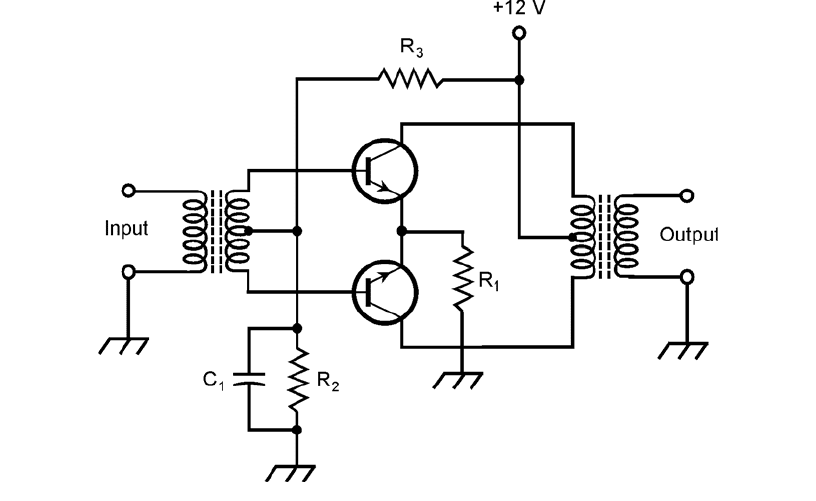
This is called a class B push-pull amplifier. This type of circuit, using two NPN bipolar transistors, is
illustrated in Fig. 24-5. Resistor R
1
limits the current through the transistors. Capacitor C
1
keeps the
input transformer center tap at signal ground, while allowing for some dc base bias. Resistors R
2
and
R
3
bias the transistors precisely at their cutoff points. The two transistors must be identical. Not
only should their part numbers be the same, but ideally they should be chosen by experiment to en-
sure that their characteristic curves are as closely matched as possible.
Class B push-pull is a popular arrangement for audio-frequency (AF) power amplification. It
combines the efficiency of class B with the low distortion of class A. Its main disadvantage is that it
needs two center-tapped transformers, one at the input and the other at the output. This makes
push-pull amplifiers rather bulky and expensive compared to other types.
The Class C Amplifier
A bipolar transistor or FET can be biased past cutoff or pinchoff, and it will still work as a power
amplifier (PA), provided that the drive is sufficient to overcome the bias during part of the cycle.
This is known as class C operation. Bias points for class C are labeled in Figs. 24-3 and 24-4.
Class C amplifiers are nonlinear, even for amplitude modulation waveforms. Because of this, a
class C circuit is useful only for signals that are either full-on or full-off. Such signals include old-
fashioned Morse code, and digital schemes in which the frequency or phase (but not the amplitude)
of the signal is varied.
A class C amplifier needs a lot of driving power. The gain is low. For example, it might take
300 W of signal drive to get 1 kW of signal power output. However, the efficiency is better than
that of class A, AB, or B amplifiers. Let’s take a closer look, now, at what amplifier efficiency is all
about.
Amplifier Classes 385
Efficiency in Power Amplifiers
In power amplification, efficiency is important. It not only provides optimum output power with
minimum heat generation and minimum strain on the transistors, but it conserves energy as well.
This translates into reduced cost, reduced size and weight, and longer equipment life compared with
inefficient power amplifiers.
Determining dc Power Input
Suppose you connect an ammeter or milliammeter in series with the collector or drain of an ampli-
fier and the power supply. While the amplifier is in operation, this meter will have a certain reading.
The reading might appear constant, or it might fluctuate with changes in the input signal level. The
dc collector power input to a bipolar-transistor amplifier circuit is the product of the collector current
(I
C
) and the collector voltage (E
C
). Similarly, for an FET, the dc drain power input is the product of
the drain current (I
D
) and the drain voltage (E
D
). These power figures can be further categorized as
average or peak values. This discussion involves only average power.
The dc collector or drain power input can be high even when there is no input signal applied
to an amplifier. A class A circuit operates this way. In fact, when a signal is applied to a class A am-
plifier, the meter reading, and therefore the dc collector or drain power input, does not change com-
pared to the value under conditions of no input signal. In class AB
1
or class AB
2
, there is low current
(and therefore low dc collector or drain power input) with zero input signal, and a higher current
386 Amplifiers and Oscillators
24-5 A class B push-pull amplifier using NPN bipolar transistors.
Component designators are discussed in the text.
(and therefore a higher dc power input) with an input signal. In class B and class C, there is no cur-
rent (and therefore zero dc collector or drain power input) when there is no input signal. The cur-
rent, and therefore the dc power input, increases with increasing signal input. The dc collector or
drain power input is usually measured in watts, the product of amperes and volts. It can be indicated
in milliwatts for low-power amplifiers, or kilowatts for high-power amplifiers.
Power Output
The power output of an amplifier must be measured by means of a specialized ac wattmeter. The de-
sign of AF and RF wattmeters is a sophisticated specialty in engineering.
When there is no signal input to an amplifier, there is no signal output, and therefore the power
output is zero. This is true no matter what the class of amplification. The greater the signal input,
in general, the greater the power output of a power amplifier, up to a certain point.
Power output, like dc input, is measured in watts. For very low power circuits, it can be in mil-
liwatts; for high-power circuits, it is sometimes given in kilowatts.
Definition of Efficiency
The efficiency of a power amplifier is the ratio of the ac power output to the dc collector or drain
power input.
In a bipolar-transistor amplifier, let P
C
be the dc collector power input, and let P
out
be the ac
power output. For an FET amplifier, let P
D
be the dc drain power input, and let P
out
be the ac power
output. Then the efficiency, eff, of the bipolar transistor amplifier is given by:
eff = P
out
/P
C
For the FET circuit, the efficiency is:
eff = P
out
/P
D
These are ratios, and they are always between 0 and 1. Efficiency is often expressed as a percentage
instead of a ratio, so the preceding formulas are modified as follows:
eff
%
= 100 P
out
/P
C
and
eff
%
= 100 P
out
/P
D
Problem 24-5
Suppose a bipolar-transistor amplifier has a dc collector input of 115 W and an ac power output of
65.0 W. What is the efficiency in percent?
Use the formula for the efficiency of a bipolar transistor amplifier expressed as a percentage:
eff
%
= 100 P
out
/P
C
= 100 × 65/115 = 100 × 0.565 = 56.5%.
Problem 24-6
Suppose an FET amplifier is 60 percent efficient. If the power output is 3.5 W, what is the dc drain
power input?
Efficiency in Power Amplifiers 387
Plug in values to the formula for the efficiency of an FET amplifier expressed as a percentage.
The resulting equation is solved as follows:
60 = 100 × 3.5/P
D
60 = 350/P
D
60/350 = 1/P
D
P
D
= 350/60
= 5.8 W
Efficiency versus Class
Class A amplifiers have efficiency figures from 25 percent to 40 percent, depending on the nature
of the input signal and the type of transistor used. A good class AB
1
amplifier is 35 percent to
45 percent efficient. A class AB
2
amplifier, if well designed and properly operated, can be up to about
50 percent efficient. Class B amplifiers are typically 50 percent to 65 percent efficient. Class C am-
plifiers can have efficiency levels as high as 75 percent.
Drive and Overdrive
Class A and AB
1
power amplifiers do not, in theory, take any power from the signal source to pro-
duce significant output power. This is one of the advantages of these classes of operation. It is only
necessary that a certain voltage be present at the control electrode (the base, gate, emitter, or source)
for these circuits to produce useful output signal power. Class AB
2
amplifiers need some driving
power to produce ac power output. Class B amplifiers require more drive than class AB
2
, and class
C amplifiers need still more drive.
Whatever kind of PA is used in a given situation, it is important that the driving signal not be
too strong. If overdrive takes place, distortion occurs in the output signal. An oscilloscope can be
used to determine whether or not an amplifier is being overdriven. The scope is connected to the
amplifier output terminals, and the waveform of the output signal is examined. The output wave-
form for a particular class of amplifier always has a characteristic shape. Overdrive is indicated by a
form of distortion known as flat topping.
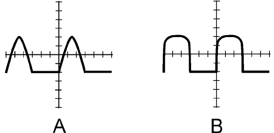
In Fig. 24-6A, the output signal waveshape for a properly operating class B amplifier is shown.
In Fig. 24-6B, the output of an overdriven class B amplifier is shown. Note that the peaks are
blunted or truncated. The result of this can be distortion in the modulation on a radio signal, and
388 Amplifiers and Oscillators
24-6 At A, an oscilloscope
display of the signal
output waveform from
a properly operating
class B power
amplifier. At B, a
display showing
distortion in the
waveform caused by
overdrive.
also an excessive amount of signal output at harmonic frequencies. The efficiency of the circuit can
be degraded, as well. The flat tops of the distorted waves don’t contribute anything to the strength
of the signal at the desired frequency, but they cause a higher-than-normal dc power input, which
translates into a lower-than-normal efficiency.
Audio Amplification
The circuits you’ve seen so far have been general, not application-specific. With capacitors of several
microfarads, and when biased for class A, these circuits are representative of audio amplifiers.
Frequency Response
High-fidelity audio amplifiers, of the kind used in music systems, must have more or less constant gain
from 20 Hz to 20 kHz. This is a frequency range of 1000:1. Audio amplifiers for voice communica-
tions must work from 300 Hz to 3 kHz, a 10:1 span of frequencies. In digital communications, audio
amplifiers are designed to work over a narrow range of frequencies, sometimes less than 100 Hz wide.
Hi-fi amplifiers are usually equipped with resistor-capacitor (RC) networks that tailor the fre-
quency response. These are tone controls, also called bass and treble controls. The simplest hi-fi am-
plifiers use a single knob to control the tone. More sophisticated amplifiers have separate controls,
one for bass and the other for treble. The most advanced hi-fi systems make use of graphic equaliz-
ers, having controls that affect the amplifier gain over several different frequency spans.
Volume Control
Audio amplifier systems usually consist of two or more stages. A stage is one bipolar transistor or
FET (or a push-pull combination), plus peripheral resistors and capacitors. Stages can be cascaded
one after the other to get high gain. In one of the stages in an audio system, a volume control is used.
This control can be as simple as a potentiometer that allows the gain of a stage to be adjusted with-
out affecting its linearity.
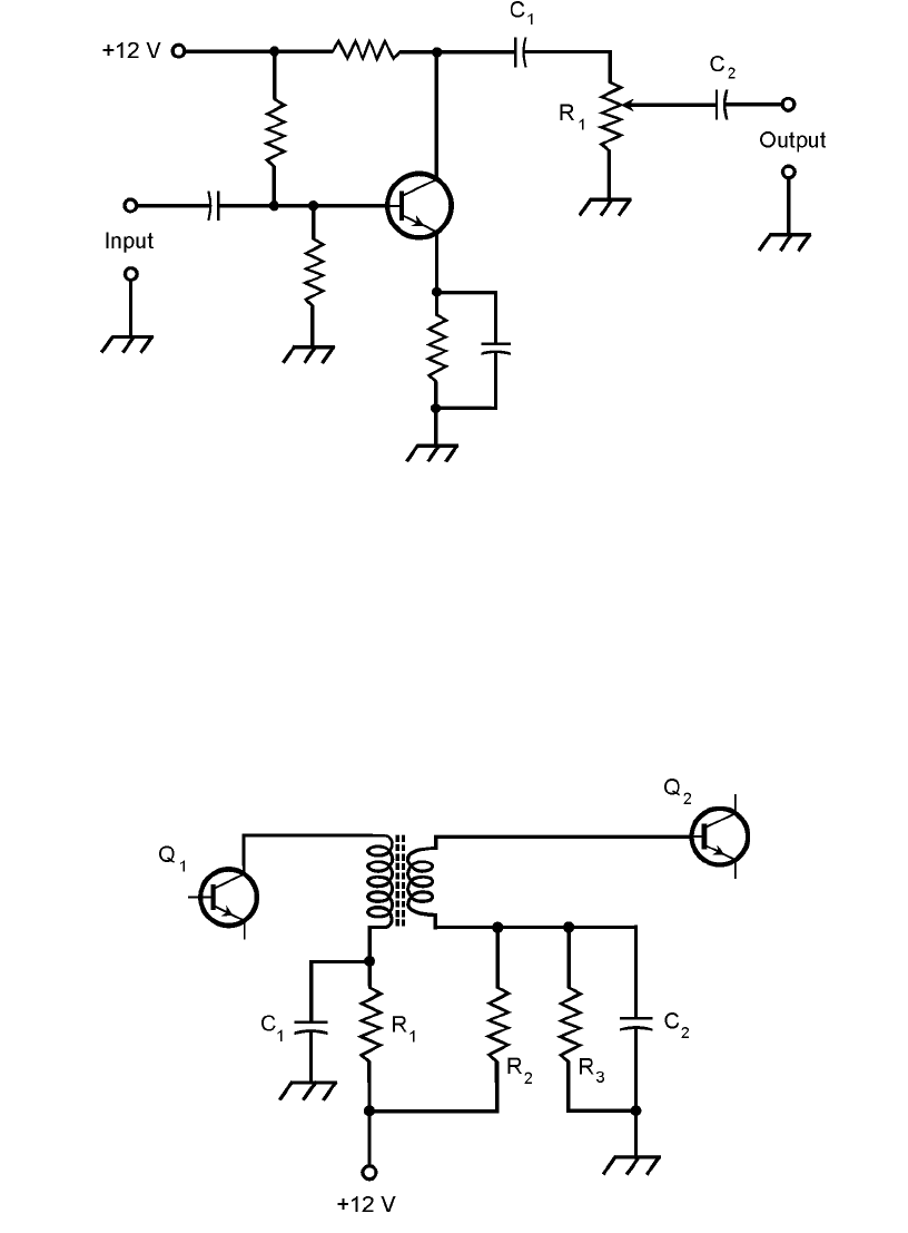
An example of a basic volume control is shown in Fig. 24-7. In this amplifier, the gain through
the transistor is constant. The ac output signal passes through C
1
and appears across R
1
, a poten-
tiometer. The wiper (indicated by the arrow) of the potentiometer picks off more or less of the ac
output signal, depending on the position of the control shaft. Capacitor C
2
isolates the potentiome-
ter from the dc bias of the following stage.
A volume control should normally be placed in a stage where the audio power level is low. This
allows the use of a low-wattage, low-cost potentiometer.
Transformer Coupling
Transformers can be used to transfer (or couple) signals from one stage to the next in a cascaded am-
plifier system (also known as an amplifier chain). An example of transformer coupling is shown in
Fig. 24-8. Capacitors C
1
and C
2
keep one end of the transformer primary and secondary at signal
ground. Resistor R
1
limits the current through the first transistor, Q
1
. Resistors R
2
and R
3
provide
the proper base bias for transistor Q
2
.
The main disadvantage of this scheme is that it costs more than capacitive coupling. But trans-
former coupling can provide an optimum signal transfer between amplifier stages. By selecting a
transformer with the correct turns ratio, the output impedance of Q
1
can be perfectly matched to
the input impedance of Q
2
.
Audio Amplification 389
Tuned-Circuit Coupling
In some amplifier systems that employ transformer coupling, capacitors are added across the pri-
mary and/or secondary of the transformer. This results in resonance at a frequency determined by
the capacitance and the transformer winding inductance. If the set of amplifiers is intended for use
at only one frequency (and this is often the case in RF systems), this method of coupling, called
390 Amplifiers and Oscillators
24-8 An example of transformer coupling between amplifier
stages. Component designators are discussed in the text.
24-7 A basic volume control (potentiometer R
1
) can be used to vary the gain in a
low-power audio amplifier.
