Gibilisco S. Teach Yourself Electricity and Electronics
Подождите немного. Документ загружается.

17. If a fuse blows, and it is replaced with one having a lower current rating, there is a good
chance that
(a) the power supply will be severely damaged.
(b) the diodes will not rectify.
(c) the fuse will blow out right away.
(d) transient suppressors won’t work.
18. Suppose you see a fuse with nothing but a straight wire inside. You can assume that this fuse
(a) is a slow-blow type.
(b) is a quick-break type.
(c) has a low current rating.
(d) has a high current rating.
19. In order to minimize the risk of diode destruction as a result of surge currents that can occur
when a power supply is first switched on, which of the following techniques can be useful?
(a) Connecting multiple diodes in parallel, with low-value resistors in series with each diode
(b) Connecting multiple diodes in parallel, with low-value capacitors in series with each
diode
(c) Connecting multiple diodes in series, with low-value chokes across each diode
(d) Connecting multiple diodes in series, with low-value resistors across each diode
20. To repair a damaged power supply with which you are not completely familiar, you should
(a) install bleeder resistors before beginning your work.
(b) remove the fuse before beginning your work.
(c) leave it alone and have a professional work on it.
(d) short out all the diodes before beginning your work.
Quiz 351
THE WORD TRANSISTOR IS A CONTRACTION OF “CURRENT-TRANSFERRING RESISTOR.” A BIPOLAR
transistor has two P-N junctions. There are two configurations: a P-type layer sandwiched between
two N-type layers, or an N-type layer between two P-type layers.
NPN versus PNP
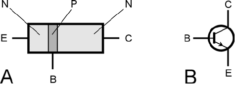
A simplified drawing of an NPN bipolar transistor is shown in Fig. 22-1A, and the schematic sym-
bol is shown in Fig. 22-1B. The P-type, or center, layer is called the base. One of the N-type semi-
conductor layers is the emitter, and the other is the collector. Sometimes these are labeled B, E, and
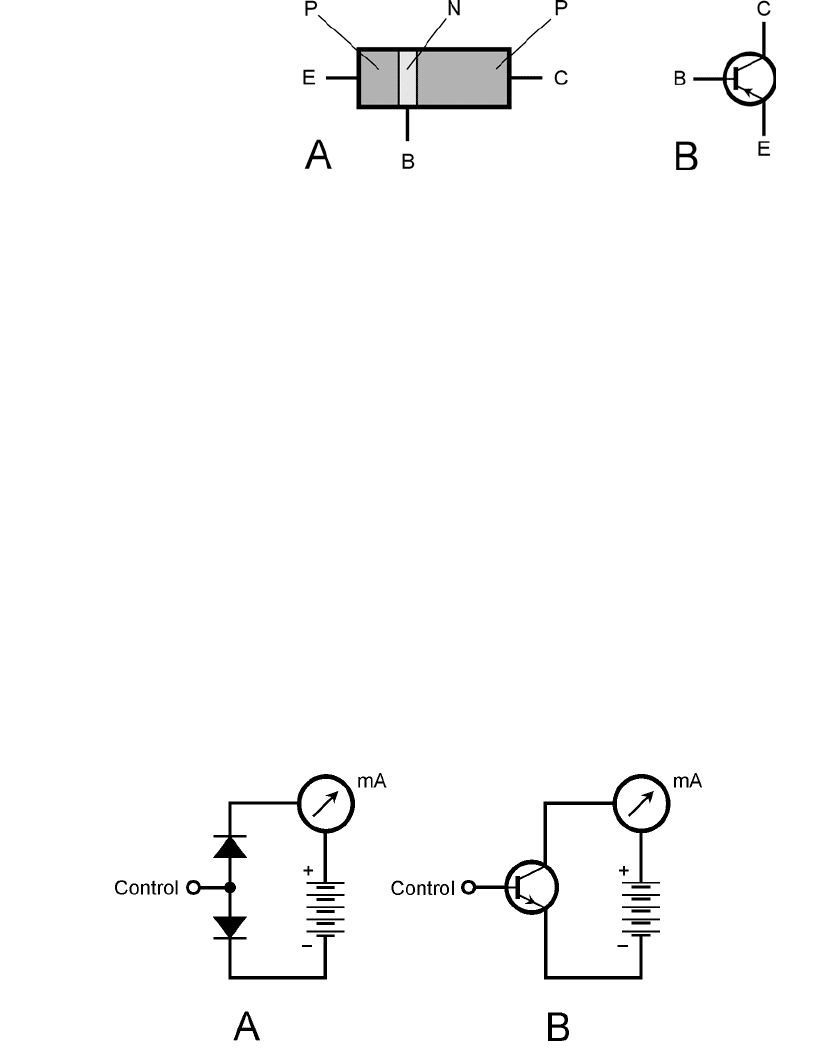
C in schematic diagrams. A PNP bipolar transistor has two P-type layers, one on either side of a thin
N-type layer (Fig. 22-2A). The schematic symbol is shown in Fig. 2-22B.
It’s easy to tell whether a bipolar transistor in a diagram is NPN or PNP. If the device is NPN,
the arrow at the emitter points outward. If the device is PNP, the arrow at the emitter points in-
ward.
Generally, PNP and NPN transistors can perform the same functions. The differences are the
polarities of the voltages and the directions of the resulting currents. In most applications, an NPN
device can be replaced with a PNP device or vice versa, the power-supply polarity can be reversed,
and the circuit will work in the same way—as long as the new device has the appropriate specifi-
cations.
352
22
CHAPTER
The Bipolar Transistor
22-1 At A, pictorial diagram
of an NPN transistor.
At B, the schematic
symbol. Electrodes are
E = emitter, B = base,
and C = collector.
Copyright © 2006, 2002, 1997, 1993 by The McGraw-Hill Companies, Inc. Click here for terms of use.
Biasing
Imagine a bipolar transistor as consisting of two diodes in reverse series. You can’t normally con-
nect two diodes this way and get a working transistor, but the analogy is good for modeling the
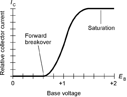
behavior of bipolar transistors. A dual-diode NPN transistor model is shown in Fig. 22-3A. The
base is formed by the connection of the two anodes. The emitter is one of the cathodes, and
the collector is the other cathode. Figure 22-3B shows the equivalent real-world NPN transistor
circuit.
The NPN Case
The normal method of biasing an NPN transistor is to have the collector voltage positive with re-
spect to the emitter. This is shown by the connection of the battery in Figs. 22-3A and 22-3B. Typ-
ical dc voltages for a transistor power supply range between 3 V and about 50 V. A typical voltage
is 12 V.
In the model and also in the real-world transistor circuit, the base is labeled “control,” because
the flow of current through the transistor depends critically on what happens at this electrode.
Zero Bias for NPN
Suppose the base of a transistor is at the same voltage as the emitter. This is known as zero bias.
When the forward bias is zero, the emitter-base current, often called simply base current and de-
Biasing 353
22-2 At A, pictorial diagram
of a PNP transistor.
At B, the schematic
symbol. Electrodes are
E = emitter, B = base,
and C = collector.
22-3 At A, the dual-diode model of a simple NPN circuit. At B, the
actual transistor circuit.
noted I
B
, is zero, and the emitter-base (E-B) junction does not conduct. This prevents current from
flowing between the emitter and collector, unless a signal is injected at the base to change the situ-
ation. Such a signal must, at least momentarily, attain a positive voltage equal to or greater than the
forward breakover voltage of the E-B junction.
Reverse Bias for NPN
Now imagine that a second battery is connected between the base and the emitter in the circuit of
Fig. 22-3B, with the polarity such that E
B
becomes negative with respect to the emitter. The addi-
tion of this new battery will cause the E-B junction to be reverse-biased. No current flows through
the E-B junction in this situation (as long as the new battery voltage is not so great that avalanche
breakdown occurs). A signal might be injected at the base to cause a flow of current, but such a sig-
nal must attain, at least momentarily, a positive voltage high enough to overcome both the reverse
bias and the forward breakover voltage of the junction.
Forward Bias for NPN
Now suppose that E
B
is made positive with respect to the emitter, starting at small voltages and grad-
ually increasing. This is forward bias. If the forward bias is less than the forward breakover voltage,
no current will flow. But as the base voltage E
B
reaches the breakover point, the E-B junction will
start to conduct.
The base-collector (B-C) junction of a bipolar transistor is normally reverse-biased. It will re-
main reverse-biased as long as E
B
is less than the supply voltage (in this case 12 V). In practical tran-
sistor circuits, it is common for E
B
to be set at a fraction of the supply voltage. Despite the reverse
bias of the B-C junction, a significant emitter-collector current, called collector current and denoted
I
C
, will flow once the E-B junction conducts.
In a real transistor circuit such as the one shown in Fig. 22-3B, the meter reading will jump
when the forward breakover voltage of the E-B junction is reached. Then even a small rise in E
B
, at-
tended by a rise in I
B
, will cause a large increase in I
C
, as shown in Fig. 22-4.
If E
B
continues to rise, a point will eventually be reached where the I
C
versus E
B
curve levels
off. The transistor is then said to be saturated or in saturation. It is wide open, conducting as much
as it can.
354 The Bipolar Transistor
22-4 Relative collector
current (I
C
) as a
function of base
voltage (E
B
) for a
hypothetical NPN
silicon transistor.
PNP Biasing
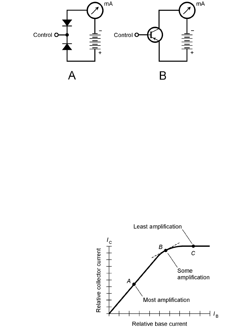
For a PNP transistor, the situation is a mirror image of the case for an NPN device. The diodes are
reversed, the arrow points inward rather than outward in the transistor symbol, and all the polari-
ties are reversed. The dual-diode PNP model, along with the real-world transistor circuit, are shown
in Fig. 22-5. In the preceding discussion, replace every occurrence of the word “positive” with the
word “negative.” Qualitatively, the same things happen: small changes in E
B
cause small changes in
I
B
, which in turn produce large fluctuations in I
C
.
Biasing for Amplification
Because a small change in I
B
causes a large variation in I
C
when the bias is just right, a transistor can
operate as a current amplifier. If you look at Fig. 22-6, you’ll see that there are some bias values at
which a transistor won’t provide any current amplification. If the transistor is in saturation, the I
C
Biasing for Amplification 355
22-5 At A, the dual-diode model of a simple PNP circuit. At B, the actual
transistor circuit.
22-6 Three different
transistor bias
points. The most
amplification is
obtained when the
bias is near the middle
of the straight-line
portion of the curve.
versus I
B
curve is horizontal. A small change in I
B
, in these portions of the curve, causes little or no
change in I
C
. But if the transistor is biased near the middle of the straight-line part of the curve in
Fig. 22-6, the transistor will work as a current amplifier.
The same situation holds for the curve in Fig. 22-4. At some bias points, a small change in E
B
does not produce much, if any, change in I
C
; at other points, a small change in E
B
produces a dra-
matic change in I
C
. Whenever we want a transistor to amplify a signal, it’s important that it be bi-
ased in such a way that a small change in the base current or voltage will result in a large change in
the collector current.
Static Current Amplification
Current amplification is often called beta by engineers. It can range from a factor of just a few times
up to hundreds of times. The beta of a transistor can be expressed as the static forward current trans-
fer ratio, abbreviated H
FE
. Mathematically, this is the collector current divided by the base current:
H
FE
= I
C
/I
B
For example, if a base current, I
B
, of 1 mA results in a collector current, I
C
, of 35 mA, then H
FE
=
35/1 = 35. If I
B
= 0.5 mA and I
C
= 35 mA, then H
FE
= 35/0.5 = 70. The H
FE
specification for a
particular transistor represents the greatest amount of current amplification that can be obtained
with it.
Dynamic Current Amplification
A more practical way to define current amplification is as the ratio of the difference in I
C
to the dif-
ference in I
B
that occurs when a small signal is applied to the base of a transistor. Abbreviate the
words “the difference in” by d. Then, according to this second definition:
Current amplification = dI
C
/dI
B
Figure 22-6 is a graph of the collector current as a function of the base current (I
C
versus I
B
)
for a hypothetical transistor. Three different points are shown, corresponding to three different bias
scenarios. The ratio dI
C
/dI
B
is different for each of the points in this graph. Geometrically, dI
C
/dI
B
at a given point is the slope of a line tangent to the curve at that point. The tangent line for point B
in Fig. 22-6 is a dashed straight line; the tangent lines for points A and C lie right along the curve
and are therefore not shown. The steeper the slope of the line, the greater is dI
C
/dI
B
. Point A pro-
vides the highest value of dI
C
/dI
B
, provided the input signal is not too strong. This value is very close
to H
FE
.
For small-signal amplification, point A in Fig. 22-6 represents a good bias level. Engineers
would say that it’s a good operating point. At point B, dI
C
/dI
B
is smaller than at point A, so point B
is not as good for small-signal amplification. At point C, dI
C
/dI
B
is practically zero. The transistor
won’t amplify much, if at all, if it is biased at this point.
Overdrive
Even when a transistor is biased for the greatest possible current amplification (at or near point A in
Fig. 22-6), a strong ac input signal can drive it to point B or beyond during part of the signal cycle.
356 The Bipolar Transistor
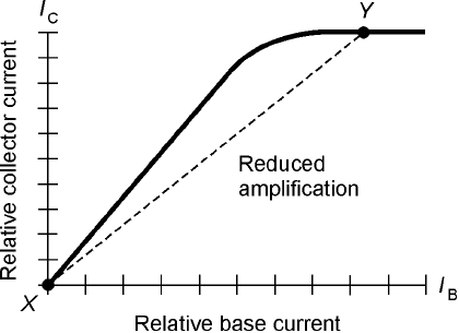
Then, dI
C
/dI
B
is reduced, as shown in Fig. 22-7. Points X and Y in the graph represent the instanta-
neous current extremes during the signal cycle in this particular case.
When conditions are like those in Fig. 22-7, a transistor amplifier will cause distortion in the
signal. This means that the output wave will not have the same shape as the input wave. This phe-
nomenon is known as nonlinearity. It can sometimes be tolerated, but often it is undesirable. When
the input signal to a transistor amplifier is too strong, the condition is called overdrive, and the am-
plifier is said to be overdriven.
Overdrive can cause problems other than signal distortion. An overdriven transistor is in or near
saturation during part of the input signal cycle. This reduces circuit efficiency, causes excessive col-
lector current, and can overheat the base-collector (B-C) junction. Sometimes overdrive can destroy
a transistor.
Gain versus Frequency
Another important specification for a transistor is the range of frequencies over which it can be used
as an amplifier. All transistors have an amplification factor, or gain, that decreases as the signal fre-
quency increases. Some devices work well only up to a few megahertz; others can be used to several
gigahertz.
Gain can be expressed in various ways. In the preceding discussion, you learned a little about
current gain, expressed as a ratio. You will also hear about voltage gain or power gain in amplifier
circuits. These, too, can be expressed as ratios. For example, if the voltage gain of a circuit is 15,
then the output signal voltage (rms, peak, or peak-to-peak) is 15 times the input signal voltage.
If the power gain of a circuit is 25, then the output signal power is 25 times the input signal
power.
Two expressions are commonly used for the gain-versus-frequency behavior of a bipolar transis-
tor. The gain bandwidth product, abbreviated f
T
, is the frequency at which the gain becomes equal to
1 with the emitter connected to ground. If you try to make an amplifier using a transistor at a fre-
quency higher than its f
T
specification, you are bound to fail. The alpha cutoff frequency of a transis-
tor is the frequency at which the gain becomes 0.707 times its value when the input signal frequency
is 1 kHz. A transistor can have considerable gain at its alpha cutoff frequency. By looking at this
Gain versus Frequency 357
22-7 Excessive input
reduces amplification.
specification for a particular transistor, you can get an idea of how rapidly it loses its ability to am-
plify as the frequency goes up. Some devices die off faster than others.
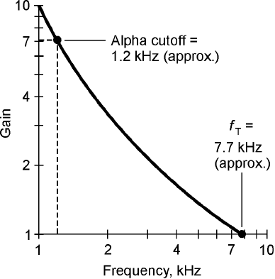
Figure 22-8 shows the gain bandwidth product and alpha cutoff frequency for a hypothetical
transistor, on a graph of gain versus frequency. Note that the scales of this graph are not linear; that
is, the divisions are not evenly spaced. This type of graph is called a log-log graph because both scales
are logarithmic rather than linear.
Common Emitter Circuit
A transistor can be hooked up in three general ways. The emitter can be grounded for signal, the
base can be grounded for signal, or the collector can be grounded for signal. An often-used arrange-
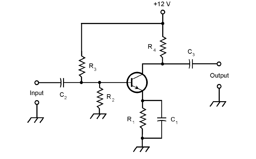
ment is the common emitter circuit. “Common” means “grounded for the signal.” The basic config-
uration is shown in Fig. 22-9.
A terminal can be at ground potential for a signal, and yet have a significant dc voltage. In the cir-
cuit shown, capacitor C
1
appears as a short circuit to the ac signal, so the emitter is at signal ground.
But resistor R
1
causes the emitter to have a certain positive dc voltage with respect to ground (or a neg-
ative voltage, if a PNP transistor is used). The exact dc voltage at the emitter depends on the resistance
of R
1
, and on the bias. The bias is set by the ratio of the values of resistors R
2
and R
3
. The bias can be
anything from zero, or ground potential, to +12 V, the supply voltage. Normally it is a couple of volts.
Capacitors C
2
and C
3
block dc to or from the input and output circuitry (whatever that might
be) while letting the ac signal pass. Resistor R
4
keeps the output signal from being shorted out
through the power supply. A signal enters the common emitter circuit through C
2
, where it causes
the base current, I
B
, to vary. The small fluctuations in I
B
cause large changes in the collector current,
I
C
. This current passes through resistor R
4
, causing a fluctuating dc voltage to appear across this re-
sistor. The ac part of this passes unhindered through capacitor C
3
to the output.
The circuit of Fig. 22-9 is the basis for many amplifiers, from audio frequencies through ultra-
high radio frequencies. The common emitter configuration produces the largest gain of any arrange-
ment. The output wave is 180° out of phase with respect to the input wave.
358 The Bipolar Transistor
22-8 Alpha cutoff and gain
bandwidth product
for a hypothetical
transistor.
Common Base Circuit
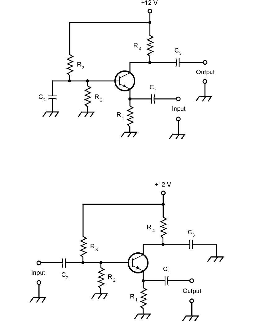
As its name implies, the common base circuit (Fig. 22-10) has the base at signal ground. The dc bias
is the same as for the common emitter circuit, but the input signal is applied at the emitter, instead
of at the base. This causes fluctuations in the voltage across R
1
, causing variations in I
B
. The result
of these small current fluctuations is a large change in the current through R
4
. Therefore, amplifica-
tion occurs. The output wave is in phase with the input wave.
The signal enters through capacitor C
1
. Resistor R
1
keeps the input signal from being shorted
to ground. Bias is provided by R
2
and R
3
. Capacitor C
2
keeps the base at signal ground. Resistor R
4
keeps the signal from being shorted out through the power supply. The output is taken through C
3
.
The common base circuit provides somewhat less gain than a common emitter circuit. How-
ever, it is more stable than the common emitter configuration in some applications, especially RF
power amplifiers.
Common Collector Circuit
A common collector circuit (Fig. 22-11) operates with the collector at signal ground. The input is ap-
plied at the base, just as it is with the common emitter circuit. The signal passes through C
2
onto
the base of the transistor. Resistors R
2
and R
3
provide the correct bias for the base. Resistor R
4
lim-
its the current through the transistor. Capacitor C
3
keeps the collector at signal ground. A fluctuat-
ing direct current flows through R
1
, and a fluctuating dc voltage therefore appears across it. The ac
Common Collector Circuit 359
22-9 Common emitter configuration. This diagram shows an NPN transistor
circuit.
360 The Bipolar Transistor
22-11 Common collector configuration, also known as an emitter follower.
This diagram shows an NPN transistor circuit.
22-10 Common base configuration. This diagram shows an NPN
transistor circuit.
