Gibilisco S. Teach Yourself Electricity and Electronics
Подождите немного. Документ загружается.

An SSB signal can be obtained with a balanced modulator, which is an amplitude modulator/
amplifier using two transistors with the inputs in push-pull and the outputs in parallel (Fig. 25-5).
This cancels the carrier wave in the output, leaving only LSB and USB energy. The result is a dou-
ble sideband suppressed carrier (DSBSC) signal, often called simply double sideband (DSB). At some
stage following the balanced modulator, one of the sidebands is removed from the DSB signal by a
bandpass filter to obtain an SSB signal.
Figure 25-6 is a block diagram of a simple SSB transmitter. The balanced modulator is placed
in a low-power section of the transmitter. The RF amplifiers that follow any type of amplitude mod-
ulator, including a balanced modulator, must all be linear to avoid distortion and unnecessary
spreading of signal bandwidth (“splatter”). They generally work in class A, except for the PA, which
works in class AB or class B.
Frequency and Phase Modulation
In frequency modulation (FM), the instantaneous amplitude of a signal remains constant, and
the instantaneous frequency is varied instead. A nonlinear PA such as a class C amplifier can be
used in an FM transmitter without causing signal distortion, because the amplitude does not
fluctuate.
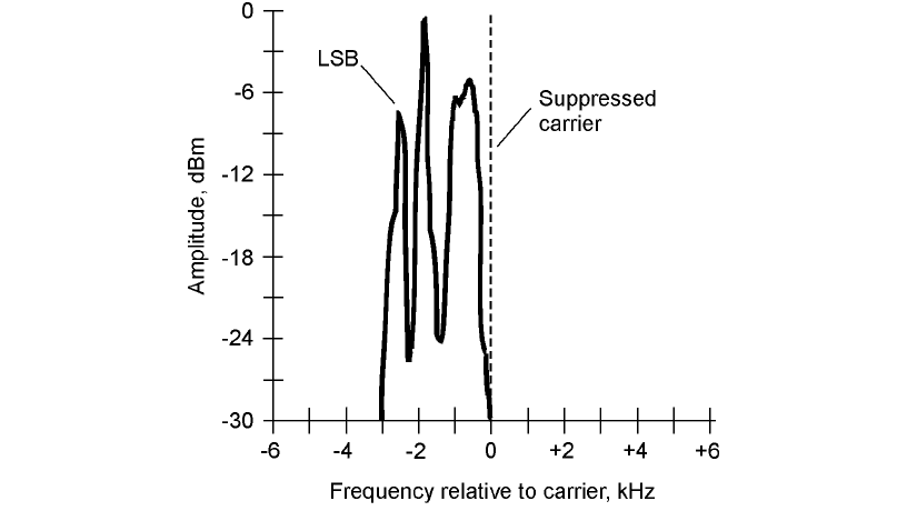
25-4 Spectral display of a typical SSB voice
communications signal. In this example, the carrier
and the USB energy are eliminated, leaving only the
LSB energy.
Modulation 411
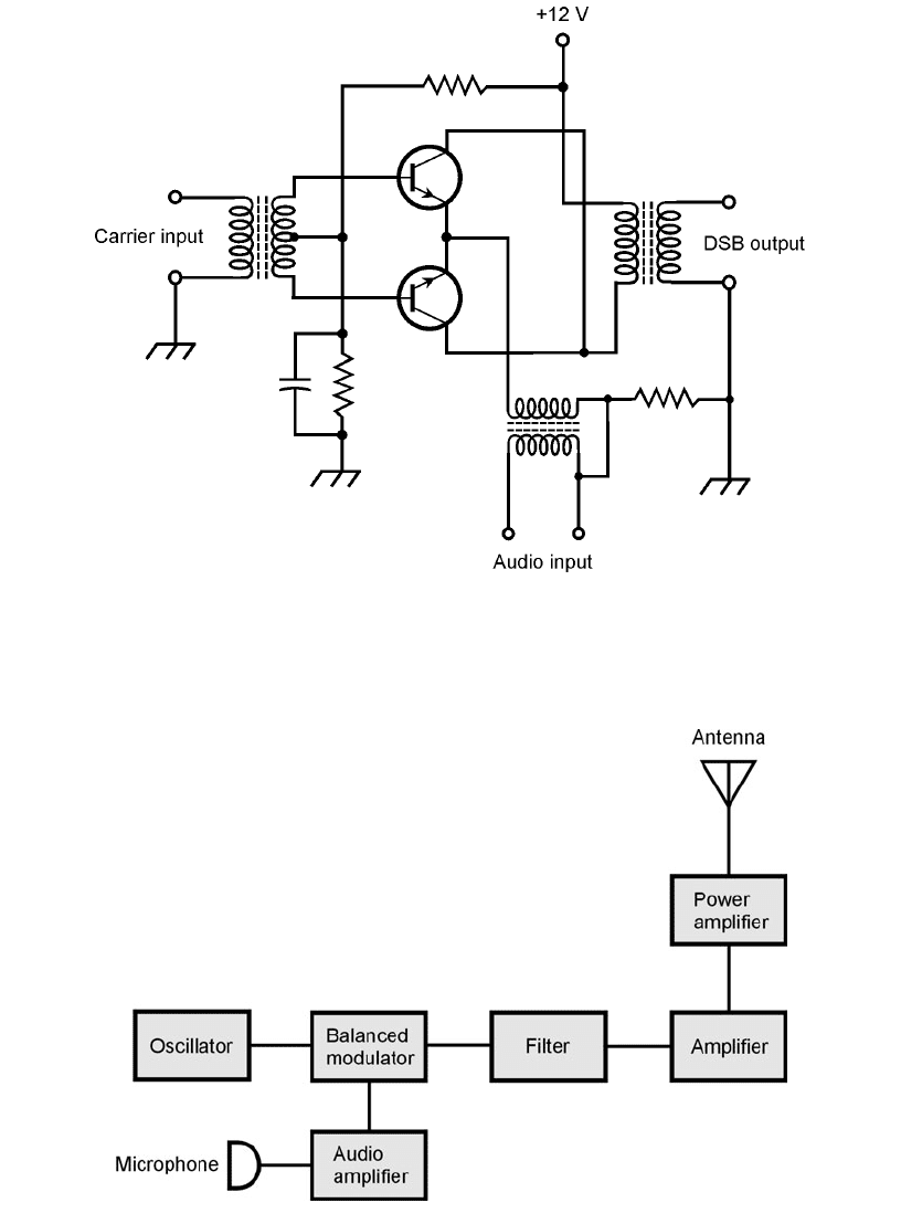
25-6 Block diagram of a basic SSB transmitter.
25-5 A balanced modulator using two NPN bipolar transistors. The inputs are in
push-pull, but the outputs are in parallel.
412 Wireless Transmitters and Receivers
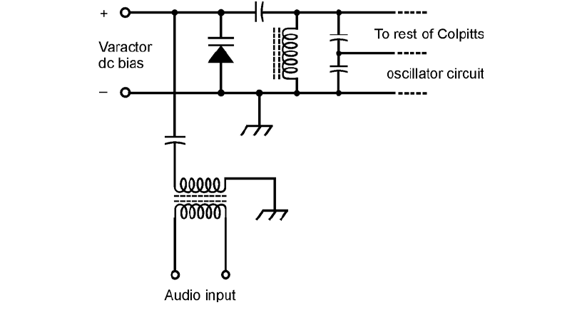
Frequency modulation can be obtained by applying the audio signal to a varactor in a tuned
oscillator. An example of this scheme, known as reactance modulation, is shown in Fig. 25-7.
The varying voltage across the varactor causes its capacitance to change in accordance with the
audio waveform. The changing capacitance results in variation of the resonant frequency of the
inductance-capacitance (LC) tuned circuit, causing small fluctuations in the frequency generated
by the oscillator.
Another way to get FM is to modulate the phase of the oscillator signal. This causes small vari-
ations in the frequency, because any instantaneous phase change shows up as an instantaneous fre-
quency change (and vice versa). When phase modulation is used, the audio signal must be processed,
adjusting the frequency response of the audio amplifiers. Otherwise the signal will sound unnatural
when it is received.
Deviation is the maximum extent to which the instantaneous-carrier frequency differs from the
unmodulated-carrier frequency. For most FM voice communications transmitters, the deviation is
standardized at ⫾5 kHz. This is known as narrowband FM (NBFM). The bandwidth of an NBFM
signal is comparable to that of an AM signal containing the same modulating information. In FM
hi-fi music broadcasting, and in some other applications, the deviation is much greater than
⫾5 kHz. This is called wideband FM (WBFM).
The deviation obtainable by means of direct FM is greater, for a given oscillator frequency, than
the deviation that can be obtained by means of phase modulation. The deviation of a signal can be
increased by a frequency multiplier. When an FM signal is passed through a frequency multiplier, the
deviation is multiplied along with the carrier frequency.
The deviation in an FM signal should be equal to the highest modulating audio frequency if
optimum fidelity is to be obtained. Thus, ⫾5 kHz is more than enough for voice. For music, a de-
viation of ⫾15 kHz or even ⫾20 kHz is required for good reproduction when the signal is received.
Modulation 413
25-7 Generation of FM by reactance modulation of a Colpitts
oscillator. Other oscillator types can be similarly modified.
In any FM signal, the ratio of the frequency deviation to the highest modulating audio fre-
quency is called the modulation index. Ideally, this figure is between 1:1 and 2:1. If it is less than 1:1,
the signal sounds muffled or distorted, and efficiency is sacrificed. Increasing it beyond 2:1 broad-
ens the bandwidth without providing significant improvement in intelligibility or fidelity.
Pulse Modulation
Another method of modulation works by varying some aspect of a constant stream of signal pulses.
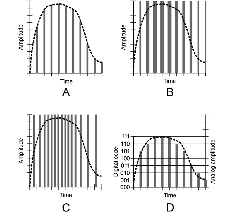
Several types of pulse modulation (PM) are briefly described in the following sections. They are dia-
grammed in Fig. 25-8 as amplitude-versus-time graphs. The modulating waveform in each case is
shown as a dashed curve, and the pulses are shown as vertical gray bars.
414 Wireless Transmitters and Receivers
25-8 Time-domain graphs of various modes of pulse modulation. At A, pulse
amplitude modulation; at B, pulse width modulation; at C, pulse interval
modulation; at D, pulse code modulation.
Pulse Amplitude Modulation
In pulse amplitude modulation (PAM), the strength of each individual pulse varies according to the
modulating waveform. In this respect, PAM resembles AM. An amplitude-versus-time graph of a hy-
pothetical PAM signal is shown in Fig. 25-8A. Normally, the pulse amplitude increases as the instan-
taneous modulating-signal level increases (positive PAM). But this can be reversed, so higher audio
levels cause the pulse amplitude to go down (negative PAM). Then the signal pulses are at their
strongest when there is no modulation. The transmitter works a little harder if negative PAM is used.
Pulse Width Modulation
Another way to change the transmitter output is to vary the width (duration) of the pulses. This is
called pulse width modulation (PWM) or pulse duration modulation (PDM), and is shown in Fig.
25-8B. Normally, the pulse width increases as the instantaneous modulating-signal level increases
(positive PWM). But this can be reversed (negative PWM). The transmitter must work harder to ac-
complish negative PWM. Either way, the peak pulse amplitude remains constant.
Pulse Interval Modulation
Even if all the pulses have the same amplitude and the same duration, modulation can still be accom-
plished by varying how often they occur. In PAM and PWM, the pulses are always sent at the same
time interval, known as the sampling interval. But in pulse interval modulation (PIM), also called pulse
frequency modulation (PFM), pulses can occur more or less frequently than they do when there is no
modulation. A hypothetical PIM signal is shown in Fig. 25-8C. Every pulse has the same amplitude
and the same duration, but the time interval between them changes. When there is no modulation,
the pulses are evenly spaced with respect to time. An increase in the instantaneous data amplitude
might cause pulses to be sent more often, as is the case in Fig. 25-8C ( positive PIM ). Or, an increase
in instantaneous data level might slow down the rate at which the pulses are sent (negative PIM ).
Pulse Code Modulation
In recent years, the transmission of data has been done more and more by digital means. In digital
communications, the modulating data attains only certain defined states, rather than continuously
varying. Digital transmission offers better efficiency than analog transmission. With digital modes,
the signal-to-noise (S/N) ratio is better, the bandwidth is narrower, and there are fewer errors. In
pulse-code modulation (PCM), any of the above aspects—amplitude, duration, or interval—of a
pulse sequence (or pulse train) can be varied. But rather than having infinitely many possible states,
there are finitely many. The number of states is a power of 2, such as 4, 8, or 16. The greater the
number of states, the better the fidelity. An example of 8-level PCM is shown in Fig. 25-8D.
Analog-to-Digital Conversion
Pulse code modulation, such as is shown at Fig. 25-8D, is one form of analog-to-digital (A/D) con-
version. A voice signal, or any continuously variable signal, can be digitized, or converted into a train
of pulses whose amplitudes can achieve only certain defined levels.
Resolution
In A/D conversion, the number of states is always a power of 2, so that it can be represented as a
binary-number code. Fidelity improves as the exponent increases. The number of states is called the
Analog-to-Digital Conversion 415
sampling resolution, or simply the resolution. A resolution of 2
3
= 8 (as shown in Fig. 25-8D) is good
enough for voice transmission, and is the standard for commercial digital voice circuits. A resolu-
tion of 2
4
= 16 is adequate for high-fidelity (hi-fi) music reproduction.
Sampling Rate
The efficiency with which a signal can be digitized depends on the frequency at which sampling is
done. In general, the sampling rate must be at least twice the highest data frequency. For an audio
signal with components as high as 3 kHz, the minimum sampling rate for effective digitization is
6 kHz; the commercial voice standard is 8 kHz. For hi-fi digital transmission, the standard sampling
rate is 44.1 kHz, a little more than twice the frequency of the highest audible sound (approximately
20 kHz).
Image Transmission
Nonmoving images can be sent within the same bandwidth as voice signals. For high-resolution,
moving images, the necessary bandwidth is greater.
Facsimile
Nonmoving images (also called still images) are commonly transmitted by facsimile, also called fax.
If data is sent slowly enough, any amount of detail can be transmitted within a 3-kHz-wide band,
the standard for voice communications. This is why detailed fax images can be sent over a plain old
telephone service (POTS) line.
In an electromechanical fax machine, a paper document or photo is wrapped around a drum.
The drum is rotated at a slow, controlled rate. A spot of light scans from left to right; the drum
moves the document so a single line is scanned with each pass of the light spot. This continues, line
by line, until the complete frame (image) has been scanned. The reflected light is picked up by a
photodetector. Dark parts of the image reflect less light than bright parts, so the current through the
photodetector varies. This current modulates a carrier in one of the modes described earlier, such as
AM, FM, or SSB. Typically, black is sent as a 1.5-kHz audio sine wave, and white as a 2.3-kHz
audio sine wave. Gray shades produce audio sine waves having frequencies between these extremes.
At the receiver, the scanning rate and pattern can be duplicated, and a cathode-ray tube (CRT),
liquid crystal display (LCD), or printer can be used to reproduce the image in grayscale (shades of
gray ranging from black to white, without color).
Slow-Scan Television
One way to think of slow-scan television (SSTV) is to imagine “fast fax.” An SSTV signal, like a fax
signal, is sent within a band of frequencies as narrow as that of a human voice. And, like fax, SSTV
transmission is of still pictures, not moving ones. The big difference between SSTV and fax is that
SSTV images are sent in much less time. The time required to send a complete frame (image or
scene) is 8 seconds, rather than several minutes. This speed bonus comes with a tradeoff: lower res-
olution, meaning less image detail.
Some SSTV signals are received on CRT displays. A computer can be programmed so that its
monitor will act as an SSTV receiver. Converters are also available that allow SSTV signals to be
viewed on a consumer-type TV set.
416 Wireless Transmitters and Receivers
An SSTV frame has 120 lines. The black and white frequencies are the same as for fax transmis-
sion; the darkest parts of the picture are sent at 1.5 kHz and the brightest at 2.3 kHz. Synchroniza-
tion (sync) pulses, that keep the receiving apparatus in step with the transmitter, are sent at 1.2 kHz.
A vertical sync pulse tells the receiver that it’s time to begin a new frame; it lasts for 30 milliseconds
(ms). A horizontal sync pulse tells the receiver that it’s time to start a new line in a frame; its duration
is 5 ms. These pulses prevent rolling (haphazard vertical image motion) or tearing (lack of horizon-
tal synchronization).
Fast-Scan Television
Conventional television is also known as fast-scan TV (FSTV). The frames are transmitted at the rate
of 30 per second. There are 525 lines per frame. The quick frame time, and the increased resolution,
of FSTV make it necessary to use a much wider frequency band than is the case with fax or SSTV.
A typical video FSTV signal takes up 6 MHz of spectrum space, or 2000 times the bandwidth of a
fax or SSTV signal.
Fast-scan TV is almost always sent using conventional AM. Wideband FM can also be used.
With AM, one of the sidebands can be filtered out, leaving just the carrier and the other sideband.
This mode is called vestigial sideband (VSB) transmission. It cuts the bandwidth of an FSTV signal
down to about 3 MHz.
Because of the large amount of spectrum space needed to send FSTV, this mode isn’t practical
at frequencies below about 30 MHz. All commercial FSTV transmission is done above 50 MHz,
with the great majority of channels having frequencies far higher than this. Channels 2 through 13
on your TV receiver are sometimes called the very high frequency (VHF) channels; the higher chan-
nels are called the ultrahigh frequency (UHF) channels.
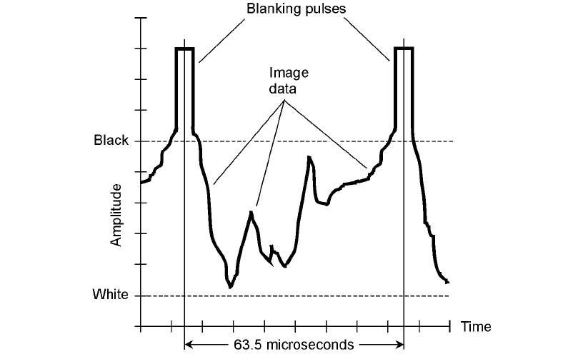
Figure 25-9 is a time-domain graph of the waveform of a single line in an FSTV video signal.
This represents
1
⁄525 of a complete frame. The highest instantaneous signal amplitude corresponds
to the blackest shade, and the lowest amplitude to the lightest shade. Thus, the FSTV signal is sent
negatively. The reason that FSTV signals are sent this way is that retracing (moving from the end of
one line to the beginning of the next) must be synchronized between the transmitter and receiver.
This is guaranteed by a defined, strong blanking pulse. This pulse tells the receiver when to retrace;
it also shuts off the beam while the receiver display is retracing. Have you noticed that weak TV sig-
nals have poor contrast? (You have, if you’re old enough to remember “rabbit ears”!) Weakened
blanking pulses result in incomplete retrace blanking. But this is better than having the TV receiver
completely lose track of when it should retrace.
Color FSTV works by sending three separate monochromatic signals, corresponding to the pri-
mary colors red, blue, and green. The signals are literally black-and-red, black-and-blue, and black-
and-green. These are recombined at the receiver and displayed on the screen as a fine, interwoven
matrix of red, blue, and green dots. When viewed from a distance, the dots are too small to be indi-
vidually discernible. Various combinations of red, blue, and green intensities result in reproduction
of all possible hues and saturations of color.
High-Definition Television
The term high-definition television (HDTV) refers to any of several similar methods for getting more
detail into a TV picture, and for obtaining better audio quality, compared with standard FSTV.
A standard FSTV picture has 525 lines per frame, but HDTV systems have between 787 and
1125 lines per frame. The image is scanned about 60 times per second. High-definition TV is often
Image Transmission 417
sent in a digital mode; this offers another advantage over conventional FSTV. Digital signals prop-
agate better, are easier to deal with when they are weak, and can be processed in ways that analog
signals cannot.
Some HDTV systems use interlacing in which two rasters are meshed together. This effectively
doubles the image resolution without doubling the cost of the hardware. But it can cause annoying
jitter in fast-moving or fast-changing images.
Digital Satellite TV
Until the early 1990s, a satellite television installation required a dish antenna several feet in diam-
eter. A few such systems are still in use. The antennas are expensive, they attract attention (some-
times unwanted), and they are subject to damage from ice storms, heavy snows, and high winds.
Digitization has changed this situation. In any communications system, digitization allows the use
of smaller receiving antennas, smaller transmitting antennas, and/or lower transmitter power levels.
Engineers have managed to get the diameter of the receiving dish down to about 2 ft.
A pioneer in digital TV was RCA (Radio Corporation of America), which developed the Digi-
tal Satellite System (DSS). The analog signal is changed into digital pulses at the transmitting station
via A/D conversion. The digital signal is amplified and sent up to a geostationary satellite. The satel-
lite has a transponder that receives the signal, converts it to a different frequency, and retransmits it
back toward the earth. The return signal is picked up by a portable dish. A tuner selects the channel.
Digital signal processing (DSP) can be used to improve the quality of reception under marginal con-
ditions. The digital signal is changed back into analog form, suitable for viewing on a conventional
FSTV set, by means of digital-to-analog (D/A) conversion.
418 Wireless Transmitters and Receivers
25-9 Time-domain graph of a single line in an FSTV video frame.
The Electromagnetic Field
In a radio or television transmitting antenna, electrons are moving back and forth at an extreme
speed. Their velocity is constantly changing as they speed up in one direction, slow down, reverse
direction, speed up again, and so on. Any change of velocity (that is, of speed and/or direction) con-
stitutes acceleration.
How It Happens
When electrons move, a magnetic (M) field is produced. When electrons accelerate, a changing
magnetic field is produced. An alternating M field gives rise to an alternating electric (E) field, and
this generates another alternating M field. This process repeats over and over, endlessly, and the ef-
fect propagates (travels) through space at the speed of light. The E and M fields expand alternately
outward from the source in spherical wavefronts. At any given point in space, the E flux is perpen-
dicular to the M flux. The direction of wave travel is perpendicular to both the E and M flux lines.
This is an electromagnetic (EM) field.
An EM field can have any conceivable frequency, ranging from many years per cycle to
quadrillions of cycles per second. The sun has a magnetic field that oscillates with a 22-year cycle.
Radio waves oscillate at thousands, millions, or billions of cycles per second. Infrared (IR), visible
light, ultraviolet (UV), X rays, and gamma rays are EM fields that alternate at many trillions (mil-
lion millions) of cycles per second.
Frequency versus Wavelength
All EM fields have two important properties: the frequency and the wavelength. These are inversely re-
lated. You’ve already learned about frequency. Wavelength, for an EM field, is a rather sophisticated
concept. It is measured between any two adjacent points on the wave at which the E and M fields
have exactly the same amplitudes, and occur in exactly the same relative directions. The following
equations relate the frequency and the wavelength of an EM field in free space (the air or a vacuum).
Let f
MHz
be the frequency of an EM wave in megahertz, and L
ft
be the wavelength in feet. Then
the two are related as follows:
L
ft
= 984 / f
MHz
If the wavelength is given as L
m
in meters, then
L
m
= 300 / f
MHz
The inverses of these formulas, for finding the frequency if the wavelength is known, are
f
MHz
= 984 / L
ft
f
MHz
= 300 / L
m
Velocity Factor
In media other than free space, the speed at which EM fields propagate is slower than the speed of light.
As a result, wavelength is shortened by a factor known as the velocity factor, symbolized v. The value of v
can be anything between 0 (representing zero speed of propagation) and 1 (representing the speed of
propagation in free space, which is approximately 186,000 mi/s or 300,000 km/s).The velocity factor can
also be expressed as a percentage v
%
. In that case, the smallest possible value is 0 percent, and the largest is
100 percent. The velocity factor in practical situations is rarely less than about 0.60, or 60 percent.
The Electromagnetic Field 419
Velocity factor is important in the design of RF transmission lines and antenna systems, when
sections of cable, wire, or metal tubing must be cut to specific lengths measured in wavelengths or
fractions of a wavelength. Taking the velocity factor v, expressed as a ratio, into account, the preced-
ing four formulas become:
L
ft
= 984v / f
MHz
L
m
= 300v / f
MHz
f
MHz
= 984v / L
ft
f
MHz
= 300v / L
m
The Electromagnetic Spectrum
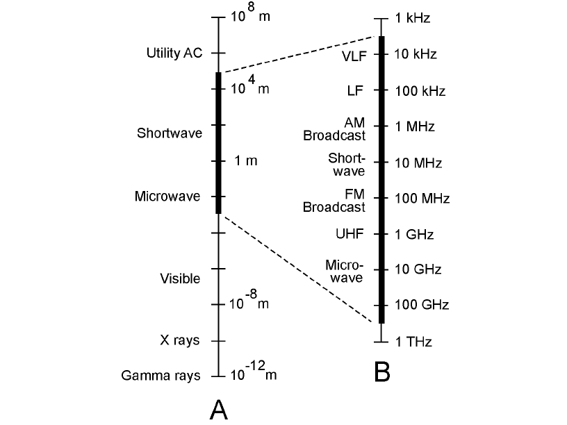
The entire range of EM wavelengths is called the electromagnetic (EM) spectrum. Scientists use log-
arithmic scales to depict the EM spectrum, as shown in Fig. 25-10. The RF spectrum, which includes
radio, television, and microwaves, is blown up in this illustration, and is labeled for frequency.
420 Wireless Transmitters and Receivers
25-10 At A, the EM spectrum from 10
8
m to 10
−12
m,
with each vertical division representing two orders
of magnitude (an increase or decrease of the
wavelength by a factor of 100). At B, the RF
spectrum, with each vertical division representing
one order of magnitude (an increase or decrease of
the frequency by a factor of 10).
