Gibilisco S. Teach Yourself Electricity and Electronics
Подождите немного. Документ загружается.

Wave Propagation
Radio-wave propagation has been a fascinating science ever since Marconi and Tesla discovered,
around the year 1900, that EM fields can travel over long distances without any supporting infra-
structure whatsoever. Let’s look at a few of the factors that affect wireless communications at radio
frequencies.
Polarization
The orientation of the E field lines of flux is defined as the polarization of an EM wave. If the E field
flux lines are parallel to the earth’s surface, you have horizontal polarization. If the E field flux lines are
perpendicular to the surface, you have vertical polarization. Polarization can also be slanted, of course.
In some situations, the E flux lines rotate as the wave travels through space. This is circular polar-
ization if the E field intensity remains constant. If the E field intensity is more intense in some planes
than in others, the polarization is elliptical. Rotating polarization can be clockwise or counterclockwise,
viewed as the wavefronts approach. The rotational direction is called the sense of polarization.
The Line-of-Sight Wave
Electromagnetic waves follow straight lines unless something makes them bend. Line-of-sight prop-
agation can take place even when the receiving antenna cannot be seen from the transmitting an-
tenna. To some extent, radio waves penetrate nonconducting objects such as trees and frame houses.
The line-of-sight wave consists of two components: the direct wave and the reflected wave.
The direct wave: The longest wavelengths are least affected by obstructions. At very low, low,
and medium frequencies, direct waves can diffract around things. As the frequency rises, especially
above about 3 MHz, obstructions have a greater and greater blocking effect.
The reflected wave: Electromagnetic waves reflect from the earth’s surface and from conducting ob-
jects like wires and steel beams. The reflected wave always travels farther than the direct wave. The two
waves are usually not in phase at the receiving antenna. If they’re equally strong but 180° out of phase,
a dead spot occurs. This phenomenon is most noticeable at the highest frequencies. At VHF and UHF,
an improvement in reception can sometimes result from moving the transmitting or receiving antenna
just a few inches. In mobile operation, when the transmitter and/or receiver are moving, dead spots
produce rapid, repeated interruptions in the received signal. This is called picket fencing.
The Surface Wave
At frequencies below about 10 MHz, the earth’s surface conducts ac quite well. Because of this, ver-
tically polarized EM waves follow the surface for hundreds or even thousands of miles, with the earth
actually helping to transmit the signals. The lower the frequency, the lower the ground loss, and the
farther the waves can travel by surface-wave propagation. Horizontally polarized waves do not travel
well in this mode, because horizontal E field flux is shorted out by the earth. Above about 10 MHz,
the earth becomes lossy, and surface-wave propagation is not useful for more than a few miles.
Sky-Wave EM Propagation
Ionization in the upper atmosphere, caused by solar radiation, can return EM waves to the earth at
certain frequencies. The ionization takes place at three or four distinct layers.
The lowest ionized region is called the D layer. It exists at an altitude of about 30 mi (50 km),
and is ordinarily present only on the daylight side of the planet. This layer absorbs radio waves at
some frequencies, impeding long-distance ionospheric propagation.
Wave Propagation 421
The E layer, about 50 mi (80 km) above the surface, also exists mainly during the day, although
nighttime ionization is sometimes observed. The E layer can provide medium-range radio commu-
nication at certain frequencies.
The uppermost layers are called the F
1
layer and the F
2
layer. The F
1
layer, normally present only
on the daylight side of the earth, forms at about 125 mi (200 km) altitude; the F
2
layer exists at
about 180 mi (300 km) over most, or all, of the earth. Sometimes the distinction between the F
1
and F
2
layers is ignored, and they are spoken of together as the F layer. Communication by means
of F-layer propagation can usually be accomplished between any two points on the earth at some
frequencies between 5 MHz and 30 MHz.
Tropospheric Propagation
At frequencies above about 30 MHz, the lower atmosphere bends radio waves toward the surface.
Tropospheric banding occurs because the index of refraction of air, with respect to EM waves, de-
creases with altitude. The effect is similar to the way sound waves sometimes travel long distances
over the surface of a calm lake in the early morning or early evening, letting you hear a conversation
more than a mile away. Tropospheric propagation makes it possible to communicate for hundreds
of miles when the ionosphere will not return waves to the earth.
Another type of tropospheric propagation is called ducting. It takes place when EM waves are
trapped in a layer of cool, dense air sandwiched between two layers of warmer air. Like bending,
ducting occurs almost entirely at frequencies above 30 MHz.
Still another tropospheric-propagation mode is known as troposcatter. This takes place because
air molecules, dust grains, and water droplets scatter some of the EM field. This effect is commonly
seen at VHF and UHF.
Tropospheric propagation in general, without mention of the specific mode, is sometimes
called tropo.
Auroral Propagation
In the presence of unusual solar activity, the aurora (northern lights or southern lights) can return
radio waves to the earth. This is known as auroral propagation. The aurora occur at altitudes of about
40 to 250 mi (65 to 400 km). Theoretically, auroral propagation is possible, when the aurora are ac-
tive, between any two points on the surface from which the same part of the aurora lie on a line of
sight. Auroral propagation seldom occurs when one end of the circuit is at a latitude less than 35°
north or south of the equator.
Auroral propagation is characterized by rapid and deep fading. This almost always renders ana-
log voice and video signals unintelligible. Digital modes are most effective for communication via
auroral propagation, but the carrier is often spread out over several hundred hertz as a result of phase
modulation induced by auroral motion. This severely limits the maximum data transfer rate. Auro-
ral propagation is often accompanied by deterioration in ionospheric propagation.
Meteor Scatter
Meteors produce ionized trails that persist for approximately 0.5 s up to several seconds, depending
on the size of a particular meteor, its speed, and the angle at which it enters the atmosphere. This is
not enough time for the transmission of much data, but during a meteor shower, multiple trails can
result in almost continuous ionization for a period of hours. Such ionized regions reflect radio waves
at certain frequencies. This is meteor scatter propagation. It can take place at frequencies considerably
422 Wireless Transmitters and Receivers
above 30 MHz, and occurs over distances ranging from just beyond the horizon up to about 1500
mi (2400 km), depending on the altitude of the ionized trail and the relative positions of the trail,
the transmitting station, and the receiving station.
Moonbounce
The moon, like the earth, reflects EM fields. This makes it possible to communicate by means of
earth-moon-earth (EME), also called moonbounce. High-powered transmitters, sophisticated an-
tenna systems, and sensitive receivers are needed for EME. Some moonbounce communication is
done by radio amateurs at frequencies from 50 MHz to over 2 GHz.
Transmission Media
Data can be transmitted over various media. The most common are cable, radio (also called wireless),
satellite links (a specialized form of wireless), and fiber optics. Cable, radio/TV, and satellite commu-
nications use the RF spectrum. Fiber optics uses IR or visible light energy.
Cable
The earliest cables were simple wires that carried dc. Nowadays, data transmission cables more often
carry ac at radio frequencies. One advantage of using RF is the fact that the signals can be amplified
at intervals on a long span. This greatly increases the distances over which data can be sent by cable.
Another advantage of using RF is the fact that numerous signals can be carried over a single cable,
with each signal on a different frequency.
Cables can consist of pairs of wires, somewhat akin to lamp cords. But more often coaxial cable,
of the type described and illustrated at the end of Chap. 10, is used. This has a center conductor sur-
rounded by a cylindrical shield. The shield is grounded, and the center conductor carries the signals.
The shield keeps signals confined to the cable, and also keeps external EM fields from interfering
with the signals.
Radio
All radio and TV signals are electromagnetic waves. The radio or TV transmitter output is coupled
into an antenna system located at some distance from the transmitter. The energy follows a transmis-
sion line, also called a feed line, from the transmitter output to the antenna itself.
Most radio antenna transmission lines are coaxial cables. There are other types, used in special
applications. At microwaves, hollow tubes called waveguides are used to transfer the energy from a
transmitter to the antenna. A waveguide is more efficient than coaxial cable at the shortest radio
wavelengths. Radio amateurs sometimes use parallel-wire transmission lines, resembling the ribbon
cable popular for use with consumer TV receiving antennas. In a parallel-wire line, the RF currents
in the two conductors are always 180° out of phase, so that their EM fields cancel each other. This
keeps the transmission line from radiating, guiding the EM field along toward the antenna. The en-
ergy is radiated when it reaches the antenna.
The RF bands are generally categorized from very low frequency (VLF) through extremely high
frequency (EHF), according to the breakdown in Table 25-1. As noted in Chap. 24, the exact lower
limit of the VLF range is a matter of disagreement in the literature. In Table 25-1, it is defined as
3 kHz, which is consistent with defining the frequency boundaries between RF bands by order of
magnitude.
Transmission Media 423

Satellite Systems
At very high frequencies (VHF) and above, many communications circuits use satellites in geosta-
tionary orbits around the earth. If a satellite is directly over the equator at an altitude of 22,300 mi
(36,000 km) and orbits from west to east, it follows the earth’s rotation, thereby staying in the same
spot in the sky as seen from the surface, and is thus a geostationary satellite.
A single geostationary satellite is on a line of sight with about 40 percent of the earth’s surface.
Three such satellites, placed at 120° (
1
⁄3 circle) intervals around the planet, allow coverage of all
populated regions. A dish antenna can be aimed at a geostationary satellite, and once the antenna is
in place, it need not be turned or adjusted.
Another form of satellite system uses multiple satellites in low orbits that take them over the
earth’s poles. These satellites are in continuous, rapid motion with respect to the surface. But if there
are enough of them, they can act like repeaters in a cell phone network, and maintain reliable com-
munications between any two points on the surface at all times. Directional antennas are not nec-
essary in these systems, which are called low earth orbit (LEO) satellite networks.
Fiber Optics
Beams of IR or visible light can be modulated, just as can RF carriers. The frequency of an IR or vis-
ible light beam is higher than the frequency of any RF signal, allowing modulation by data at rates
higher than anything possible with radio.
Fiber-optic technology offers several advantages over wire cables (which are sometimes called
copper because the conductors are usually made of that metallic element). A fiber-optic cable is
cheap. It is light in weight. It is immune to interference from outside EM fields. A fiber-optic cable
does not corrode as metallic wires do. Fiber-optic cables are inexpensive to maintain and easy to re-
pair. An optical fiber can carry far more signals than a cable, because the frequency bands are far
wider in terms of megahertz or gigahertz.
The whole RF spectrum, from VLF through EHF, can (at least in theory) be imprinted on a
single beam of light and sent through an optical fiber no thicker than a strand of hair!
Two Basic Receiver Designs
A wireless or radio receiver converts EM waves into the original messages sent by a distant transmit-
ter. Let’s begin our study of receivers by defining a few of the most important criteria for operation,
and then we’ll look at two common designs.
424 Wireless Transmitters and Receivers
Table 25-1. Bands in the RF spectrum.
Frequency designation Frequency range Wavelength range
Very Low (VLF) 3 kHz–30 kHz 100 km–10 km
Low (LF) 30 kHz–300 kHz 10 km–1 km
Medium (MF) 300 kHz–3 MHz 1 km–100 m
High (HF) 3 MHz–30 MHz 100 m–10 m
Very High (VHF) 30 MHz–300 MHz 10 m–1 m
Ultra High (UHF) 300 MHz–3 GHz 1 m–100 mm
Super High (SHF) 3 GHz–30 GHz 100 mm–10 mm
Extremely High (EHF) 30 GHz–300 GHz 10 mm–1 mm
Specifications
The specifications of a receiver indicate how well it can do the functions it is designed to perform.
Sensitivity: The most common way to express receiver sensitivity is to state the number of mi-
crovolts that must exist at the antenna terminals to produce a certain signal-to-noise (S/N) ratio or
signal-plus-noise-to-noise (S+N/N) ratio in decibels (dB). Sensitivity is related to the gain of the front
end (the amplifier or amplifiers connected to the antenna), but the amount of noise this stage gen-
erates is more significant, because subsequent stages amplify the front-end noise output as well as
the signal output.
Selectivity: The passband, or bandwidth that the receiver can hear, is established by a wideband
preselector in the early RF amplification stages, and is honed to precision by narrowband filters in
later amplifier stages. The preselector makes the receiver optimally sensitive within a range of ap-
proximately plus-or-minus 10 percent (⫾10%) of the desired signal frequency. The narrowband fil-
ter responds only to the frequency or channel of a specific signal to be received; signals in nearby
channels are rejected.
Dynamic range: The signals at a receiver input vary over several orders of magnitude (multi-
ples or powers of 10) in terms of absolute voltage. Dynamic range is the ability of a receiver to
maintain a fairly constant output, and yet to maintain its rated sensitivity, in the presence of sig-
nals ranging from very weak to very strong. The dynamic range in a good receiver is in excess
of 100 dB.
Noise figure: The less internal noise a receiver produces, in general, the better is the S/N ratio.
Excellent S/N ratio in the presence of weak signals is only possible when the noise figure, a measure
of internally generated receiver noise, is low. This is paramount at VHF, UHF, and microwave fre-
quencies. Gallium-arsenide field effect transistors (GaAsFETs) are well known for the low levels of
noise they generate, even at quite high frequencies. Other types of FETs can be used at lower fre-
quencies. Bipolar transistors tend to be rather noisy.
Direct-Conversion Receiver
A direct-conversion receiver derives its output by mixing incoming signals with the output of a tun-
able (that is, variable frequency) local oscillator (LO). The received signal is fed into a mixer, along
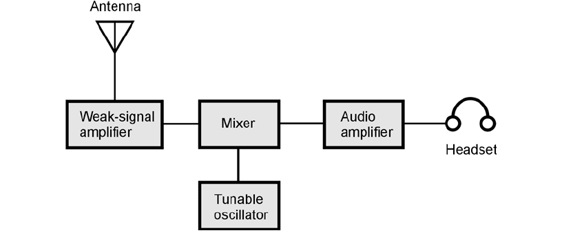
with the output of the LO. Figure 25-11 is a block diagram of a direct-conversion receiver.
For the reception of on/off keyed Morse code, also called radiotelegraphy or continuous wave
(CW), the LO, also called a beat-frequency oscillator (BFO), is set a few hundred hertz above or
below the signal frequency. This can also be done in order to receive FSK signals. The audio output
has a frequency equal to the difference between the LO and incoming carrier frequencies. For recep-
tion of AM or SSB signals, the LO is set to precisely the same frequency as that of the signal carrier.
This condition is known as zero beat because the beat frequency, or difference frequency, between the
LO and the signal carrier is equal to zero.
A direct-conversion receiver provides rather poor selectivity. That means it can’t separate incom-
ing signals very well when they are close together in frequency. This is because signals on either side
of the LO frequency can be heard at the same time. A selective filter can theoretically eliminate this.
Such a filter must be designed for a fixed frequency if it is to work well. But in a direct-conversion
receiver, the RF amplifier works over a wide range of frequencies.
Superheterodyne Receiver
A superheterodyne receiver, also called a superhet, uses one or more local oscillators and mixers to ob-
tain a constant-frequency signal. A fixed-frequency signal is more easily processed than a signal that
Two Basic Receiver Designs 425
changes in frequency. The incoming signal is first passed through a tunable, sensitive front end. The
output of the front end is mixed with the signal from a tunable, unmodulated LO. Either the sum
or the difference signal is amplified. This is the first intermediate frequency (IF), which can be filtered
to obtain a high degree of selectivity.
If the first IF signal is detected, the radio is a single-conversion receiver. Some receivers use a sec-
ond mixer and second LO, converting the first IF to a lower-frequency second IF. This is a double-
conversion receiver. The IF bandpass filter can be constructed for use on a fixed frequency, allowing
superior selectivity and facilitating adjustable bandwidth. The sensitivity is enhanced because fixed
IF amplifiers are easy to keep in tune.
A superheterodyne receiver can intercept or generate unwanted signals. False signals external to
the receiver are called images; internally generated signals are called birdies. If the LO frequencies are
carefully chosen, images and birdies do not cause problems during ordinary operation of the
receiver.
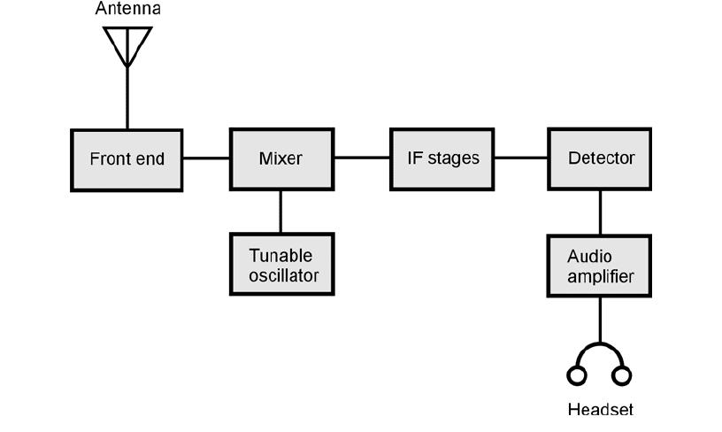
Figure 25-12 is a block diagram of a generic single-conversion superheterodyne receiver. (Indi-
vidual receiver designs vary somewhat.) Here’s what each stage does.
Front end: The front end consists of the first RF amplifier, and often includes LC bandpass fil-
ters between the amplifier and the antenna. The dynamic range and sensitivity of a receiver are de-
termined by the performance of the front end.
Mixer: A mixer stage converts the variable signal frequency to a constant IF. The output is ei-
ther the sum or the difference of the signal frequency and the tunable LO frequency.
IF stages: The IF stages are where most of the gain takes place. These stages are also where opti-
mum selectivity is obtained.
Detector: The detector extracts the information from the signal. Common circuits are the enve-
lope detector for AM, the product detector for SSB, FSK, and CW, and the ratio detector for FM.
Audio amplifier: Following the detector, one or two stages of audio amplification are employed
to boost the signal to a level suitable for a speaker or headset. Alternatively, the signal can be fed to
a printer, facsimile machine, or computer.
426 Wireless Transmitters and Receivers
25-11 Block diagram of a direct-conversion receiver.
Predetector Stages
In a superhet, the stages preceding the first mixer must be designed so they provide reasonable gain,
but produce as little noise as possible. They must also be capable of handling strong signals without
desensitization (losing gain), also known as overloading.
Preamplifier
All preamplifiers operate in class A, and most employ FETs. An FET has a high input impedance
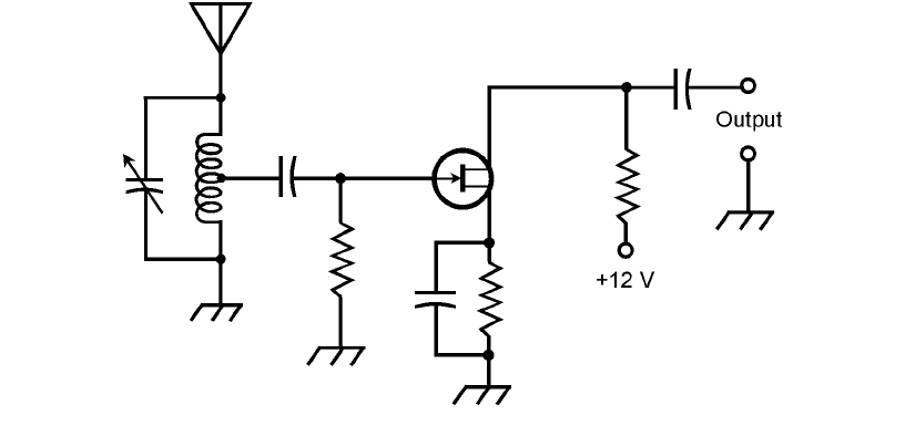
that is ideally suited to weak-signal work. Figure 25-13 shows a simple RF preamplifier circuit.
Input tuning reduces noise and provides some selectivity. This circuit produces 5 dB to 10 dB gain,
depending on the frequency and the choice of FET.
It is important that the preamplifier be linear, and that it remain linear in the presence of strong
input signals. Nonlinearity results in unwanted mixing in RF amplifiers. The mixing products pro-
duce intermodulation distortion (IMD), or intermod. That can wreak havoc in a receiver, producing
numerous false signals. It also degrades the S/N ratio by generating hash, the result of complex mix-
ing of many false signals over a wide range of frequencies.
The Front End
At low and medium frequencies, there is considerable atmospheric noise, and the design of a front-
end circuit is simple. Above 30 MHz, atmospheric noise diminishes, and the main factor that lim-
its the sensitivity is noise generated within the receiver. For this reason, front-end design becomes
increasingly critical as the frequency rises through the VHF, UHF, and microwave spectra.
Predetector Stages 427
25-12 Block diagram of a single-conversion superheterodyne receiver.
The front end, like a preamplifier, must be as linear as possible; the greater the degree of non-
linearity, the more susceptible the circuit is to the generation of mixing products. The front end
should also have the greatest possible dynamic range.
Preselector
The preselector provides a bandpass response that improves the S/N ratio, and reduces the likeli-
hood of receiver overloading by a strong signal far removed from the operating frequency. The pre-
selector provides image rejection in a superheterodyne circuit. Most preselectors have a 3-dB
bandwidth that is a few percent of the received frequency.
A preselector can be tuned by means of tracking with the tuning dial, but this requires careful
design and alignment. Some receivers incorporate preselectors that must be adjusted independently
of the receiver tuning.
IF Chain
A high IF (several megahertz) is preferable to a low IF (less than 1 MHz) for image rejection. But a
low IF is better for obtaining good selectivity. Double-conversion receivers have a comparatively
high first IF and a low second IF to get the best of both worlds.
Intermediate-frequency amplifiers can be cascaded with tuned-transformer coupling. The am-
plifiers follow the mixer and precede the detector. Double-conversion receivers have two chains of
IF amplifiers. The first IF chain follows the first mixer and precedes the second mixer, and the sec-
ond IF chain follows the second mixer and precedes the detector.
The selectivity of the IF chain in a superheterodyne receiver can be expressed mathematically.
The bandwidths are compared for two power-attenuation values, usually 3 dB and 30 dB. This gives
an indication of the shape of the bandpass response. The ratio of the 30-dB selectivity to the 3-dB
selectivity is called the shape factor. A rectangular response is desirable in most applications. The
smaller the shape factor, the more rectangular the response.
428 Wireless Transmitters and Receivers
25-13 A tunable FET preamplifier for use in a radio receiver.
Detectors
Detection, also called demodulation, is the recovery of information such as audio, images, or printed
data from a signal.
Detection of AM
The modulating waveform can be extracted from an AM signal by rectifying the carrier wave. A
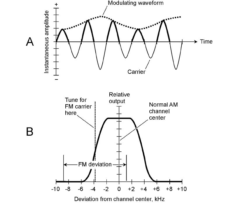
simplified time-domain view of this is shown in Fig. 25-14A. The rapid pulsations occur at the car-
Detectors 429
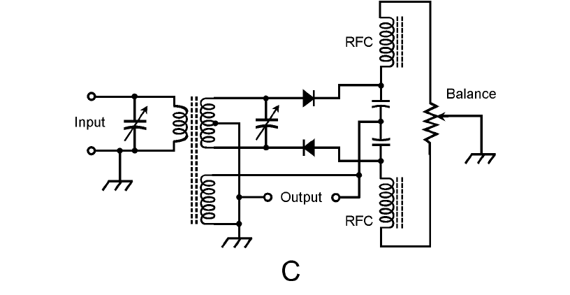
25-14 At A, envelope detection of AM, shown in the time domain. At B, slope
detection of FM, shown in the frequency domain.
rier frequency; the slower fluctuation is a duplication of the modulating data. The carrier pulsations
are smoothed out by passing the output through a capacitor large enough to hold the charge for one
carrier current cycle, but not so large that it smoothes out the cycles of the modulating signal. This
scheme is known as envelope detection.
Detection of CW
For detection of CW signals, it is necessary to inject a signal into the receiver a few hundred hertz
from the carrier. The injected signal is produced by a tunable beat-frequency oscillator (BFO). The
BFO signal and the desired CW signal are mixed, or heterodyned, to produce audio output at the
difference frequency. The BFO is tuned to a frequency that results in a comfortable listening pitch,
usually 500 to 1000 Hz. This is called heterodyne detection.
Detection of FSK
The detection of FSK signals can be done using the same method as CW detection. The carrier
beats against the BFO in the mixer, producing an audio tone that alternates between two different
pitches.
With FSK, the BFO frequency is set a few hundred hertz above or below both of the carrier fre-
quencies—that is, of both the mark frequency and the space frequency. The frequency offset, or differ-
ence between the BFO and signal frequencies, determines the audio output frequencies, and must
430 Wireless Transmitters and Receivers
25-14 At C, a ratio detector circuit for demodulating FM signals.
