George W. Stimson introduction to Airborne Radar (Se)
Подождите немного. Документ загружается.

CHAPTER 31 Principles of Synthetic Array Aperture Radar
417
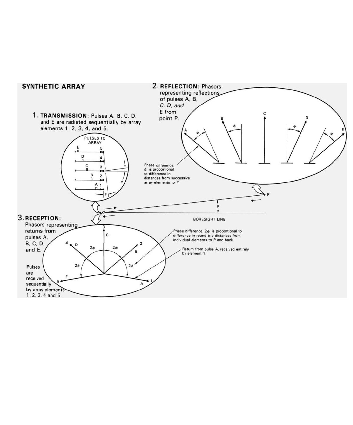
Synthetic Array. In the case of a synthetic array, transmission
bmthe individual array elements is sequential. The first pulse is
transmitted and received entirely by the first element; the second
pulse, entirely by the second element; and so on. Consequently,
the returns received by successive elements differ in phase by
amounts proportional to the differences in the
round-trip
distance
from each element to P and back to the element again.
Thus, for any one angle off the boresight line, the progressive
shift in the phases of the returns received by successive array
elements is twice as great for a synthetic array as for a real array
(The doubling of phase shift gives the beam of the synthetic
array its sin 2x/2x shape.)
Significance. Because of the doubling of phase shifts, the null-to-
null beamwidth of a synthetic array is only half the null-to-null
beamwidth of a real array of the same length. And the 3-dB
beamwidth is roughly 70 percent of the two-way 3-dB beamwidth
of the real array. (At the ⫺3 dB points, sin (2x/ 2x) ≅ 0.7 (sin x/x)
2
.)
The doubling of the phase shifts must, of course, also be kept
in mind when calculating such factors as the phase corrections
necessary to focus an array and the angles at which grating lobes
(see Chapter 32) will occur.
PART VII High Resolution Ground Mapping and Imaging
418
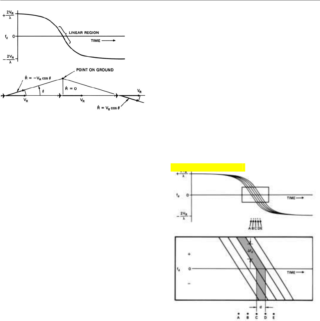
Doppler Frequency Versus Azimuth Angle. Figure 19
shows the doppler history of the return from a point of
ground offset from the radar’s flight path. When the point is
a great distance ahead, its doppler frequency corresponds
very nearly to the full speed of the radar and is positive.
When the point is a great distance behind, its doppler fre-
quency similarly corresponds to the full speed of the radar,
but is negative.
As the radar goes by the point, its doppler frequency
decreases at virtually a constant rate, passing through zero
when the point is at an angle of 90˚ to the radar’s velocity. If
the radar antenna has a reasonably narrow beam and is
looking out to the side at a reasonably large azimuth angle,
the point will be in the antenna beam only during this lin-
early decreasing portion of the point’s doppler history.
A plot of this portion of the doppler histories of several
evenly spaced points at the same offset range is shown in
Fig. 20.
19. As a radar passes a point on the ground, its doppler frequen-
cy decreases at a nearly linear rate, passing through zero
when the point is at an angle of 90
˚ to the radar‘s velocity.
20. Doppler histories of evenly spaced points on the ground. The
instantaneous frequency difference, ∆f
d
, is proportional to the
azimuthal distance between points, d.
As you can see, the histories are identical—the frequency
decreases at the same constant rate—except for being stag-
gered slightly in time. Because of this stagger, at any one
instant, the return from every point has a slightly different
frequency. The difference between the frequencies for adja-
cent points corresponds to the azimuth separation of the
points. We can isolate the return received from each point,
therefore, by virtue of this difference in doppler frequency.
Click for high-quality image
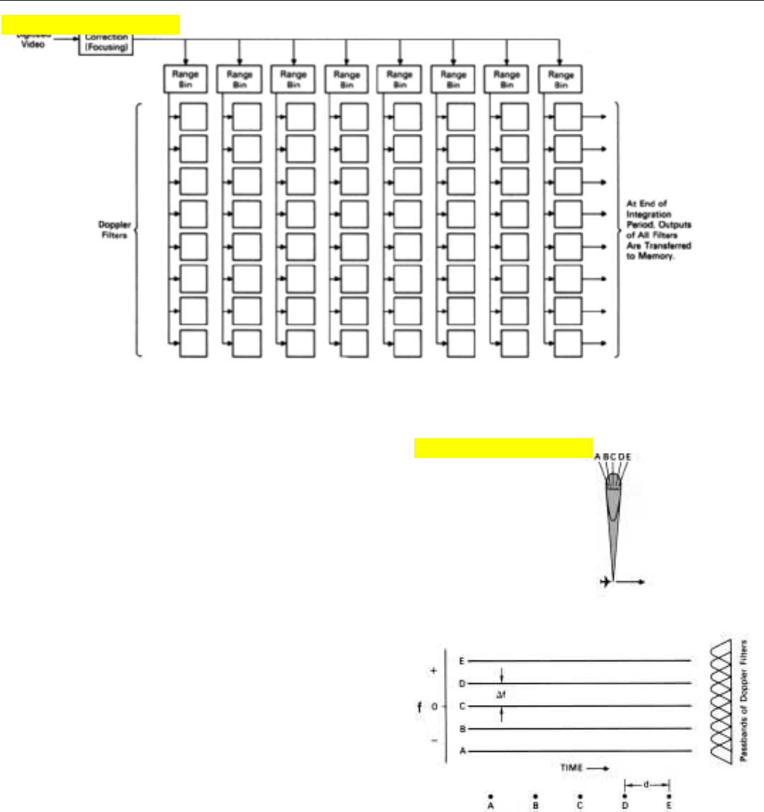
Implementation. The block diagram of Fig. 21 (above)
indicates in general how doppler processing is done.
At the outset, a phase correction is made to the returns
received from each pulse to remove the linear slope of the
doppler histories (i.e., to focus the array). This process,
called focusing, converts the return from each point on the
ground to a constant doppler frequency (Fig. 22). That fre-
quency corresponds to the azimuth angle of the point, as
seen from the center of the segment of the flight path over
which the return was received.
Every time the aircraft traverses a distance equal to the
length of the array that is to be synthesized, the phase-cor-
rected returns which accumulate in each range bin are
applied to a separate bank of doppler filters. Thus, for every
array length, as many banks of filters are formed as there
are range bins. The integration time for the filters is the
length of time the aircraft takes to fly the array length. The
number of filters included in each bank correspondingly
depends upon the length of the array. The greater it is (hence
the longer the filter integration time), the narrower the filter
passbands and the greater the number of filters required to
span a given band of doppler frequencies. The narrower the
filters, of course, the finer the azimuth resolution.
Since the frequencies to be filtered are relatively constant
over the integration time and (for uniformly spaced points
on the ground) are evenly spaced, the fast Fourier trans-
form (FFT) can be used to form the filters, greatly reducing
the amount of computation. Herein lies the advantage of
doppler processing.
CHAPTER 31 Principles of Synthetic Array Aperture Radar
419
21. How doppler processing is done. After focusing corrections have been made, returns are sorted by range. When returns from a complete
array have been received, a separate bank of filters is formed for each range bin.
22. A phase correction converts the return from each point on the
ground to a constant frequency, enabling the doppler filters to
be formed with the FFT.
Click for high-quality image
Click for high-quality image
PART VII High Resolution Ground Mapping and Imaging
420
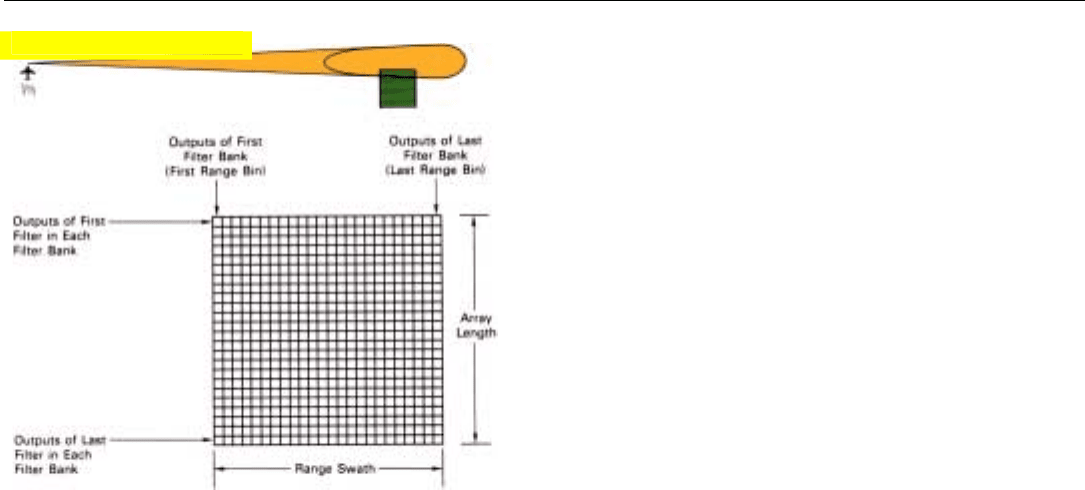
As required for the FFT, the filters are formed at the end
of the integration period, i.e., after the radar has traversed
an entire array length. The outputs of each bank of filters
represent the returns from a single column of resolution
cells at the same range—the range of the range bin for
which the bank was formed (Fig. 23). The outputs of all of
the filter banks, therefore, can be transferred as a block, in
parallel, directly to the appropriate positions in the display
memory. The radar, meanwhile, has traversed another array
length thereby accumulating the data needed to form the
next set of filter banks, and the process is repeated.
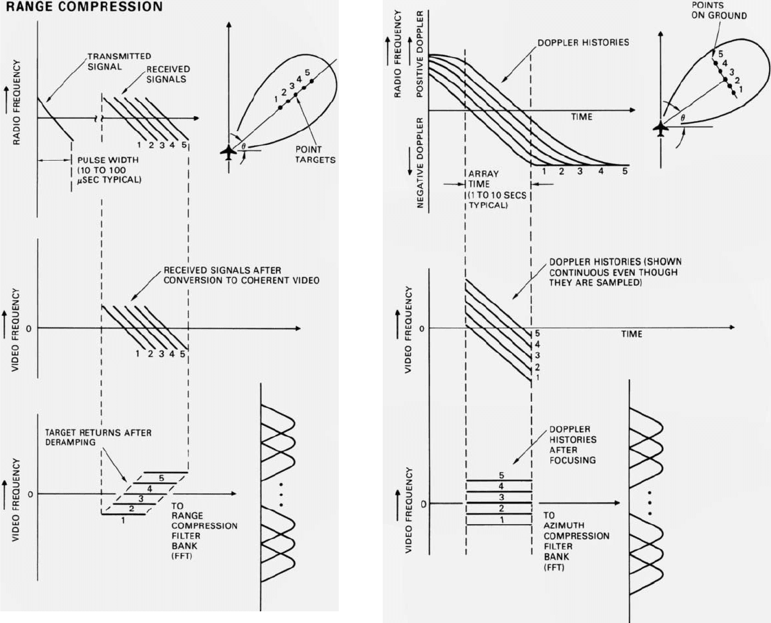
Incidentally, as illustrated in the panel on the facing page,
the focusing and azimuth compression process just
described is strikingly similar to the stretch-radar deramping
and range compression process for decoding chirp pulses.
Reduction in Arithmetic Operations Achieved. Having
gained (hopefully) a clear picture of the doppler-filtering
method of azimuth compression, let’s see what kind of sav-
ing in arithmetic operations it actually provides. To simplify
the comparison, we’ll assume that no presumming is done
by either processor.
In the doppler processor, phase rotation takes place at
two points: (1) when the return is focused, and (2) when
the doppler filtering is done. For focusing, only one phase
rotation per pulse is required for each range bin. As was
explained in Chap. 20, in a large filter bank the number of
phase rotations required to form a filter bank with the FFT
is 0.5N log
2
N, where N is the number of pulses integrated.
The total number of phase rotations per range bin for paral-
lel processing, then, is N + 0.5N log
2
N. For line-by-line
processing, as we just saw, the number of phase rotations
per pulse per range gate is N
2
.
Processing Phase Rotations
Line-by-line N
2
Parallel (doppler) N(1 + 0.5 log
2
N)
To get a feel for the relative sizes of the numbers
involved, let’s take as an example a synthetic array having
1024 elements. With line-by-line processing a total of 1024
x 1024 = 1,048,576 phase rotations would be required.
With parallel processing, only 1024 + 512 log
2
1024 =
6,144 would be required. The number of additions and
subtractions would similarly be reduced. Thus, by employ-
ing parallel processing the computing load would be
reduced by a factor of roughly 170!
Correspondence to Conventional Array Concepts.
Superficially, doppler processing may seem like a funda-
23. The outputs of each filter bank represent the return from a sin-
gle column of range/azimuth resolution cells.
Click for high-quality image
CHAPTER 31 Principles of Synthetic Array Aperture Radar
421
SIMILARITY OF AZIMUTH COMPRESSION TO
RANGE COMPRESSION WITH STRETCH RADAR
The focusing and azimuth compression performed in the
doppler processing of SAR signals are strikingly similar to the
deramping and range compression performed in the stretch-radar
decoding of chirp pulses(when that method of pulse compression
is used). The chief difference lies in the rate at which the
compression is performed. Whereas azimuth compression is
typically carried out over a period on the order of 1 to 10
seconds
,
range compression is typically carried out over a period on the
order of 10 to 100
microseconds
. In both cases, deramping
(focusing) may be performed either digitally, as described here,
or by analog means as described in Chapter 13.
PART VII High Resolution Ground Mapping and Imaging
422
mental departure from conventional array concepts. But it
is not. As we learned in Chap. 15, a doppler frequency is
nothing more nor less than a progressive phase shift. To say
that a signal has a doppler frequency of one hertz is but to
say that its phase is changing at a rate of 360˚ per second. If
the PRF is 1000 hertz, the pulse-to-pulse phase shift is 360˚
÷ 1000 = 0.36˚. Viewed in this light, the doppler histories
we have been considering are really phase histories.
Virtually every aspect of the doppler processor’s operation,
therefore, directly parallels that of the line-by-line processor
described earlier.
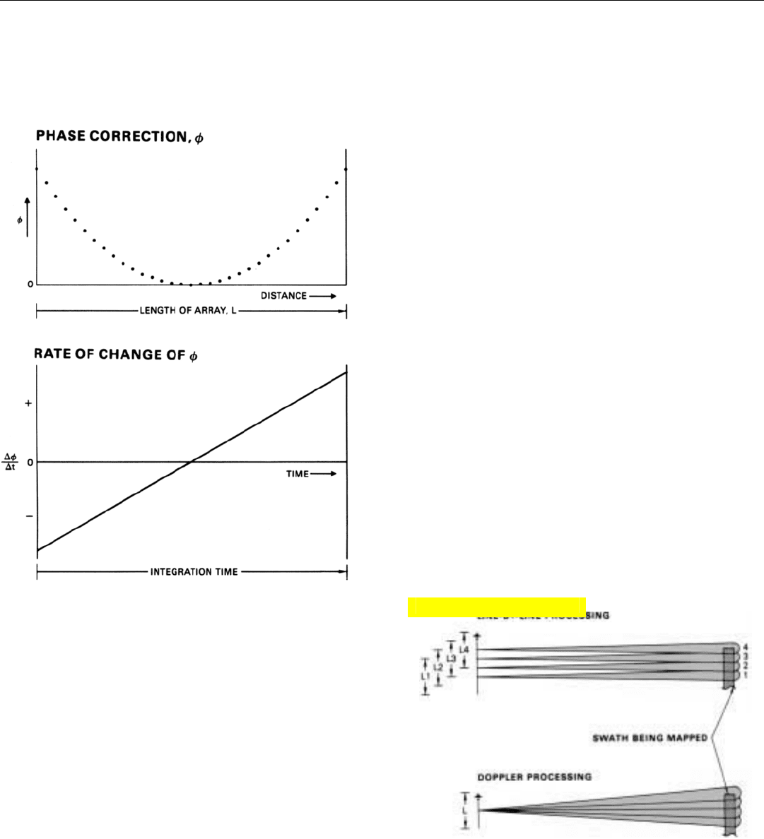
The phase corrections used to remove the slope of the
doppler history curves are exactly the same as the correc-
tions used to focus the array in the line-by-line processor.
This is illustrated by the graphs of Fig. 24. The “U” shaped
curve is a plot of the focusing corrections applied to the
returns received by successive array elements in line-by-
line processing. The straight diagonal line is a plot of the
rate of change of these corrections. Its slope, you will
notice, is identical to the slope of the doppler history of a
point on the ground but is rising, rather than falling. The
same focusing correction that is used by the line-by-line
processor, therefore, converts the linearly decreasing fre-
quency of the return from each point on the ground to a
constant frequency.
While not identical, the beams synthesized by the two
processors are virtually the same. The only difference is in
their points of origin (Fig. 25).
24. Focusing corrections, ø, made to return from successive blocks
of pulses. Rate of change of ø has same slope as doppler his-
tory of point on ground, but is rising rather than falling.
25. Synthetic array beams formed with line-by-line processing and
doppler processing differ only in their points of origin.
With the line-by-line processor, every time the radar
advances one azimuth resolution distance, d
a
, a new beam
is synthesized. Whereas, with the doppler processor, every
time the radar advances one array length, each doppler fil-
ter bank synthesizes a new beam.
Click for high-quality image
CHAPTER 31 Principles of Synthetic Array Aperture Radar
423
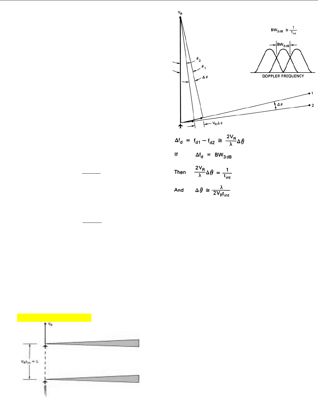
26. The 3-dB bandwidth of a doppler filter is one divided by the
integration time. The difference in doppler frequency, ∆f
d
, of the
returns from two points on the ground is proportional to their
angular separation, ∆
θ
. Equating BW
3 dB
to ∆f
d
yields an
expression for the angular resolution.
27. The length of the array synthesized with doppler processing is the
distance flown during the integration time of the doppler filters.
The beams formed by the line-by-line processor all have
the same azimuth angle (90˚ in the example we have been
considering). But because of the radar’s advance, at the
range being mapped they overlap only at their half power
points.
The beams formed by the doppler filters, on the other
hand, all originate at the same point (center of the array).
But they fan out at azimuth angles such that they overlap
at their half power points.
And how do the azimuth resolutions provided by the
two processors compare?
The 3-dB bandwidth of the doppler filters is roughly
equal to one divided by the integration time (BW
3dB
≅
1/t
int
). As shown in Fig. 26, the difference between the
doppler frequencies of two closely spaced points on the
ground at azimuth angles near 90˚ is twice the radar veloci-
ty times the azimuth separation of the points, divided by
the wavelength.
∆f
d
=
2V
R
∆
θ
λ
Equating ∆f
d
to BW
3 dB
and substituting 1/t
int
for it, we
obtain the following expression for the width of the beam
synthesized by the doppler processor.
∆
θ
=
λ
2V
R
t
int
where
∆
θ
= beamwidth
V
R
= radar velocity
t
int
= integration time
The product of the radar’s velocity and integration time,
V
R
t
int
, is the distance flown during the integration time. As
illustrated in Fig. 27, that is the length of the array, L.
Click for high-quality image
PART VII High Resolution Ground Mapping and Imaging
424
Substituting L for V
R
t
int
and multiplying by the range, R,
we find the azimuth resolution distance to be:
d
a
=
λ
R
2L
This is exactly the same as the azimuth resolution dis-
tance for the line-by-line processor: one half the resolution
distance for a real array of the same length.
So, whether you think of a synthetic array radar in terms
of doppler processing or of conventional array concepts is
largely a question of which view makes the particular aspect
of the array you are concerned with easier to visualize.
Summary
Fine azimuth resolution may be obtained by pointing a
small radar antenna out to one side, storing the returns
received over a period of time, and integrating them so as
to synthesize the equivalent of a long array antenna—SAR.
The points at which successive pulses are transmitted can
be thought of as the elements of this array.
Phase errors due to the greater range of a point on the
ground from the ends of the array than from the center
limit its useful length. The limitation may be removed
through phase correction, a process called “focusing.”
With focusing, azimuth resolution can be made virtually
independent of range by increasing the array length in pro-
portion to the range of the region being mapped.
Since that region must lie within the beam of the real
antenna throughout the entire time the array is being
formed, the length of an array having a fixed look angle is
limited to the width of the beam of the real antenna at the
range being mapped. (This limitation is removed in the
spotlight mode.) The smaller the real antenna, the wider its
beam will be, hence the longer the synthetic array can be
made.
Computation may in some cases be reduced by presum-
ming (when possible) the returns received by blocks of
array elements and applying the phase corrections for
focusing only to the sums.
In any event, computation may be substantially reduced
by integrating the phase-corrected returns in a bank of
doppler filters, with the FFT.
Some Relationships To Keep In Mind
• Minimum resolution requirements:
Road map details: 30 to 50 feet
Shapes: 1/5 to 1/20 of major dimension
• Achievable resolution
d
r
= 500 τ feet
τ = compressed pulse width
Required bandwidth = 1/
τ
d
a
≈
λ
R (for real array)
L
d
a
≈
λ
R (for synthetic array)
2L
(L = array length, same units as λ)

425
SAR Design
Considerations
I
n the last chapter, we saw how SAR takes advantage of
a radar's forward motion to synthesize a very long lin-
ear array from the returns received over a period of up
to several seconds by a small real antenna. We learned
how the array may be focused at virtually any desired range
and how the immense amount of computing required for
digital signal processing may be dramatically reduced
through doppler filtering techniques.
In this chapter, we will consider certain critical aspects
of SAR design which, if not properly attended to, may seri-
ously degrade the quality of the maps or perhaps even
render them useless: selection of the optimum PRF, side-
lobe reduction, compensation for phase errors resulting
from deviation of the radar bearing aircraft from a perfect-
ly straight constant-speed course—called motion compensa-
tion—and the minimization of other phase errors.
Choice of PRF
The PRF must be set low enough to avoid range ambi-
guities, yet high enough to avoid doppler ambiguities—or,
in terms of antenna theory, high enough to avoid problems
with grating lobes.
Avoiding Range Ambiguities. The maximum value of
the PRF is limited by the requirement that returns from the
ranges being mapped not be received simultaneously with
mainlobe returns from any other ranges. This requirement
may be readily met by setting the PRF so that the echo of
each pulse from the far edge of the real antenna's footprint
is received before the echo of the following pulse from the
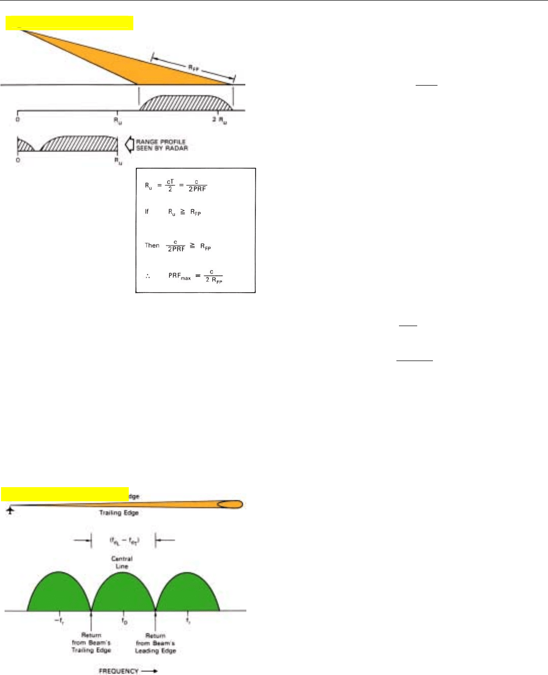
Find:
The maximum PRF a SAR radar can have and still avoid
range ambiguities under these conditions:
• Range segment being mapped may lie anywhere within
footprint of antenna beam.
• Slant range, R
FP,
spanning footprint = 20 nmi
• Speed of light = 162,000 nmi/sec
Calculation:
PRF
max
=
c
2R
FP
=
162,000
2 x 20
= 4050 Hz
PART VII High Resolution Ground Mapping & Imaging
426
near edge—in other words, so that the unambiguous range,
R
u
, is at least as long as the slant range, R
FP
, spanning the
footprint (Fig. 1). That criterion will be satisfied if the PRF
is less than
PRF
max
=
c
2R
FP
where
c = speed of light (162,000 nmi/second)
R
FP
= range spanning footprint of real antenna
1. Range ambiguities may be
avoided by making R
u
greater than the slant range
from the near edge to the
far edge of the real anten-
na’s footprint, R
FP
.
2. To avoid doppler ambiguities, the PRF must exceed the differ-
ence between the doppler shifts at the leading and trailing
edges of the real antenna’s mainlobe.
Sample Computation of PRF
max
As you may be thinking, if only a small segment of R
FP
is
being mapped, cannot higher PRFs in some cases be used?
Certainly. Within a narrow segment in the center of R
FP
, for
instance, ambiguities may be avoided even with PRFs
approaching twice the maximum given by the above
expression.
Avoiding Doppler Ambiguities. The minimum PRF is
generally limited by the requirement that the “lines” of main-
lobe ground return must not overlap. To meet this require-
ment, the PRF must exceed the maximum spread between
the doppler frequencies of points on the ground at the lead-
ing and trailing edges of the mainlobe of the real antenna.
Therefore,
PRF
min
= f
d
L
– f
d
T
where f
d
L
and f
d
T
are the doppler frequencies at the main-
lobe's leading and trailing edges (Fig. 2).
In the case of a narrow azimuth beamwidth, the doppler
spread is approximately equal to 2 V
R
θ
NN
a
/ λ times the sine
Click for high-quality image
Click for high-quality image
