George W. Stimson introduction to Airborne Radar (Se)
Подождите немного. Документ загружается.

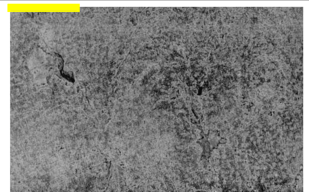
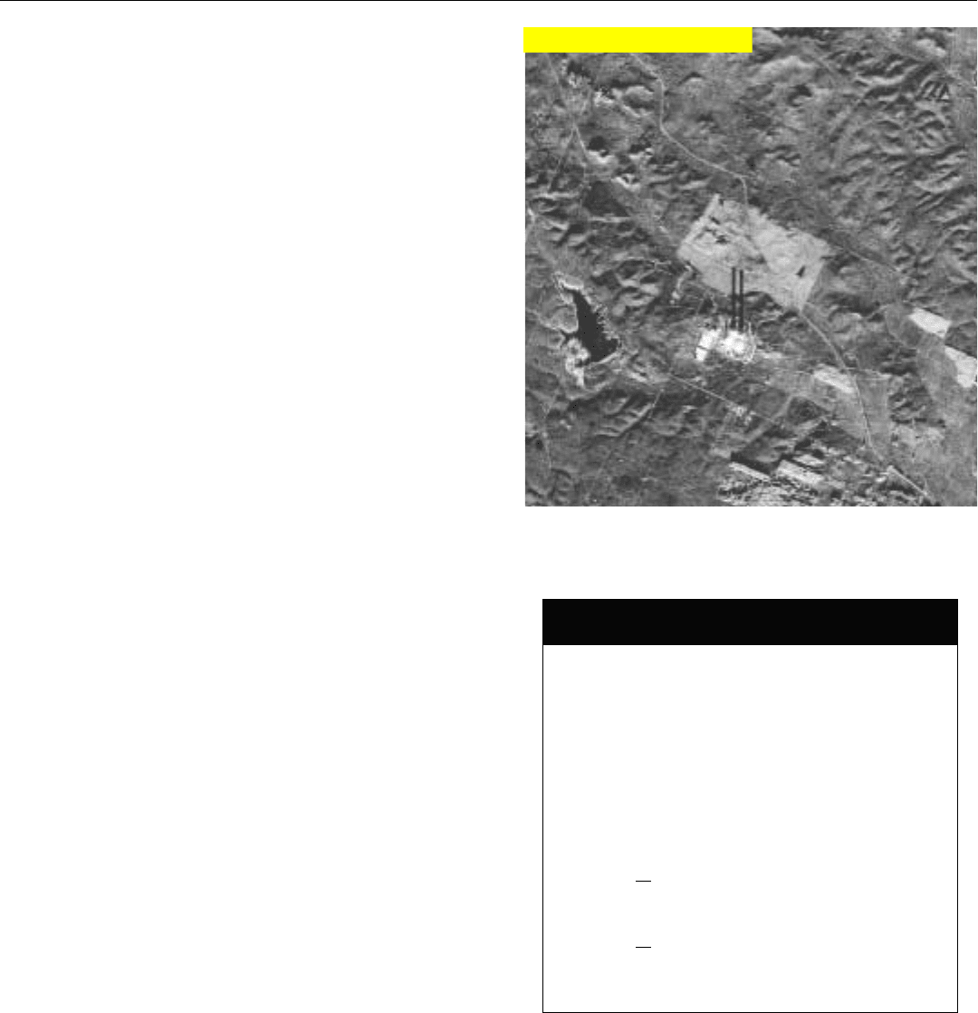
3. Map of a rural area of northeastern China, made by SIR–A radar (similar to SEASAT) carried in Space Shuttle. (Courtesy Jet
Propulsion Laboratory)
PART VII High Resolution Ground Mapping and Imaging
396
In general, to map an area of a given size (Fig. 3), the
amount of processing goes up in proportion to the number
of resolution cells the area contains. If the cells are square,
the number of cells is inversely proportional to the square of
the resolution distance. Cutting it in half, for example,
quadruples the number of cells.
Consider, for example, the SEASAT radar. Orbiting the
earth at a height of 500 miles, in just 100 days of operation
it mapped a total area of 48,000,000 square miles.
2
The
cell size was on the order of 80 by 80 feet, bringing the
total number of cells to around 200 billion. Had the cell
size been reduced to say 10 feet by 10 feet—as would have
been necessary to resolve objects such as houses—the
amount of processing would have increased by roughly 64
times.
Cost. It is not easy to generalize regarding this important
parameter. About all one can say without getting into con-
siderable detail is that, as the resolution is made finer and
the complexity of the signal processing increases, cost goes
up to various degrees. Depending on the situation, at some
point a further increase in resolution becomes prohibitively
expensive. Yet with technological advances, the cost of pro-
viding a given resolution tends to decrease.
2. By comparison, the total area
of North America is only
slightly more than nine mil-
lion square miles.
Click for high-quality image
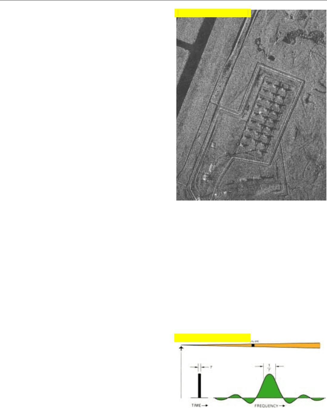
Task of Interpreting the Maps. Superficially, this would
hardly seem an important consideration, but it is. A great
many features of the terrain as well as the objects on it
appear quite differently in a radar map than they do visual-
ly. [Objects on the ground, for instance, are often recog-
nized as much by the size and shape of the shadows they
cast (Fig. 4) as by the brightness and shape of their images.]
Consequently, the amount of time required to interpret the
details in a map of a given region also increases as the reso-
lution is made finer. How much time is available for this
depends on the application.
At one extreme is an application such as SEASAT. Since
this was a research project, the prodigious amount of infor-
mation the radar gathered could reasonably be analyzed
and interpreted over a period of months and years.
At the other extreme are applications such as target loca-
tion in a single-seat attack aircraft. Streaking across the
countryside at a speed of say 800 knots (1350 feet per
second), its radar is called upon to map selected regions for-
ward of the aircraft in real time with resolutions that may be
as fine as a few feet. In addition to other duties, the pilot
must analyze a map in a matter of seconds. To make his job
manageable, only relatively small patches of ground are
mapped, and the maps are temporarily frozen on his display.
When the resolution is increased to enable positive identifi-
cation of specific points on the ground, the area covered by
the individual maps is correspondingly reduced.
Thus, resolution requirements, as well as the sizes of the
areas mapped, vary widely. So, too, do the approaches to
implementation.
Achieving Fine Resolution
In general, fine resolution is more readily obtained in range
than in azimuth. So we’ll consider range resolution first.
Range Resolution. As we saw in Chap. 9, the resolution
that may be obtained in range amounts to about 500 feet
per microsecond of pulse width. Fine range resolution,
therefore, can be obtained simply by narrowing the pulses.
Whereas a 1 microsecond pulse yields a resolution of only
about 500 feet, a 0.1 microsecond pulse yields a resolution
of about 50 feet, and a 0.01 microsecond pulse, a resolu-
tion of about 5 feet.
The principal limitation on how narrow the pulses may
be made is the width of the band of frequencies that can be
passed by the transmitter and receiver (Fig. 5). To pass the
bulk of the power contained in the pulses, the 3-dB band-
width must be on the order of 1/τ hertz, which means that
for a 0.01 microsecond pulse width, the bandwidth must
be on the order of 100 megahertz.
CHAPTER 30 Meeting High Resolution Ground Mapping Requirements
397
4. High resolution map made in real time by the radar of a
small civil aircraft.
5. Range resolution distance decreases with pulse width. As
pulse is narrowed, required bandwidth increases.
Click for high-quality image
Click for high-quality image

EXAMPLE: AZIMUTH RESOLUTION
For a Real Antenna:
3dB
≅
λ
radians
L
d
a
≅
3dBR
R
≅
λR
L
Conditions:
Wavelength (λ).................... 0.1 ft.
Length of Antenna (L)......... 10 ft.
Range (R)........................... 50 nmi
(300,000 ft.)
Calculation:
d
a
≅
0.1 X 300,000
≅
3,000 ft.
10
θ
θ
PART VII High Resolution Ground Mapping and Imaging
398
How readily wide bandwidths may be obtained depends
primarily upon the radar’s operating frequency. For any one
frequency, as the required bandwidth is increased, a point is
ultimately reached beyond which the hardware becomes
increasingly difficult, hence costly, to design and build. As a
very crude rule of thumb, depending upon the particular
situation this point lies somewhere between 3 and 10 per-
cent of the operating frequency. At 10,000 megahertz (X-
band), a bandwidth of 100 megahertz would be only about
1 percent. At 1000 megahertz (L-band), it would be 10 per-
cent. Among hardware items for which bandwidth is more
critical are the antenna (if a planar array is used) and vari-
ous radio frequency components, such as coupled-cavity
TWTs (see page 27).
Naturally, if the peak power and PRF are kept the same,
transmitting extremely narrow pulses greatly reduces the
average transmitted power. But this problem can be avoid-
ed by employing pulse compression (as discussed in Chap.
13). With a pulse compression ratio of 1000:1, a radar can
transmit 10 microsecond pulses and after compression (10
÷ 1000 = 0.01) still achieve a range resolution of 5 feet. The
required bandwidth is of course determined by the com-
pressed pulse width, so it remains the same—in this
example, 100 megahertz.
Azimuth Resolution. Depending upon the application,
the approaches taken to obtaining fine azimuth resolution
vary considerably.
Azimuth resolution distance is roughly equal to the 3-dB
beamwidth of the antenna times the range. The 3-dB
beamwidth (in radians) roughly equals the wavelength
divided by the length of the antenna in units consistent
with the wavelength. So, for a given range, fine resolution
can be obtained by operating at a very short wavelength or
by employing a long antenna, or both. In the atmosphere,
because of severe attenuation at the shorter wavelengths,
the minimum practical wavelength for long-range mapping
is around 3 centimeters (see page 89). In airborne applica-
tions, the length of the radar antenna is usually severely
limited by the dimensions of the aircraft.
Even so, if the maximum range of interest is reasonably
short and the resolution requirements are not too demand-
ing, an antenna of practical size can provide a narrow enough
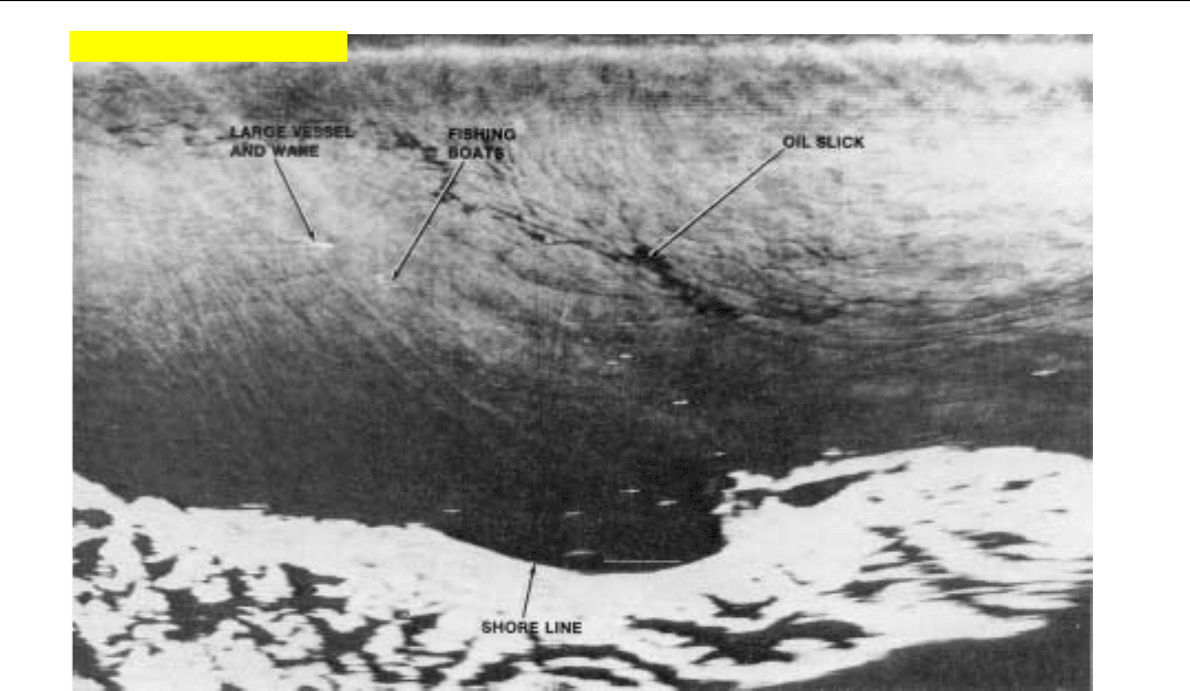
“real” beam to yield quite adequate results. At ranges of up to
10 or 12 nautical miles, for instance, a sidelooking array
radar (SLAR) having a 16-foot-long antenna and operating at
X-band (3 centimeters) can provide resolution adequate for
identifying such features as oil slicks and resolving small craft
(Fig. 6, top of next page).
However, to obtain resolutions fine enough for recogniz-
ing the shapes of even fairly large objects at long ranges, we
must resort either to an impractically long antenna or use
wavelengths so short that the radar must contend with
severe attenuation in the atmosphere. The answer to this
dilemma is to create an antenna of the desired length syn-
thetically—the process called synthetic array (aperture)
radar, SAR.
Synthetic Array (Aperture) Radar
SAR takes advantage of the forward motion of the air-
borne radar to produce the equivalent of an array antenna
which may be thousands of feet long. Moreover, as will be
explained in the next chapter, the beamwidth of this array
is roughly half that of a real array of the same length. The
outputs of the array are synthesized in a signal processor
from the returns received by the real radar antenna over
periods of up to several seconds or more. The processing
may be done either optically or digitally.
3
Optical Processing. The first SAR systems (developed in
the late 1950s and early 1960s) employed optical signal
processors. These can produce very high quality maps and
are intrinsically quite fast. But to date, the inputs and out-
CHAPTER 30 Meeting High Resolution Ground Mapping Requirements
399
6. Map of oil seepage off Santa Barbara, California, made by radar having a 16-foot real-beam sidelooking array. Radar’s flight path
is along top of map. Range to coast is about 15 nmi. At 5 nmi, azimuth resolution is roughly 200 feet. (Courtesy Motorola Inc.)
3. In the 1960s and 1970s, some
SAR systems were developed
which processed the radar
data with analog circuits.
Such processors have since
been supplanted by optical
and digital processors.
Click for high-quality image
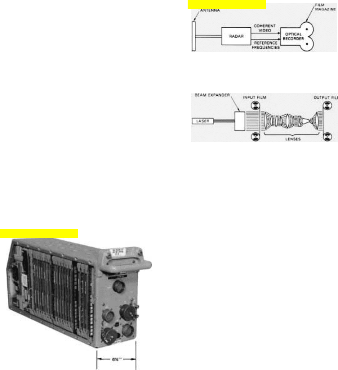
7. Real-time SAR mapping in small aircraft was made possi-
ble by the advent of integrated solid-state circuits, such as
used in this programmable signal processor.
PART VII High Resolution Ground Mapping and Imaging
400
puts have had to be recorded photographically (see panel
above). This requirement has introduced a time lag in the
processing and made the equipment heavy and bulky. Also,
since the optics must be aligned with precision, they are
sensitive to vibration, which can be a problem in an air-
craft. Accordingly in many airborne and all spaceborne
applications, the radar data has been returned to the
ground for processing.
Digital Processing. With the advent of low-cost, high-
speed integrated solid-state circuits in the 1970s, it became
possible to process the video signals digitally in real time,
with lightweight equipment compact enough to be incorpo-
rated in small airborne radars (Fig. 7). This advance greatly
expanded the list of possible SAR applications (see Chap. 3).
Besides solving the problems of speed and equipment
size, digital processing has the advantages of being extreme-
ly accurate and flexible. Once the video signal from the
radar receiver has been accurately digitized and stored, it
can readily be processed to meet a host of operational
requirements.
Literally with the flick of a switch, the range of the area
being mapped can be changed by an order of magnitude,
detailed large-scale maps can be made of areas of special
THE EARLY OPTICAL SAR PROCESSOR
The first airborne SAR systems, developed more than two
decades ago, employed optical processing. For this, an intensity-
modulated scanner photographically records the coherent video
output of the radar receiver in a two-dimensional raster format
on film. This recording is essentially a hologram of the radar
map.
After the film has been developed, coherent light from a laser
is projected through it. An elegant system of lenses focuses the
light onto a second film in such a way as to combine the range
and doppler information contained in the recorded video into an
image.
Although digital processors have compelling advantages over
the conventional optical processors—versatility, small size, high
speed—optical processing is by no means dead. From the
Apollo orbiter, it was used to map the lunar subsurface, and
from the SEASAT satellite and the space shuttle it produced
spectacular maps of vast areas of the Earth’s surface. (In the
case of SEASAT, the radar echoes were radioed directly to
ground stations especially equipped to record them.)
Currently, work is underway that promises to eliminate the need
for photographic recording and thereby make real-time
onboard operation in spacecraft practical.
Click for high-quality image
Click for high-quality image
interest, resolution can be increased (Fig. 8) or decreased as
desired, and maps can be displayed in a variety of formats.
Indeed, the potential capabilities of digital SAR systems
seem limited only by the ever increasing speeds of digital
devices and the ability of the operator to interrupt the
immense amount of data that lies at his fingertips.
Summary
The quality of ground maps is gauged by the size of the
resolution cell—a rectangle (actually a rounded blob)
whose sides are the minimum resolvable difference in
range, d
r
, and azimuth, d
a
. How large the cells can be and
still provide adequate resolution is determined primarily by
the size of the smallest objects that must be recognized.
Resolution requirements are tempered by such consider-
ations as the amount of signal processing that must be
done, the task of interpreting the details of the maps, and
cost. In general, these vary inversely with the square of the
resolution distance.
Fine range resolution may be obtained with reasonable
levels of peak power by using large amounts of pulse com-
pression. Fine azimuth resolution may be obtained by using
short wavelengths and long antennas.
At short ranges, azimuth resolution adequate for many
high resolution applications can be obtained with real-
beam antennas. But to recognize the shapes of even fairly
large objects at long ranges, sufficient resolution can only
be obtained by synthesizing the output of a long array
antenna from the returns received over a period of time by
the real antenna—SAR. The equivalent of an antenna thou-
sands of feet long may thus be realized.
SAR processing may be performed either optically or
digitally. Optical processors are capable of producing very
high quality maps. But to date these processors have
required intermediate photographic film recording. Digital
processing has the advantages of being extremely accurate,
versatile, and fast, and can be implemented with hardware
that is small, rugged, and lightweight.
CHAPTER 30 Meeting High Resolution Ground Mapping Requirements
401
8. SAR map made in real time at long range as evidenced by
long radar shadows of a plant’s stacks (center).
Some Relationships To Keep In Mind
• Minimum resolution requirements:
Road map details: 30 to 50 feet
Shapes: 1/5 to 1/20 of major dimension
• Achievable resolution
d
r
= 500 τ feet
τ = compressed pulse width
Required bandwidth = 1/
τ
d
a
≈
λ
R (for real array)
L
d
a
≈
λ
R (for synthetic array)
2L
(L = array length, same units as λ)
Click for high-quality image

403
Principles of Synthetic
Array (Aperture) Radar
403
I
n the last chapter, we saw how synthetic array radar
(SAR) solves the problem of providing fine azimuth
resolution, even at very long ranges. The signal pro-
cessing, we learned, may be performed either optical-
ly or digitally—digital processing having the advantages of
being extremely flexible and not requiring film processing.
Regardless of which method is used, however, the SAR
principles are the same. They are founded primarily on a
combination of antenna theory and signal processing con-
cepts. In addition, certain aspects of SAR design—such as
resolution, focusing, and the correction of distortion—are
rooted in the theory of optics.
In this chapter, we will examine the SAR principles more
closely and become acquainted with the basic digital pro-
cessing techniques. We will see (1) how the equivalent of a
long array antenna may be synthesized from returns gath-
ered over a period of several seconds by a comparatively
small real antenna, (2) how the array may be focused, (3)
what determines the angular resolution of such an array,
and (4) how the computing load can be reduced by pro-
cessing the returns with doppler filtering techniques.
Basic SAR Concept
As explained in Chap. 30, SAR takes advantage of the
forward motion of the radar to produce the equivalent of a
long antenna. Each time a pulse is transmitted, the radar
occupies a position a little farther along on the flight path.
By pointing a reasonably small antenna out to one side and
summing the returns from successive pulses, it is possible
to synthesize a very long sidelooking linear array.
PART VII High Resolution Ground Mapping and Imaging
404
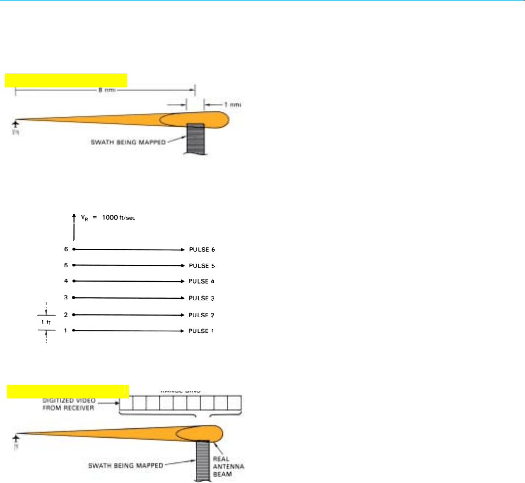
1. Hypothetical operational situation for a SAR radar. With real
antenna trained at fixed azimuth angle of 90
˚ to flight path,
radar maps a 1-mile wide swath at range of 8 miles.
2. Points representing positions of center of antenna when succes-
sive pulses are transmitted. Each point constitutes one “element”
of synthetic array.
3. Returns received by successive elements of the synthetic array are
summed in bank of range bins spanning the range interval being
mapped.
Rudimentary Example (Unfocused Array). Just how the
array is synthesized is perhaps most easily visualized by
considering an extremely simple SAR system in a hypotheti-
cal operational situation.
An aircraft carrying an X-band radar is flying in a straight
line at constant speed and altitude. The radar antenna is
pointed downward slightly and aligned at a fixed angle of
90˚ relative to the flight path (Fig. 1).
As the aircraft progresses, the beam sweeps across a
broad swath of ground parallel to the flight path. Only a rel-
atively narrow portion of this swath, however, is of immedi-
ate interest. That portion, we’ll say, is a strip 1 nautical mile
wide, offset from the flight path by about 8 nautical miles.
The aircraft’s mission requires that the ground within this
strip be mapped with a resolution of about 50 feet. As will
be explained shortly (page 414), to provide 50-foot resolu-
tion at a range of 8 miles, our hypothetical SAR radar must
synthesize an array roughly 50 feet long.
The aircraft’s ground speed, let’s say, is 1000 feet per sec-
ond (600 knots) and the PRF is 1000 pulses per second.
Consequently, every time the radar transmits a pulse, the
center of the radar antenna is one foot farther along the
flight path. The synthetic array can thus be thought of as
consisting of a line of elemental radiators one foot apart
(Fig. 2). To synthesize the required 50-foot long array, 50
such elements are required. In other words, the returns
from 50 consecutive transmitted pulses must be summed.
Typically summing is done after the receiver’s output has
been digitized. A bank of range bins is provided which just
spans the 1 mile range interval being mapped (Fig. 3).
Following every transmission, the return from each resolv-
able range increment within this interval is added to the
contents of the appropriate bin.
This operation corresponds to the summing performed
by the feed structure that interconnects the radiating ele-
ments of a real array antenna. The fundamental difference is
that, with the real array, the return from each range incre-
ment is received simultaneously by all array elements every
time a pulse is transmitted; whereas, with the synthetic
array, the return is collected by the individual elements seri-
ally over the period of time the radar takes to traverse the
array.
The return from the first pulse is received entirely by ele-
ment number one; the return from the second pulse is
received entirely by element number two; and so on.
The result, however, is substantially the same. Provided
that the range is long compared to the array length, the dis-
tance from a patch of ground on the boresight line (perpen-
dicular to the flight path) to each array element is essential-
Click for high-quality image
Click for high-quality image
CHAPTER 31 Principles of Synthetic Array Aperture Radar
405
ly the same. So the echoes received from the patch by all
elements have nearly the same radio frequency phase.
When added up in the range bin corresponding to the
range of the patch, they produce a sum (Fig. 4).
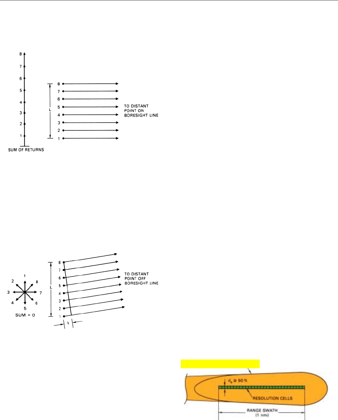
4. Distances from successive array elements to a distant point on
the boresight line are equal, so returns from the point add up
in phase.
5. Distances from successive array elements to a point off the
boresight line are progressively different, so returns from the
point tend to cancel. Null condition is shown here.
6. When returns from 50 pulses have been integrated, contents
of range bins represent the returns from a single row of
range/azimuth resolution cells.
On the other hand, for a ground patch that is not quite on
the boresight line, the distance from the patch to successive
array elements is progressively different. So the echoes
received from the patch by successive elements have pro-
gressively different phases and tend to cancel. The equivalent
of a very narrow antenna beam is thus produced (Fig. 5).
When the returns from the 50 pulses required to form
the array have been integrated, the sum that has built up in
each range bin comes quite close to representing the total
return from a single range/azimuth resolution cell (Fig. 6).
The contents of the bank of bins, therefore, represent the
returns from a single row of resolution cells spanning the 1
mile wide range swath being mapped.
At this point, the contents of the individual range bins
are transferred to corresponding locations in the memory
Click for high-quality image
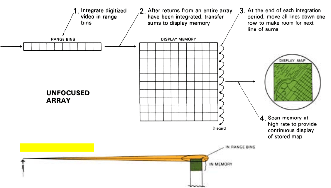
(scan converter) for the radar display (Fig. 7, above). The sig-
nal processor thereupon begins the formation of a new array,
the beam of which will cross the 1-mile-wide swath immedi-
ately ahead of the row of cells that has just been mapped.
Since the map is formed a line at a time, this method of SAR
signal processing is called line-by-line processing.
The display memory stores the integrated returns from as
many rows of cells as can be presented at one time on the
radar display. As the returns from each new row of cells are
received, the stored returns are shifted down one row to
make room for the new data, and the data in the bottom
row is discarded. Throughout the comparatively slow array-
forming process, the data stored in the display memory is
repeatedly scanned at a high rate and presented as a contin-
uous picture on a TV-type display. The operator is thus pro-
vided with a strip map that moves through his display in
real time as the aircraft advances.
To keep the explanation simple, the range to the swath
mapped in this example was deliberately chosen so as to
make the array length equal the desired resolution distance,
d
a
. If the array were longer than d
a
, as it probably would be,
additional storage capacity would have to be provided in
each range bin so that an entire array could be synthesized
every time the radar advanced a distance equal to d
a
.
1
In
essence, though, the operations would be the same as
described here.
PART VII High Resolution Ground Mapping and Imaging
406
7. Steps in the synthesis of a rudimentary unfocused array.
1. If the array were 2d
a
long, the
first 50 returns would be
summed in one memory posi-
tion, the second in another, and
the sum of the two sums would
be transferred to the display
memory. The first sum would
then be dumped and the next 50
returns would be summed. The
sum of that sum plus the second
sum would be transferred to the
display memory, and so on.
Click for high-quality image
