George W. Stimson introduction to Airborne Radar (Se)
Подождите немного. Документ загружается.

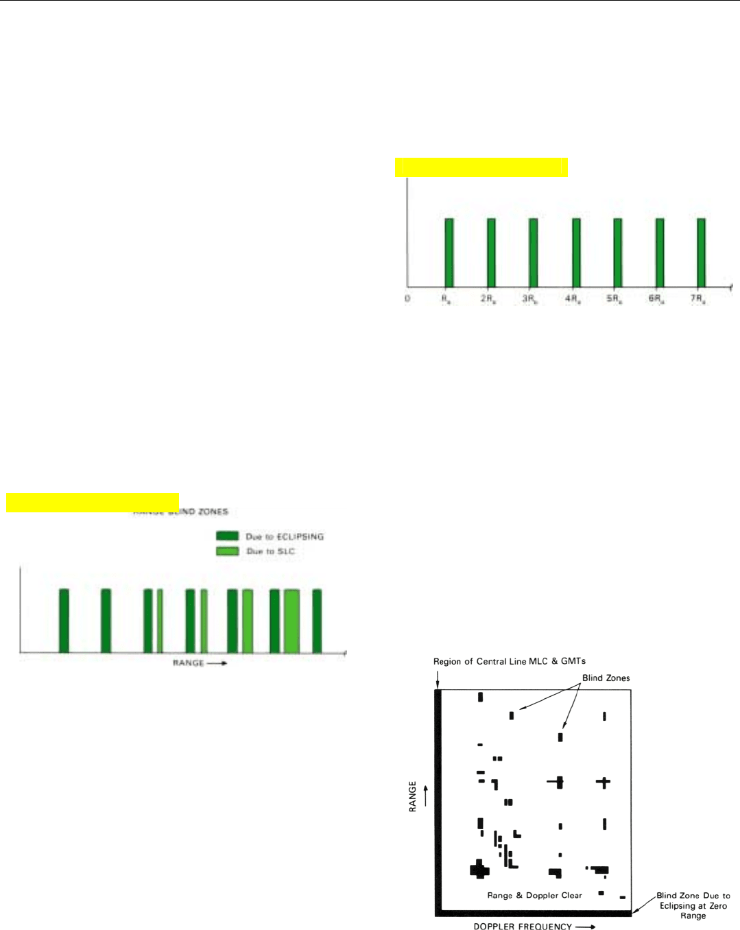
15. Variation in the strength of target return with range. Strength
of the sidelobe clutter with which the target must compete is
superimposed. Blind zones occur where the plots overlap.
PART VI Air-to-Air Operation
362
with the operational situation. A typical waveform, called
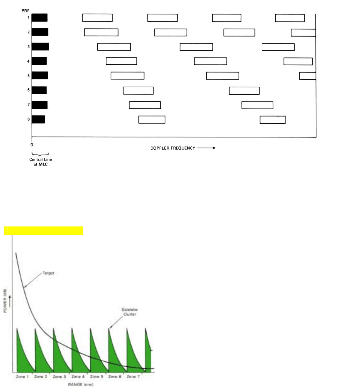
3:8, cycles through 8 PRFs, any 3 of which must be clear
for detection (Fig. 14, above).
Range Blind Zones. These zones bracket the ranges at
which targets will generally not be detected because their
echoes are drowned out by sidelobe clutter simultaneously
received from shorter ranges or are eclipsed by the trans-
mitted pulses.
Just how the blind zones due to sidelobe clutter come
about is best illustrated by a graph such as that shown in
Fig. 15. It contains a plot of the strength of a target’s echoes
as the target’s range increases from a relatively few miles out
to the maximum range of interest. Superimposed over this
plot is a periodically repeated plot of the strength of the
sidelobe clutter received over the course of the interpulse
period. Each repetition of the sidelobe clutter plot repre-
sents the clutter background against which the target
echoes must be detected when the target is in a different
one of the ambiguous range zones into which the true
range profile is divided.
For the particular clutter spectrum illustrated, if a target
is in the first or second range zone, it will be substantially
stronger than any of the sidelobe clutter. If it is in the third
range zone, it will still be stronger than most of the clutter,
but not as strong as the peak produced by the altitude
return and the sidelobe return immediately following it. If
the target is in the fourth range zone, it will be stronger than
the clutter over a smaller portion of the zone, and so on.
14. Doppler blind zones for eight widely spaced PRFs. Any target within the frequency range shown here will be “in the clear” for at least three
PRFs.
Click for high-quality image
At those ranges where the clutter is as strong or stronger
than the target echoes, the target will go undetected, just as
it would if masked by receiver noise. The radar is thus
“blind” to the target.
Obviously, the extent of the range blind zones increases
with the strength of the clutter. The stronger the clutter, the
wider the blind zone will be, and vice versa.
The strength of the clutter, in turn, depends on several
things: the gain of the sidelobes, the nature of the terrain,
the altitude of the radar, etc.
Added to the range blind zones due to strong sidelobe
clutter are the blind zones due to eclipsing (Fig. 16). While
the radar is transmitting (and for a very short recovery time
thereafter), the receiver is blanked. Consequently, if a tar-
get’s echoes are received at such times that they overlap
these periods—as they invariably will be if the target’s range
is a multiple of R
u
—not all of the target return will get
through the receiver, and the target may not be seen. The
resulting blind zones may be narrow enough to be inconse-
quential. But they can become significant if the pulses are
long, as they are in some medium PRF radars.
The combined range blind zones due to sidelobe clutter
and eclipsing for a representative radar are illustrated in
Fig. 17.
CHAPTER 27 Medium PRF Operation
363
16. Range blind zones due to eclipsing by the transmitted pulses.
As the width of transmitted pulses is increased, these zones
become appreciable.
17. Combined range blind zones due to eclipsing and sidelobe
clutter for a representative medium PRF radar.
18.
Region in which a representative radar is both range clear and
doppler clear for at least three of eight widely spaced PRFs.
As with doppler blind zones, the positions of the range
blind zones shift with changes in the PRF. Fortunately, the
shift is such that the same PRF switching as is used to
reduce doppler blind zones will also largely reduce range
blind zones (Fig. 18).
Bear in mind, though, that it is not enough for a target to
be in a doppler clear region for one set of PRFs and in a
range clear region for another. For a target to be detected, it
must be in both a doppler clear region and a range clear
region for the same set of PRFs. If the target’s doppler fre-
quency falls in a doppler blind zone, its echoes will not get
through a doppler filter and be detected even though it is in
a range-clear region. And if the target is in a range blind
Click for high-quality image
Click for high-quality image
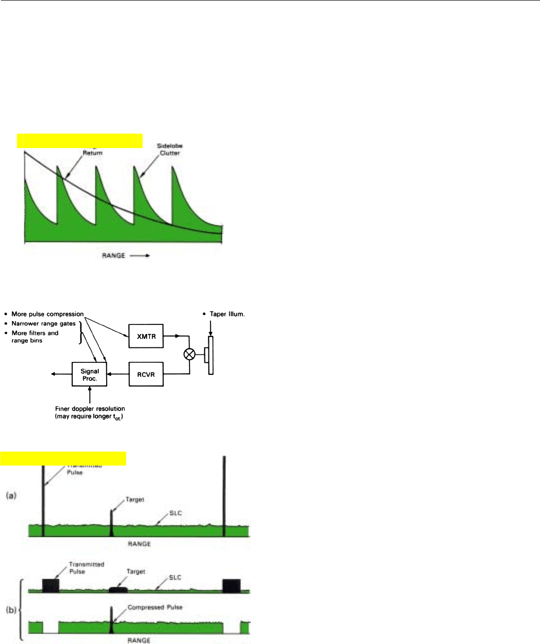
19. As a targets‘ range is increased its echoes may eventually be
engulfed in sidelobe clutter, unless special measures are
taken to minimize it.
20. Measures that can be taken to reduce sidelobe clutter.
21. Two ways of reducing sidelobe clutter through range resolution:
(a) transmit very narrow pulses of high enough peak power to
provide adequate detection range; (b) transmit wider pulses of
the same average power and use pulse compression to provide
the desired range resolution.
PART VI Air-to-Air Operation
364
zone, even though its echoes may get through a filter, they
will be buried in the accompanying sidelobe clutter, which
will drive the detection threshold up to a point where the
target will not be detected.
It should be noted that the foregoing discussion of blind
zones all pertains to search. In single-target tracking, there
are many PRFs to choose from to avoid blind zones.
Minimizing Sidelobe Clutter
Clearly, at medium PRFs, sidelobe clutter must be kept
to a minimum. For it not only determines the extent of the
range blind zones, but limits the maximum detection range.
Since most of the sidelobe clutter comes from relatively
short ranges, the background of clutter against which tar-
gets must be detected is generally stronger than the back-
ground noise falling in the passband of a doppler filter.
Therefore, no matter how powerful the radar or how great a
target’s radar cross section, if the target’s range is continu-
ously increased (Fig. 19), a point will ultimately be reached
where its echoes become lost in the clutter. The stronger
the clutter, the shorter this range will be.
What, then, can be done to minimize the sidelobe clut-
ter? Several things (Fig. 20). Without question, the most
important measure is to design the radar antenna so that
the gain of its sidelobes is low. In fact, this is essential. As
described in Chap. 8, sidelobes can be reduced by taper-
ing the distribution of radiated power across the antenna.
For a given level of sidelobe clutter in the receiver out-
put, the amount of clutter with which a target’s echoes must
compete can be further reduced by narrowing the radar’s
pulses and correspondingly narrowing the range gates. If,
for example, the pulse width is reduced by a factor of 10,
the sidelobe clutter will be reduced by roughly the same
ratio. Narrowing the pulses, of course, requires adding
more range gates and forming more doppler filters—a sepa-
rate bank of filters being required for every range gate.
By employing pulse compression, the narrowing can be
accomplished without reducing the average transmitted
power (Fig. 21). A common practice is to maximize the
average power by making the transmitted pulses as wide as
possible without incurring an unacceptable loss due to
eclipsing. Enough pulse compression is then provided to
achieve the desired range resolution.
An alternative approach, which minimizes eclipsing, is to
transmit very narrow pulses of higher peak power.
The sidelobe clutter with which a target must compete
can be still further reduced by narrowing the passbands of
the doppler filters. For that, the return from more pulses
must be integrated by the filters—the time-on-target must
Click for high-quality image
Click for high-quality image
be sufficient to permit this—and more filters, magnitude
detectors, and threshold detectors must be provided.
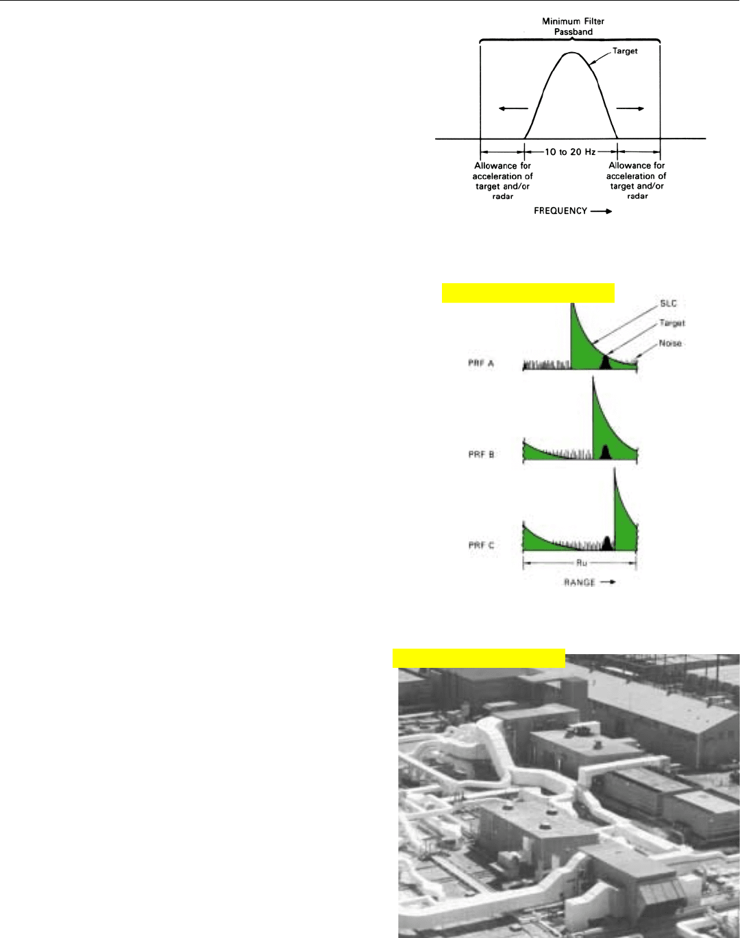
To retain all of the power in the target return, of course,
the filters must still be wide enough to pass the spectrum of
frequencies over which the power is spread. The width of
this spectrum varies from target to target, but is on the
order of 10 to 20 hertz. Usually, the filters must be made
wider than this to minimize filter straddle loss, as discussed
in Chap. 18. Also, it may be necessary to allow for possible
changes in doppler frequency due to acceleration of one or
both aircraft during the filter formation time (Fig. 22).
Through techniques such as those outlined in the forego-
ing paragraphs, sidelobe clutter may be reduced to a point
where it falls below the noise level at the ends of the inter-
pulse period (Fig. 23). The detection ranges of targets
appearing there will then be limited only by noise.
By switching among a large enough selection of PRFs,
these clutter-free regions can be shifted about so that the
detection range of virtually all targets will be limited only
by noise. As more PRFs are added, of course, the available
integration time for each PRF decreases, and this decrease
limits the detection range.
Detection ranges achievable with medium PRFs are thus
invariably somewhat less than those achievable under simi-
lar conditions with high PRFs against nose-aspect targets or
with low PRFs in those situations where mainlobe clutter is
not a problem.
Sidelobe Return from Targets of Large RCS
One important form of sidelobe return we have not yet
considered is that from structures on the ground—build-
ings, trucks, etc. having exceptionally large radar cross sec-
tions. As explained in Chap. 22, even when in the side-
lobes, such structures can return echoes every bit as strong
as those received from an aircraft in the mainlobe (Fig. 24).
If the ground target’s doppler frequency falls in the filter
bank’s passband—as it most often will when the ground
target is in a sidelobe—the ground target will be detected
no differently than if it were an aircraft in the mainlobe.
Since these unwanted targets are nearly point reflectors,
no amount of range or doppler resolution will make them
less likely to be detected. On the contrary, the greater the
resolution provided, the greater the extent to which the sur-
rounding sidelobe clutter will be attenuated and the more
prominently the point targets will protrude above it.
While a radar is vulnerable to such targets when operat-
ing at low PRFs, it is much more vulnerable when operating
at medium PRFs because of the more severe range ambigui-
CHAPTER 27 Medium PRF Operation
365
22. Passband of a doppler filter must at least be wide enough to
accommodate the target return and allow for changes in
doppler frequency during the integration period.
23. By switching among enough PRFs, the sawtooth pattern of
sidelobe clutter can be shifted about so that virtually every tar-
get may be detected against a background only of noise.
24. Because of range and doppler ambiguities at medium PRFs, a
radar is vulnerable to unwanted ground targets.
Click for high-quality image
Click for high-quality image
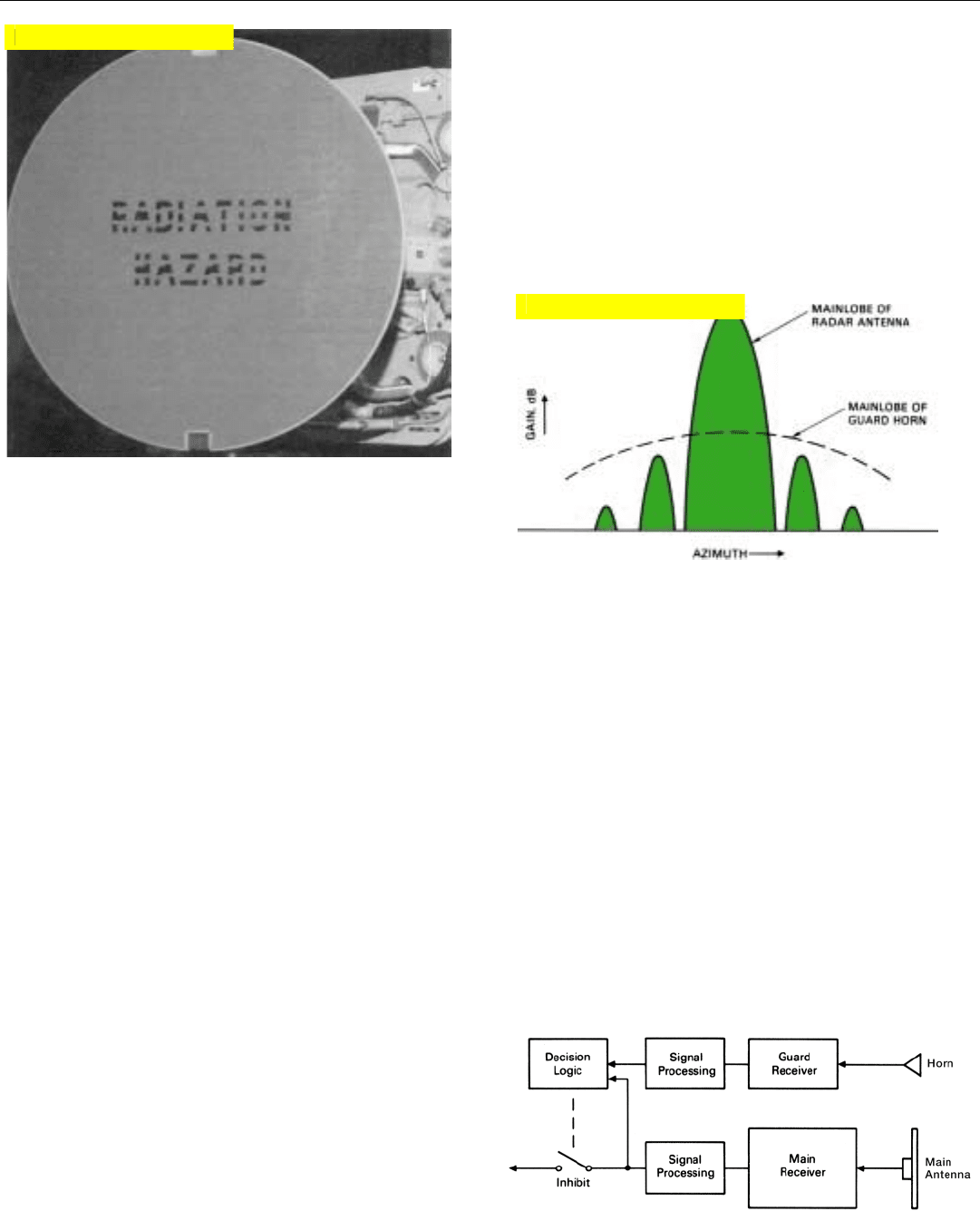
25. Antenna of a medium PRF radar. Note horn antenna for guard
receiver.
PART VI Air-to-Air Operation
366
ties. Some special means, therefore, must be provided to
keep these targets from reaching the radar display.
One way of dealing with these unwanted targets is to pro-
vide the radar with a guard channel. In essence it consists of
a separate receiver whose input is supplied by a small horn
antenna mounted on the radar antenna (Fig. 25).
The width of the horn’s mainlobe is sufficient to encom-
pass the entire region illuminated by the radar antenna’s
principal sidelobes, and the gain of the horn’s mainlobe is
greater than that of any of the sidelobes (Fig. 26).
2. Mainlobe return from the
unwanted ground target will,
of course, fall in the rejection
notch of the clutter canceller.
If the return is extremely
strong, however, a detectable
fraction of it may get through.
Any detectable target in the radar antenna’s sidelobes,
therefore, will produce a stronger output from the guard
receiver than from the main receiver.
On the other hand, because the gain of the radar anten-
na’s mainlobe is much greater than that of the horn, any
target in the radar antenna’s mainlobe will produce a much
stronger output from the main receiver than from the guard
receiver.
Consequently, by comparing the outputs of the two
receivers and inhibiting the output of the main receiver
when the output of the guard receiver is stronger (Fig. 27),
we can prevent any targets that are in the sidelobes from
appearing on the radar display.
2
26. Gain of horn‘s mainlobe is greater than that of the radar
antenna‘s sidelobes but less than that of radar antenna‘s
mainlobe.
27. Output of main receiver is inhibited when a target is detected
simultaneously through guard channel and main receiver
channel.
Click for high-quality image
Click for high-quality image

CHAPTER 27 Medium PRF Operation
367
MEDIUM PRFs
ADVANTAGES LIMITATIONS
1. Good all-aspect capa- 1. Detection range
bility—copes satisfac- against both low and
torily with both main- high closing-rate tar-
lobe and sidelobe gets can be limited by
clutter. sidelobe clutter.
2. Ground-moving targets 2. Must resolve both
readily eliminated. range and doppler
ambiguities.
3. Pulse delay ranging 3. Special measures
possible. needed to reject side-
lobe return from
strong ground targets.
Summary
In medium PRF operation, the PRF is usually set just
high enough to spread the mainlobe clutter lines so that
mainlobe clutter and any ground moving targets (GMTs)
can be rejected without rejecting the return from an unrea-
sonably high percentage of targets. Range ambiguities are
then still sufficiently mild that, through a combination of
range and doppler discrimination, the background of side-
lobe clutter against which the target echoes must be detect-
ed can be reduced to an acceptable level.
Because of the increased separation of the mainlobe clut-
ter lines, doppler blind zones can be largely eliminated by
switching among a few fairly widely spaced PRFs. Because
distant targets must compete with close-in sidelobe clutter,
the peaks of this clutter produce range blind zones. If the
clutter is not too strong, these as well as blind zones due to
eclipsing can largely be eliminated by the same PRF switch-
ing as is used to eliminate doppler blind zones. But even in
the doppler clear regions, sidelobe clutter usually limits
detection range.
It is essential that a low sidelobe antenna be used.
Sidelobe return can be further reduced by increasing the
range and doppler resolution. To eliminate sidelobe return
from ground targets of exceptionally large radar cross sec-
tion, a guard channel may be provided.
369
High PRF Operation
1. High PRF operation spreads the clutter bands far enough
apart to open up a clutter-free region in which high closing
rate targets will appear.
A
high PRF is one for which the observed doppler
frequencies of all significant targets are unam-
biguous. The observed ranges, however, are gen-
erally highly ambiguous.
High PRF operation has three principal advantages. First,
since doppler frequencies are unambiguous, mainlobe clut-
ter can be rejected without rejecting any target echoes
whose doppler frequencies are different from that of the
clutter. Second, by employing a high enough PRF, the
“lines” (more realistically, bands) of the clutter spectrum
can be spread far enough apart to open up an entirely clut-
ter-free region between them, where high closing rate
1
(nose-aspect) targets will appear (Fig. 1). Third, transmitter
duty factors can be increased by increasing the PRF rather
than the pulsewidth, thereby enabling high average powers
to be obtained without the need for large amounts of pulse
compression or very high peak powers.
Detection range, of course, increases with the ratio of the
signal energy to the energy of the background noise and
clutter. By employing a high duty factor, high PRF wave-
form, therefore, long detection ranges can be obtained
against nose-aspect targets even in a clutter environment.
However, where strong sidelobe clutter is encountered,
detection ranges against low-closing-rate (tail-aspect) tar-
gets may be impaired because of range ambiguities.
In this chapter, we will consider a high duty factor, high
PRF waveform, see what must be done to separate targets
from ground return, and learn how the signal processing is
done. We’ll then take up the problem of range measure-
ment, eclipsing loss, and the steps which may be taken to
improve performance against low-closing-rate targets.
1. Targets whose closing rates
are greater than the radar’s
ground speed.
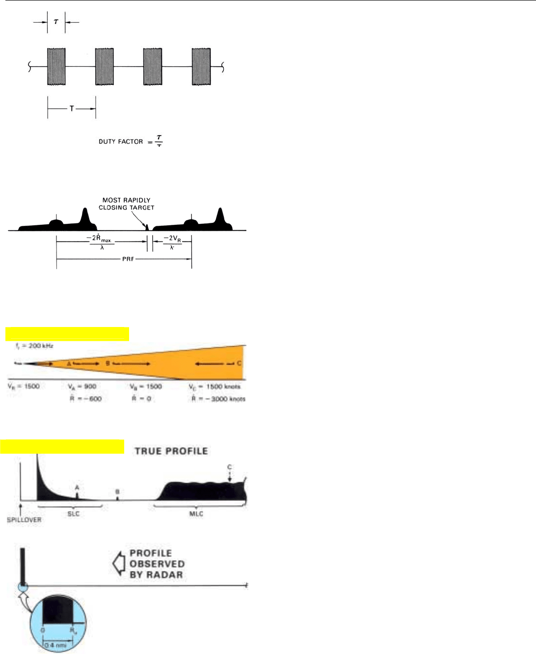
5. Range profile for the representative flight situation. Returns
from virtually all ranges are collapsed into a band of
observed ranges less than half a mile wide.
PART VI Air-to-Air Operations
370
High PRF Waveform
A representative high duty factor, high PRF waveform is
shown in Fig. 2. Because the radar receiver must be
blanked during transmission and the duplexer has a finite
recovery time, the maximum useful transmitter duty factor
is generally somewhat less than 50 percent.
As for the PRF, if the clutter-free (“doppler clear”) region
is to encompass all significant high-closing-rate targets, the
PRF must be greater than the sum of the
• Doppler frequency of the most rapidly closing target
• Maximum sidelobe clutter frequency (determined by
the radar’s velocity)
The maximum sidelobe clutter frequency is twice the
radar velocity divided by the wavelength. The target
doppler frequency is twice the target closing rate divided by
the wavelength (Fig. 3).
The shorter the wavelength, of course, the higher the
doppler frequencies of the clutter and the target will be;
hence, the higher the required PRF. Typically, in fighter
applications at X-band frequencies the PRF is on the order
of 100 to 300 kilohertz.
Isolating the Target Returns
To get a clear picture of the problem of differentiating
between target echoes and ground clutter and of isolating
the echoes from the clutter and as much of the background
noise as possible, we’ll look at the range and doppler pro-
files for the representative flight situation shown in Fig. 4.
We will assume this time that the radar is operating at a
PRF of 200 kilohertz with a duty factor of 45 percent, that
the aircraft carrying the radar has a ground speed of 1500
knots, and that echoes are being received from three tar-
gets. Targets A and B are flying in the same direction as the
radar. Target A has a closing rate of 600 knots; Target B has
zero closing rate. The third target, C, is approaching the
radar from long range and has a closing rate of 3000 knots.
Range Profile. This profile is illustrated in Fig. 5. Its
width as observed by the radar (R
u
) is less than half a nauti-
cal mile (80 ÷ 200 = 0.4 nmi). Into this narrow interval is
collapsed (telescoped) the return from every 0.4 mile incre-
ment of range out to the maximum range from which
return is received: all of the mainlobe clutter, the altitude
return, all of the remaining sidelobe clutter, plus the trans-
mitter spillover and the background noise. Buried in the
midst of this pileup are the echoes from the three targets.
Virtually the only way they can be separated from it, or
from each other for that matter, is to sort out the return by
doppler frequency.
2. High duty factor, high PRF waveform typical of those used in
radars for fighter aircraft. Duty factor is generally somewhat
less than 50 percent.
3. For the doppler clear region to encompass all high-closing-
rate targets, the PRF must exceed the doppler frequency of the
most rapidly closing target, plus the maximum sidelobe clutter
frequency.
4. Representative flight situation. Target A has a low-closing-rate;
target B, zero-closing-rate; target C, high-closing-rates.
Click for high-quality image
Click for high-quality image
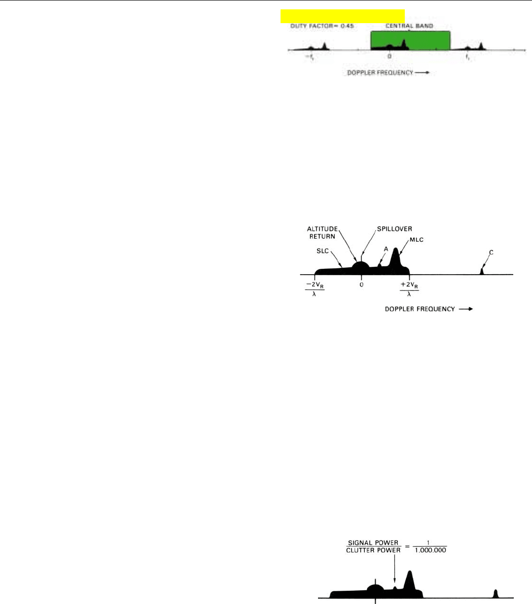
Doppler Profile. This profile is shown in Fig. 6. As with
low and medium PRF operation, the profile is a composite
of the entire true doppler spectrum of the radar return,
repeated at intervals equal to the PRF. But there is one
important difference. Since the width of the spectrum is
less than the PRF, the repetitions (bands) do not overlap.
Also, in bands on either side of the central one, the
amplitude of the radar return is noticeably reduced. With a
duty factor of 0.45, the nulls in the envelope within which
the spectral lines fit are only 2.2f
r
above and below the cen-
tral line. So, for each component of the return, there are
only two spectral lines between the central one and the
nulls on either side. The amplitudes of these lines are con-
siderably less than that of the central line.
Examining the central band closely, Fig. 7, we can clearly
identify the following features: transmitter spillover, alti-
tude return, sidelobe clutter, and mainlobe clutter. The
width of the sidelobe clutter region varies with the radar
velocity. The width and frequency of the mainlobe clutter
line vary continuously with the antenna look angle as well
as with the radar velocity.
Barely poking up above the sidelobe clutter are the
echoes from the low-closing-rate target, Target A. In the
clear between the high frequency end of the sidelobe clutter
region and the low frequency end of the next higher band
are the echoes from the high closing rate target, Target C.
Provided the other clutter is removed, this target need only
compete with thermal noise to be detected.
The echoes from the zero-closing-rate target (Target B)
are nowhere to be seen. Actually, they are there, But they
have merged with the combined altitude return and trans-
mitter spillover, which has zero doppler frequency.
Rejecting the Strong Clutter. One needn’t contemplate
Fig. 7 very long to conclude that a logical first step in iso-
lating the target return is rejecting the spillover and strong
ground return—mainlobe clutter (MLC) and altitude
return. In fact, this is essential. Why?
Where little or no range discrimination is provided, this
return may be as much as 60 dB stronger than a target’s
echoes (Fig. 8). Sixty dB, remember, is a power ratio of
1,000,000 to 1; a doppler filter bank alone simply cannot
cope with such strong clutter. Even though the clutter may
be widely separated from a target’s frequency, the attenua-
tion that a doppler filter provides outside its passband is
insufficient to keep the clutter from drowning out the tar-
get, albeit centered in the passband.
If we wish to search for targets in both sidelobe clutter
and doppler clear regions, the spillover and altitude return,
which have essentially zero doppler frequency, must be
CHAPTER 28 High PRF Operation
371
6. Doppler profile for the representative flight situation.
Repetitions of the true profile do not overlap.
7. Central band of the doppler profile.
8. Power of mainlobe clutter and altitude return may be 60 dB
stronger than that of a target’s echoes.
Click for high-quality image
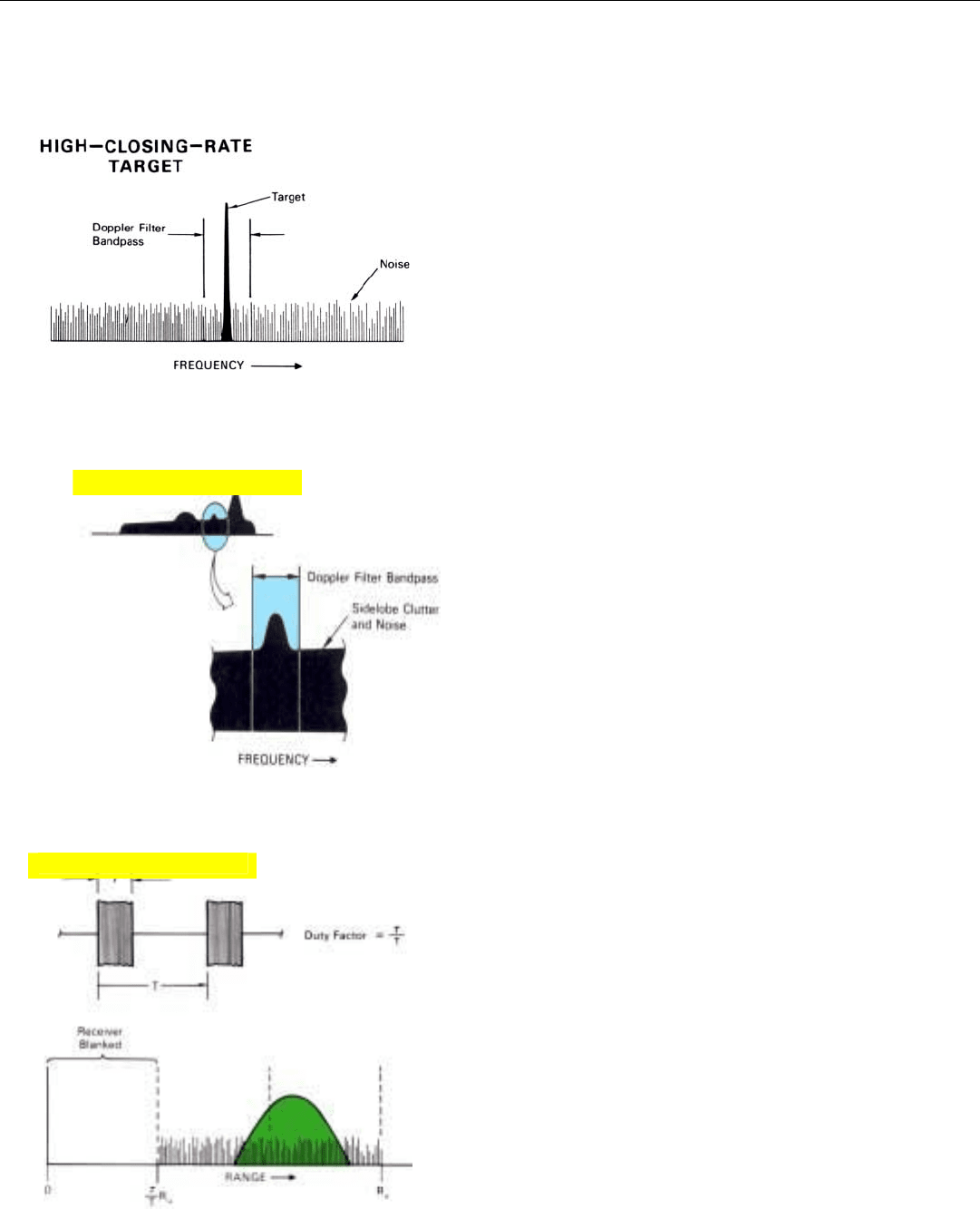
11. If the duty factor is less than 50 percent, the amount of noise
or clutter with which a target must compete may be reduced
by providing more than one range gate.
PART VI Air-to-Air Operations
372
rejected separately from the mainlobe clutter, which has a
widely varying frequency.
Doppler Resolution. Once the strong clutter has been
removed, the target echoes can be isolated through doppler
filtering—just as in medium PRF operation. The role of the
doppler filters, though, is slightly different for high-closing-
rate targets than for low.
In the case of high-closing-rate targets—those having
closing rates greater than the radar’s ground speed—the
doppler filters serve three basic functions. First, they sepa-
rate the target echoes from all of the remaining sidelobe
clutter, as well as from the residual mainlobe clutter.
Second, by reducing the spectral width of the background
noise accompanying the echoes of any one target, the filters
reduce the amount of noise with which the echoes must
compete (Fig. 9). Third, they isolate the echoes received
from different targets—provided they have sufficiently dif-
ferent doppler frequencies. It is this noise that ultimately
limits the maximum range at which high-closing- rate tar-
gets may be detected. The more the noise is reduced, the
greater the detection range will be.
In the case of low-closing-rate targets, the doppler filters
perform the same target isolation function. But they cannot
completely separate a target’s echoes from the sidelobe clut-
ter (Fig. 10). For some of this clutter has the same doppler
frequency as the target. As with both high- and low-closing-
rate targets in medium PRF operation, it is generally this
clutter which ultimately limits the range at which low-clos-
ing-rate targets may be detected.
Because of the more severe range ambiguities, however,
the competing clutter is much stronger than that encoun-
tered under the same conditions in medium PRF operation.
For this reason, when high PRFs are used in situations
where appreciable sidelobe clutter is received, detection
ranges against low-closing-rate targets are degraded.
Range Gating. With duty factors approaching 50 per-
cent, there is little or no possibility of isolating the return
from different ranges with range gates. Receiver blanking,
in fact, serves the function of a single range gate; none
other need be provided.
However, if the duty factor is much less than 50 percent,
i.e., if the interpulse period is much more than twice the
pulse width, the opportunity for employing additional
range gating arises (Fig. 11). By providing more than one
range gate, the amount of noise—or sidelobe clutter—with
which a target must compete may be reduced, and the loss
in signal-to-noise (or clutter) ratio due to targets not being
centered in the gate may be cut. The lower the duty factor,
the greater the improvement that may be realized by adding
9. Doppler filter isolates the high-closing-rate target from all other
returns and all but the immediately surrounding noise.
10. Low-closing-rate target must compete with immediately sur-
rounding sidelobe clutter, much of which may come from a far
closer angle than the target’s.
Click for high-quality image
Click for high-quality image
