George W. Stimson introduction to Airborne Radar (Se)
Подождите немного. Документ загружается.

PART VI Air-to-Air Operation
384
vers, to eliminate as much noise as possible without intro-
ducing excessive lag.
Control is the generation of a command calculated on the
basis of the filter’s outputs to reduce the tracking error as
nearly as possible to zero.
Response is the response of the hardware and/or software
to which the command is given. The difference between the
response and the current actual value of the parameter
feeds back to the input, closing the loop, and the entire
process repeats. Through successive iterations, the parame-
ter may be tracked with extreme precision.
Special Terminology. Before proceeding further, it will be
well to introduce two important technical terms used by
tracking-loop designers: discriminant and estimate.
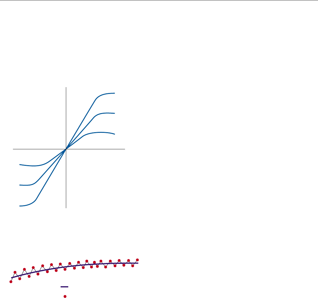
Discriminant is the term for the calibration of the mea-
surement function. It is commonly represented by a plot of
the output of the hardware and/or software that performs
the measurement versus the true value of the tracking error
(Fig. 3). The slope of the linear portion of the plot deter-
mines the sensitivity of the measurement. Typically, the
slope increases as signal-to-noise ratio increases.
An important feature of discriminants is that they are
dimensionless (normalized). Consequently, precise mea-
surement of voltage or power levels isn’t required. More-
over, except for the influence of signal-to-noise ratio, the
measured values of the tracking error don’t vary with signal
strength. They are independent of the target’s size, its range,
its maneuvers, and fluctuations of its RCS. If desired,
though, a discriminant can be given a dimension simply by
multiplying it by a precomputed constant.
Estimate is the term applied to the value of any parame-
ter that is
(a) measurable only in combination with corrupting
interference—e.g., thermal noise (Fig. 4), or
(b) not directly measurable, e.g., range rate based on a
sequence of range measurements.
According to this definition, virtually every parameter mea-
sured or computed by a radar, no matter how precisely, is
an estimate.
With these definitions in mind, let us take a quick look
at the angle-tracking loops commonly incorporated in sin-
gle-target tracking modes.
Range-Tracking Loop. This loop has two primary goals:
to continuously and accurately determine the target’s cur-
rent range, and to keep a range-gate—actually two adjacent
sampling times—centered on the target’s echoes to isolate
them for doppler and angle tracking.
True Value
(+)
(–)
Measured Value
SNR
(dB)
30
10
0
(+)
(–)
3. A tracking discriminant may be represented by a normalized
plot of the measured value of the tracking error versus the true
value. The steeper the linear portion of the discriminant, the
more sensitive the measurement.
Estimate
Measurements
4. The value of any parameter that can only be determined on
the basis of successive measurements which are corrupted by
noise or other interference is termed an estimate.
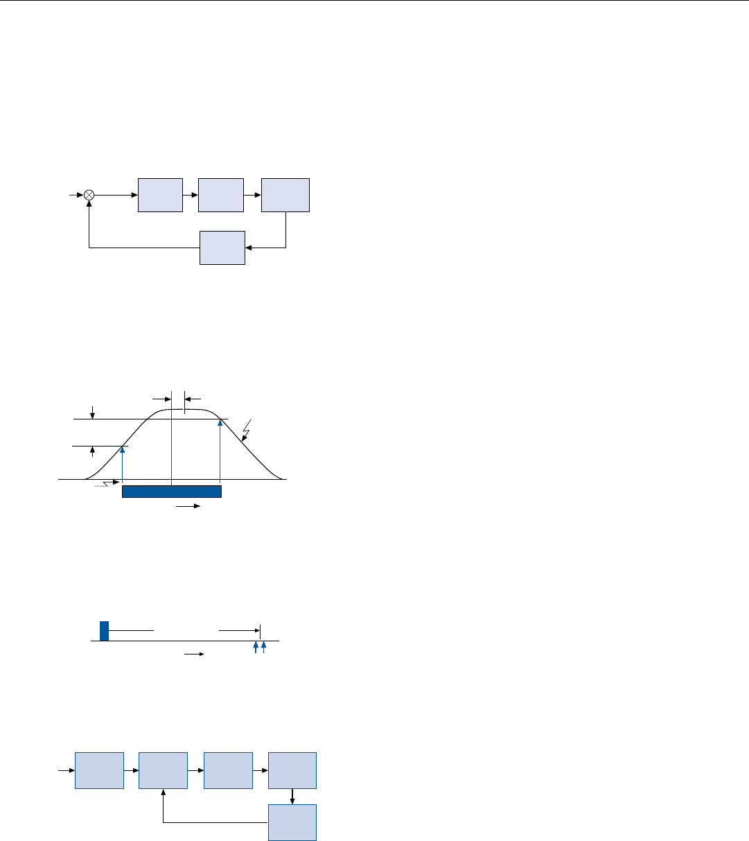
To facilitate forming the range discriminant, the video
output of the receiver is passed through a low-pass filter,
stretching the target’s echoes to roughly twice the radar’s
pulse width and giving them a more “rounded” shape.
1
Assuming that the video is sampled at intervals equal to the
pulse width, this results in two samples being taken of each
target echo and in the amplitudes of the samples differing
in proportion to the displacement of the range gate from
the center of the echo (Fig. 5). Because successive samples
are stored in separate range bins, the first sample is called
the early range bin; the second, the late range bin.
The goal being to keep the range gate centered on the
target echoes, the range discriminant is formed by measur-
ing the difference between the amplitudes of the two sam-
ples: R
L
– R
E
. The measurement is normalized by dividing it
by the sum of the amplitudes (Fig. 6). The result is sup-
plied to the range filter.
CHAPTER 29 Automatic Tracking
385
1. The filter removes the pulse’s
higher frequency compo-
nents, which contribute to the
sharpness of its leading and
trailing edges.
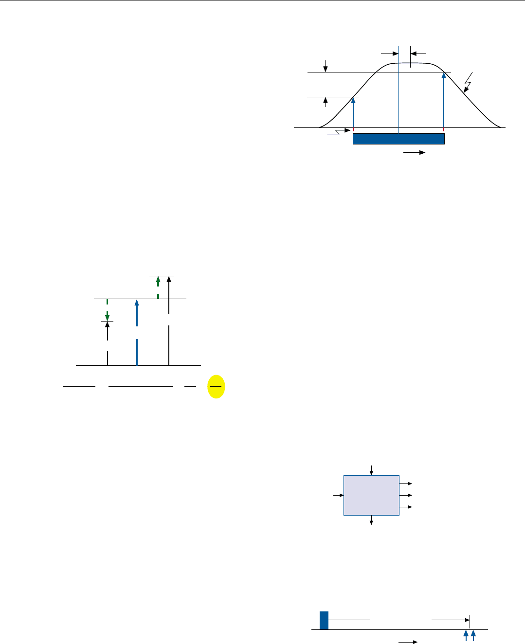
On the basis of the range discriminant and the previous
range-gate command, the range filter produces best esti-
mates of the target’s range and range rate, a measure of the
range acceleration, and a new range-gate command (Fig. 7).
The range-gate command is essentially a prediction of
what the target’s range will be when the next target echo is
sampled. Typically, the command is formed by taking the
filter’s latest estimates of the target’s range and range rate
and linearly extrapolating the range.
To carry out the range-gate command, the predicted tar-
get range is first corrected for radar peculiarities (such as
sampling-time granularity) and distortion of the pulse-
shape in going through the receiver and pulse-stretching
low-pass filter. The prediction is then converted into units
of time measured from the trailing edge of the immediately
preceding transmitted pulse, hence to the estimated arrival
time of the next echo (Fig. 8).
Time
R
E
Stretched Envelope
of Target Echo
Sampling
Times
R
L
= Magnitude of sample in late range bin
R
E
= Magnitude of sample in early range bin
e = Tracking error
R
L
e
Range Gate
e ∝ R
L
– R
E
5. The range gate is centered between two adjacent sampling
times. To track a target in range, the sampling times must be
shifted to center the range gate on the target’s echoes. The
tracking error, e, is proportional to the difference between
the early and late samples, R
E
and R
L
.
e
R
E
∆R =
R
L
– R
E
R
L
+ R
E
=
(M +
e
) – (M –
e
)
(M +
e
) + (M –
e
)
=
2
e
2M
RANGE DISCRIMINANT, ∆R
R
L
e
e = Tracking error = 2
e
M = Mean value of samples
e
2M
=
M
6. Range-tracking error is proportional to the difference between
the magnitudes of the samples stored in the early and late
range bins. Dividing by their sum yields a nondimensional
ratio of the error to twice the mean of the samples.
∆R
Range*
Range Rate*
Range Acceleration*
*Best estimate
Range
Filter
Previous
Range Gate
Command
New Range Gate
Command
7. Inputs and outputs of the range filter. ∆R is the range discrimi-
nant.
Time
Range
Gate
Time Until Arrival
of Next Echo
Transmitted
Pulse
8. Positioning of the range gate in response to range-gate com-
mand. For this, the predicted range is converted to time.
PART VI Air-to-Air Operation
386
Doppler (Range-Rate) Tracking Loop. The purpose of
this loop is two-fold: (a) to provide a directly measured,
more accurate value of the target’s range rate than is avail-
able from the range-tracking loop, and (b) to isolate the tar-
get’s returns for angle tracking by keeping a so-called
“velocity gate” centered on the target’s doppler frequency.
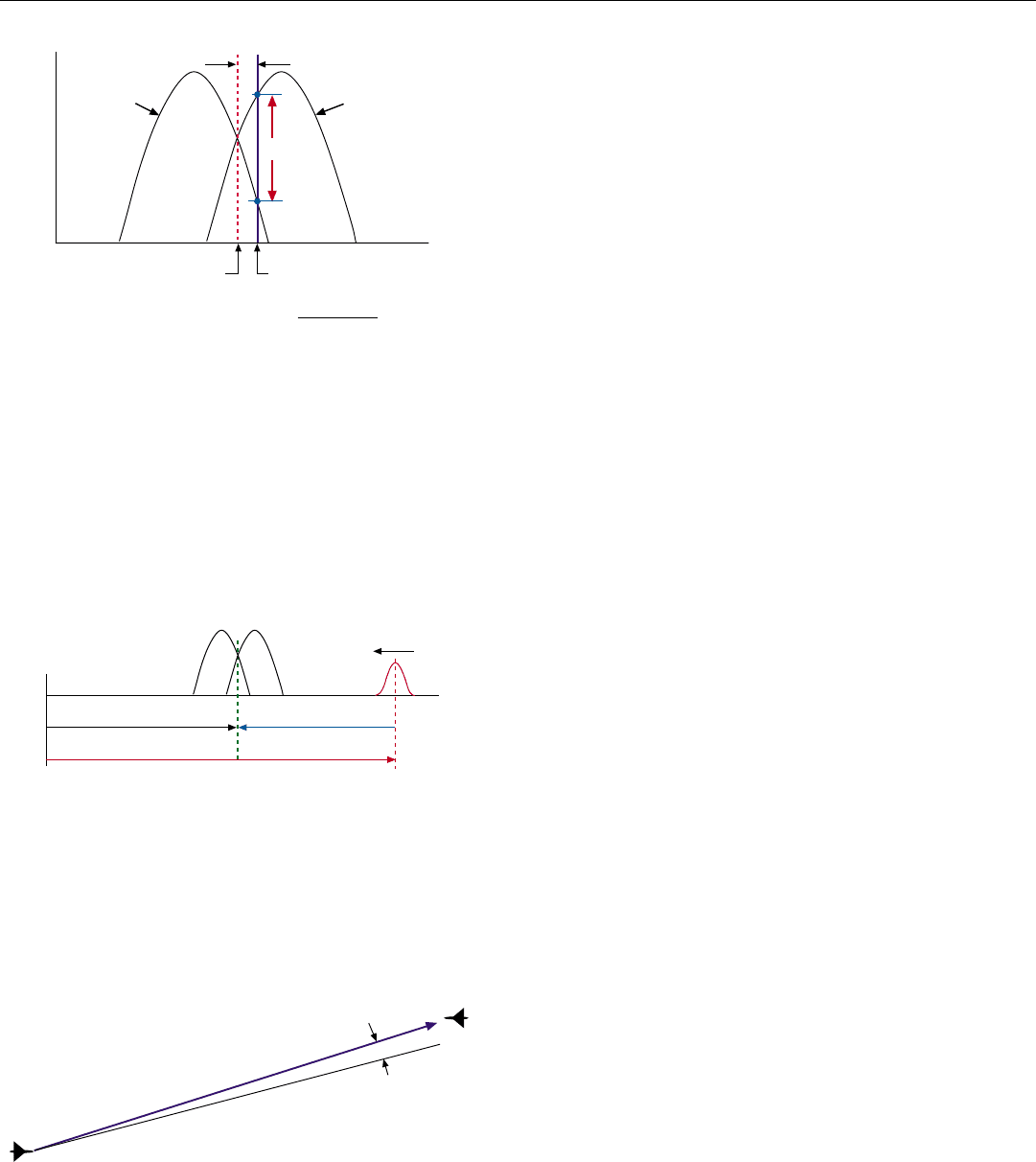
The simplest velocity gate is the crossover point of two
adjacent doppler filters,
2
called the low- and high-frequen-
cy filters. Any error in the alignment of the velocity gate, of
course, shows up as a difference between the outputs of
these filters. The discriminant is formed by taking the dif-
ference between the magnitudes of the outputs, V
H
– V
L
,
and normalizing it by dividing by their sum (Fig. 9). The
result is supplied to the velocity filter.
The functions of this filter almost exactly parallel those
of the range filter. The velocity filter’s outputs are simply
more accurate estimates of the target’s range rate and range
acceleration.
Based on the velocity filter’s most current range-rate and
range acceleration estimates, a velocity-gate command is
produced. It is essentially a prediction of what the target’s
doppler frequency will be when the next set of doppler fil-
ters is formed.
The command is applied to a variable-frequency RF
oscillator. Its output is mixed with the received signal,
thereby shifting its frequency so that the target’s predicted
doppler frequency will be centered in the velocity gate.
The sum of the oscillator’s frequency and the velocity gate’s
fixed frequency then is the target’s predicted doppler fre-
quency (Fig. 10).
3
Angle-Tracking Loop. The role of this loop is to (a) accu-
rately determine the target’s direction (angle) relative to a
chosen coordinate system, (b) determine the target’s angle
rate, and (c) keep the antenna boresight precisely trained
on the target. Commonly used coordinate systems are
defined in the panel on the facing page.
What the angle tracking loop measures is the angle
between the antenna boresight and the line of sight to the
target. This angle, ε, is called the angle off boresight, AOB
(Fig. 11), and is generally resolved into azimuth and eleva-
tion coordinates.
Previous chapters introduced three techniques for sens-
ing the AOB: sequential lobing, amplitude-comparison
monopulse, and phase-comparison monopulse. Since
they’re basically quite similar, we’ll consider only one here:
amplitude-comparison monopulse. For it, you’ll recall, dur-
ing reception, the antenna’s radiation pattern is split into
two lobes which cross at their half power points.
3. If the PRF is less than the tar-
get’s doppler frequency, some
multiple, n, of the PRF must
be added to this sum. See
Chap. 21, page 286.
2. Two separate banks of filters
are formed by integrating the
samples collected in the early
and late range bins. The
velocity gate may be formed
in either or both of them.
High
Frequency
Filter
Low
Frequency
Filter
Target Return
Doppler Frequency
Velocity Gate
V
L
V
H
∆V
Tracking Error
Velocity Discriminant =
V
H
– V
L
V
H
+ V
L
ε
Voltage
9. The simplest velocity gate is the intersection of two adjacent
doppler filters. The velocity discriminant is the difference
between the output voltage the target return produces from the
two filters divided by the sum of the two voltages.
AOB
Line of Sight to Target
Antenna Boresight
ε
11. What the angle tracking loop measures is the angle, AOB,
between the line of sight to the target and the antenna bore-
sight line.
Oscillator
Frequency
Target’s Predicted Doppler Frequency
Velocity Gate
Gate’s
Frequency
Target
0
10. When the oscillator has moved the target into the gate, the
sum of the oscillator’s frequency and the velocity gate’s fixed
frequency is the target’s predicted doppler frequency.
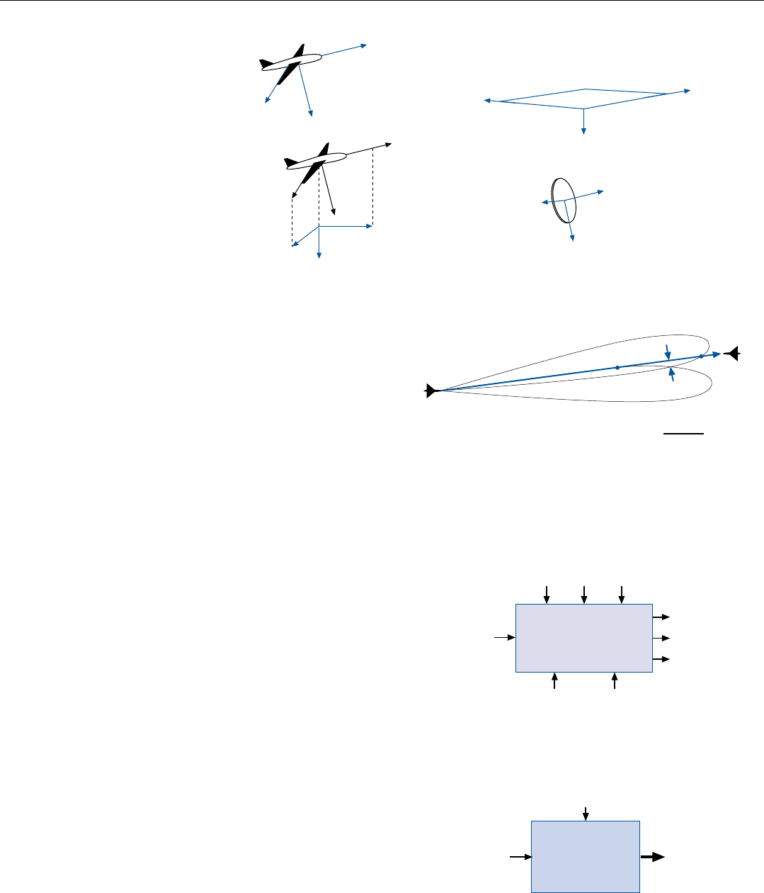
As can be seen from Fig. 12, the difference between the
amplitude of the target’s echoes as received through the left
and right lobes, V
L
– V
R
, is roughly proportional to the
AOB. Dividing this difference by the sum of the two ampli-
tudes yields a dimensionless discriminant for the azimuth
component of the AOB. A discriminant for the elevation
component is similarly formed.
The measured components of the AOB are supplied to
the angle-tracking filter along with the following environ-
mental information:
• Signal-to-noise ratio
• Radar-bearing aircraft’s velocity
• Target range and range rate
• Antenna’s current angle rate
From these inputs, the filter produces best estimates of
the azimuth and elevation components of the AOB, the
angle rate of the line of sight to the the target, and the tar-
get’s acceleration (Fig. 13).
To reduce the AOB and keep the antenna boresight
trained on the target, azimuth and elevation rate commands
are generated. Each of these is the algebraic sum of (a) the
filter’s best estimate of the respective line-of-sight rate and
(b) a rate proportional to the filter’s best estimate of the
respective component of the AOB.
The rate commands are fed to the antenna stabilization
system (Fig. 14). There they control the rate of precession
of gyros that inertially establish azimuth and elevation axes
in space to which the antenna is tightly slaved.
In the case of an electronically steered antenna, steering
commands for both angle tracking and space stabilization
must be provided. To continuously correct for changes in
aircraft attitude, no matter how small, new commands must
be computed and fed to the antenna at a very high rate.
CHAPTER 29 Automatic Tracking
387
COMMON
COORDINATE
SYSTEMS
Measurements of
distances and angles
make sense only if
referenced to a
coordinate system.
Several common
systems are shown here.
Antenna
Stabilized
Aircraft
i
s
k
s
j
s
Fixed, Nonrotating
(May be used for short time periods.)
i
j
k
(Tail to nose)
(Top to bottom)
(Right wing,
root to tip)
Aircraft
N = north
E = east
D = down
r = range
e = east
d
= down
r
e
d
N
E
D
V
R
V
L
AOB
Left Lobe
Right Lobe
AOB =
V
L
– V
R
V
L
+ V
R
ANGLE DISCRIMINANT
12. Angle-tracking discriminant for amplitude comparison
monopulse. The antenna lobes cross on the boresight line; so
the angle AOB is roughly proportional to the difference
between the voltage of returns received through the two lobes.
Acceleration*
Angular Rate*
AOB*
Az. & El.
AOB
Estimates
Aircraft
Velocity
* Az & El Components,
best estimate.
Antenna
Motion
TARGET
Angle-Tracking
Filter
Range
Rate
SNRRange
Antenna
Stabilization
System
Aircraft
Motion
Achieved
Boresight
Angular Rate
Azimuth &
Elevation Rate
Commands
13. Inputs and outputs of the angle-tracking filter.
14. The antenna is stabilized against changes in aircraft attitude
by slaving it to azimuth and elevation axes established by
rate-integrating gyros mounted on it. The rate commands pre-
cess the gyros.
PART VI Air-to-Air Operation
388
Track-While-Scan
Track-while-scan (TWS) is an elegant combination of
searching and tracking. To search for targets, the radar
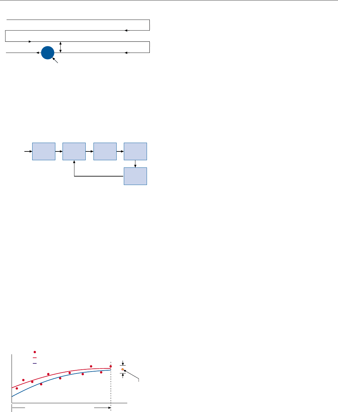
repeatedly scans a raster of one or more bars (Fig. 15). Each
scan is independent of all the others. Whenever a target is
detected, the radar typically provides both the operator and
the TWS function with estimates of the target’s range, range
rate (doppler), azimuth angle, and elevation angle. For any
one detection the estimates are referred to collectively as an
observation.
In pure search, the operator must decide whether targets
detected on the current scan are the same as those detected
on a previous scan or scans. With TWS, however, this deci-
sion must be made automatically. The algorithm used to
make it is one of the most complex algorithms in the radar.
In the course of successive scans, TWS maintains an
accurate track of the relative flight path of each valid target.
This process is iteratively carried out in five basic steps:
preprocessing, correlation, track initiation and deletion, fil-
tering, and gate formation (Fig. 16).
Preprocessing. In this step, two important operations
may be performed on each new observation. First, if a tar-
get having the same range, range rate, and angular position
has been detected on a preceding, overlapping bar of the
scan, the observations are combined. Second, if not already
so referenced, each observation is translated to a fixed coor-
dinate system, such as the NED. The angle estimates are
conveniently formulated as direction cosines—cosines of
the angles between the direction of the target and the N, E,
and D axes. Range and range rate may be projected onto
the N, E, and D axes simply by multiplying them by the
respective direction cosines.
Correlation. The purpose of this step is to determine
whether a new observation should be assigned to an exist-
ing track. On the basis of the observations assigned to the
track thus far, tracking filters accurately extend the values
of the N, E, and D components of each parameter of the
track to the time of the current observation. The filters then
predict what the values of these components will be at the
time of the next observation.
On the basis of accuracy statistics derived by the filters, a
gate scaled to the maximum error in measurement and pre-
diction is placed around each component of the prediction
for the track, as illustrated in Fig. 17. If the next observa-
tion falls within all of the gates for the track, the observa-
tion is assigned to the track.
Naturally, when closely spaced observations are received,
conflicts in assignments are likely to occur. To facilitate
3 dB beamwidth
< 3 dB beamwidth
Start
Finish
15. A representative four-bar raster scan. So that targets won’t be
missed, spacing of bars is less than the 3-dB beamwidth.
Consequently, the same target may often be detected on more
than one bar—one of several conflicts TWS resolves.
New
Obser-
vations
Updated Gates
Correlate
with
Tracks
Initiate or
Delete
Tracks
Filter
Form
Gates
Pre-
process
16. The five basic steps in track-while-scan processing.
Distance on Coordinate
Gate
Predicted
Position,
Next
Observation
Time since initial observation
Target Observation
Computed Track
Actual Track
17. Representative track of one component (N, E, or D) of one of
a target’s parameters, illustrating its predicted value at the
time of the next observation and the gate for correlating the
observation with the track.
their resolution, a statistical distance of each observation
from the track or tracks involved is computed by normaliz-
ing and combining the differences between measurement
and prediction for all components of the observation. Each
track is centered in a gate, the radius of which corresponds
to the maximum possible statistical distance between mea-
surement and prediction.
CHAPTER 29 Automatic Tracking
389
4. A restriction applied in this
case is that a tentative track
cannot be initiated for an
observation that falls within
the gate of an existing track.
Accordingly, because a com-
peting observation is assigned
to the track O
3
falls in, O
3
is
discarded.
d
i, j
T
i
O
j
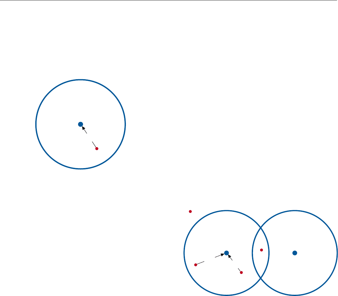
18. Gate for correlating an observation, O
j
, with a track, T
i
. Size
of the gate corresponds to the maximum possible statistical
distance, d, a valid observation may be from the track.
A representative conflict is illustrated in Fig. 19.
Observation O
1
falls within the gates of two different tracks:
T
1
and T
2
. Observations O
2
and O
3
both fall within the gate
of track T
2
. Conflicts such as this are typically resolved as
follows.
• Observation O
1
is assigned to track T
1
because it is
the only observation within the gate of T
1
, while T
2
has other observations, O
2
and O
3
, within its gate.
• Observation O
2
is assigned to track T
2
because its dis-
tance, d
2,2
, from the center of the gate is less than that
of O
3
.
4
Track Creation or Deletion. When a new observation,
such as O
4
in Fig. 19 does not fit in the gate of an existing
track, a tentative new track is established. If, on the next
scan (or possibly the next scan after that) a second observa-
tion correlates with this track, the track is confirmed. If not,
the observation is assumed to have been a false alarm and is
dropped. Similarly, if for a given number of scans no new
observation correlates with an existing track, the track is
deleted.
Filtering. This is similar to the filtering performed in sin-
gle-target tracking. On the basis of the differences between
the predictions and new measurements for each track, the
track is updated, new predictions are made, and accuracy
statistics for both observations and predictions are derived.
O
3
O
2
d
2,3
d
2,2
O
4
T
2
T
1
O
1
19. Typical conflicts arising when targets are closely spaced.
Here, gates for tracks T
2
and T
1
overlap. Observation O
1
falls in both gates, and observations O
2
and O
3
both fall in
the gate for track T
2
.
PART VI Air-to-Air Operation
390
Gate Formation. From the prediction and accuracy sta-
tistics derived by the filter, new gates are formed and sup-
plied to the correlation function.
As a result of the filtering, the longer a target is observed,
the more accurately the new gates are positioned, and the
closer the computed track comes to the actual track.
Summary
For single-target tracking, semi-independent tracking
loops are generally provided for range, doppler frequency,
azimuth, and elevation. Each loop includes four basic func-
tions: measurement, filtering, control, and system response.
The range-tracking error is measured by taking the dif-
ference between early and late samples of the target echoes;
the doppler-tracking error, by taking the difference between
the outputs of two adjacent doppler filters; the angle-track-
ing errors, by taking the difference between the returns
received through two antenna lobes.
The “scale factor” of each measurement, commonly rep-
resented by a plot of the measured value of the tracking
error versus the true value is called a discriminant. So that
the measurement will be largely independent of signal
strength and precise measurement of voltages or powers
won’t be required, the discriminant is normalized.
Successive measurements are, in effect, passed through a
low-pass filter whose gain and cut-off frequency are con-
stantly adjusted in light of the SNR, potential target maneu-
vers, and the aircraft’s own maneuvers to eliminate as much
noise as possible without introducing excessive lag.
From the filter outputs, a command calculated to reduce
the tracking error to zero is produced. For range tracking,
the command adjusts the radar’s sampling times; for
doppler tracking, it shifts the frequency of the received
echoes; for angle tracking it precesses the rate gyros of the
antenna stabilization system.
In track-while-scan, targets detected in successive search
scans are accurately tracked by filtering their parameters,
much as in single-target tracking. For each track, gates
based on the filtered parameters are used to determine
whether new detections should be assigned to existing
tracks or tentative tracks should be established for them,
and whether any existing tracks should be dropped.
Measure Filter Control
Respond
Actual
Value of
Parameter
Radar’s Knowlege of
Parameter
Tracking
Error
Time
R
E
Stretched Envelope
of Target Echo
Sampling
Times
R
L
= Magnitude of sample in late range bin
R
E
= Magnitude of sample in early range bin
e = Tracking error
R
L
e
Range Gate
e ∝ R
L
– R
E
New
Obser-
vations
Updated Gates
Correlate
with
Tracks
Initiate or
Delete
Tracks
Filter
Form
Gates
Pre-
process
Time
Range
Gate
Time Until Arrival
of Next Echo
Transmitted
Pulse
393
Meeting High
Resolution Ground
Mapping Requirements
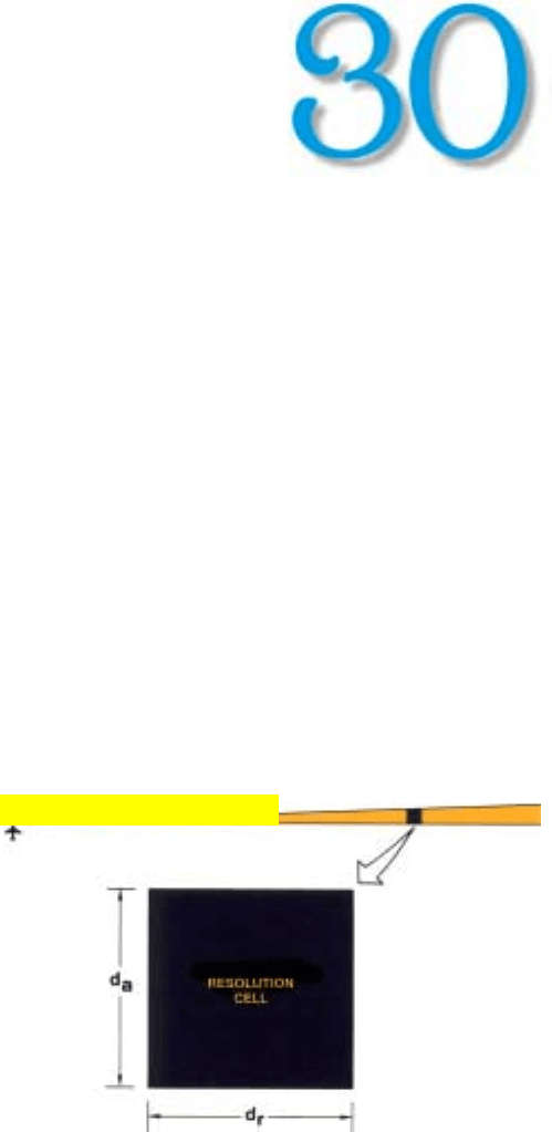
1. Resolution distance is the minimum distance two points on
the ground can be separated and still be discerned sepa-
rately. A resolution cell is a rectangle whose sides are the
range and azimuth resolution distances.
A
n increasingly important airborne radar applica-
tion is making radar maps of sufficiently
fine
resolution that topographic features and objects
on the ground can be recognized.
In this chapter, we will learn how ground map resolution
is defined and see what the optimum resolution is for vari-
ous uses; then, review the approaches taken to providing it.
How Resolution Is Defined
The quality of the ground maps produced by a radar is
gauged primarily by the ability of the radar to resolve closely
spaced features of the terrain. This ability is generally
defined in terms of resolution distance and cell size.
Resolution distance is the minimum distance by which
two points on the ground may be separated and still be dis-
cerned individually by the radar. The separation is usually
expressed in terms of a range component, d
r
, and an
azimuth or cross range component, d
a
—the component at
right angles to the line of sight from the radar.
A resolution cell, or “pixel” (for picture element),
1
is a
rectangle whose sides are d
r
and d
a
(Fig. 1). Because fea-
tures of the terrain may be oriented in any direction, ideally
d
r
and d
a
are equal, making the cell a square.
As a rule, however, one does not deliberately restrict the
resolution in one direction to make the cells square. In real-
beam mapping for instance, where fine azimuth resolution
is difficult to obtain, d
r
is typically a small fraction of d
a
(see
Fig. 7). Nor is the resolution cell a sharply delineated rec-
tangle, as shown in Fig. 1. Rather, it is usually a rounded
rectangular “blob” whose brightness falls off at the edges.
1. Pixel and resolution cell are
not exactly synonymous.
Their dimensions may differ
considerably depending
upon how the radar’s signal
processor and display are
mechanized.
Click for high-quality image
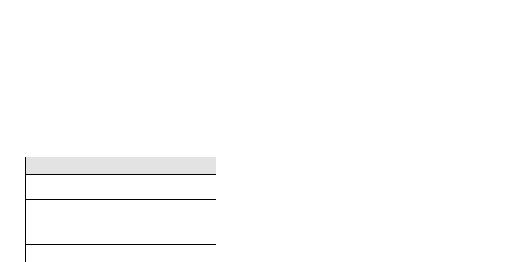
RESOLUTION REQUIRED FOR
VARIOUS MAPPING APPLICATIONS
Features to be Resolved Cell size
Coast lines, large cities, and the
500 ft
outlines of mountains
Major highways, variations in fields 60–100 ft
“Road map” details: city streets,
30–50 ft
large buildings, small airfields
Vehicles, houses, small buildings 5–10 ft
PART VII High Resolution Ground Mapping and Imaging
394
Factors Influencing Choice of Cell Size
Among the more important considerations influencing
the choice of cell size are the sizes of the objects that must
be resolved, the amount of signal processing required to
produce the maps, cost, and finally the task of interpreting
the maps once they have ben made.
Size of Objects to Be Resolved. How large the resolution
cells can be and still provide useful ground maps depends
upon what the maps are used for. For discerning gross fea-
tures of the terrain such as coastlines and the outlines of
cities and mountains, a resolution of 500 feet or so will do.
For recognizing major highways, variations in the texture of
fields, and the like, a resolution of around 100 feet is need-
ed. To recognize city streets, large buildings, and small air-
fields—the sort of details commonly included in a road
map—resolution on the order of 30 to 50 feet is required.
To recognize the shapes of objects on the ground—such
as vehicles, houses, and small buildings—the resolution
must be considerably finer. Exactly how fine varies with
both the sizes and the shapes of the objects. As a rule, the
required resolution distance is somewhere between 1/5th
and 1/20th of the major dimension of the smallest object to
be recognized.
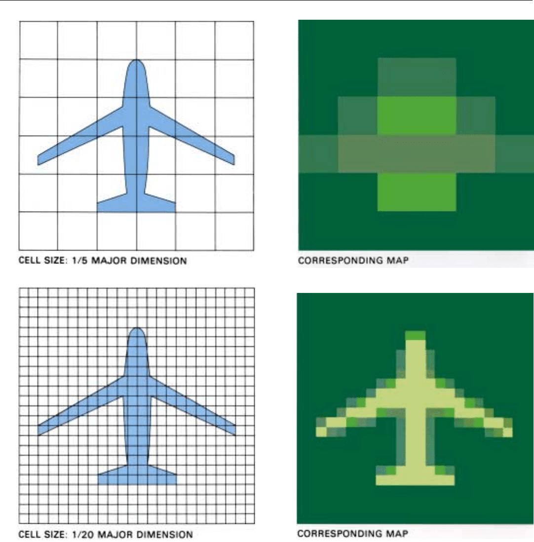
This is illustrated in Fig. 2 (facing page). It shows two
silhouettes of the same airplane. Over one is superimposed
a grid of resolution cells whose sides are 1/5th of the
wingspan. Over the other is superimposed a grid of cells
whose sides are 1/20th of the wingspan.
Alongside each silhouette is a simplified representation
of the ground map corresponding to the indicated cell size.
In these maps, cells that are filled completely by the silhou-
ette are shown as yellow; cells that are partly filled are
shown in shades of green corresponding to the percentage
filled; cells that do not include the airplane at all are shown
as dark green. For this particular shape, a resolution of
1/5th of the major dimension enables some shape recogni-
tion, while a resolution of 1/20th of this dimension enables
good recognition.
It should be pointed out, though, that in preparing Fig.
2 all elements of the airplane were assumed to reflect radio
waves in the radar’s direction equally. Actually, for any one
combination of look angle, radio frequency, and polariza-
tion, only a few bright scattering centers might be map-
pable. So even though the cell size was only 1/20th of the
major dimension, the airplane’s shape might still be difficult
to recognize. However, as we shall see, by repeatedly map-
ping the same area from different directions and with differ-
ent radio frequencies and polarizations, we can substantial-
ly increase the fraction of an object’s surface from which
mappable reflections are received. Through such tech-
niques, we can come quite close to realizing the kind of
shape recognition illustrated in Fig. 2 (above).
Amount of Signal Processing Required. A major con-
straint on the fineness of resolution that one would like to
provide is the amount of signal processing it requires.
CHAPTER 30 Meeting High Resolution Ground Mapping Requirements
395
2. Cell size required for shape resolution. Silhouettes (left) are identical. Radar maps, right, are simplified representations. Assuming that
all elements of the plane reflect equally in the radar’s direction, a cell size of 1/20 of the silhouette’s major dimension enables good
shape recognition.
