George W. Stimson introduction to Airborne Radar (Se)
Подождите немного. Документ загружается.

CHAPTER 31 Principles of Synthetic Array Aperture Radar
407
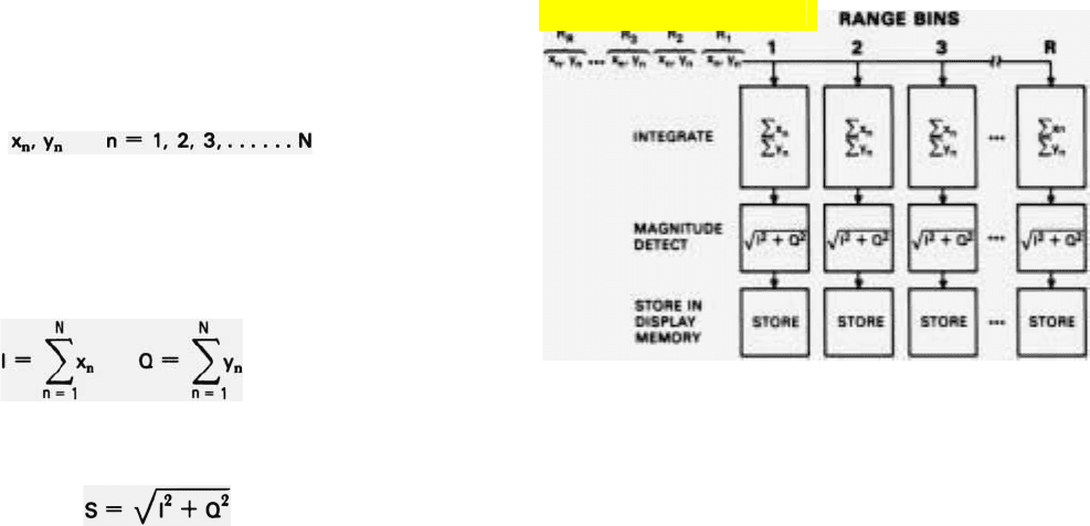
Signal Processing Required. In the foregoing discussion,
the inputs to the SAR processor were referred to only as the
digitized radar returns. In an actual radar, the inputs would
be the digitized I and Q components (x
n
, y
n
) of the returns
(translated to video frequencies). The sums that build up in
the range bins, then, would be the vector sums of the accu-
mulated values of x
n
and y
n
. And the quantities transferred
from the range bins to the display memory would be the
magnitudes of the vector sums. The signal processing
required to synthesize a simple array of this sort is summa-
rized in the panel at the top of the page. Note that the
equations shown there are identical to those which must be
solved to form a doppler filter tuned to zero frequency (or
to the PRF).
Limitation of Unfocused Array. The rudimentary array
just described is called an “unfocused” array. For it must be
short enough in relation to the range to the swath being
mapped that the lines of sight from any one point at the
swath’s range to the individual array elements are essentially
parallel. In this respect, the array is similar to a pinhole
camera: both are focused at infinity.
Now, if the array length is an appreciable fraction of the
swath’s range, the lines of sight from a point at that range to
the individual elements will diverge slightly. Then, even if
the point is on the boresight line, the distances to the ele-
SIGNAL PROCESSING FOR UNFOCUSED ARRAY
The signal processing required to synthesize an unfocused
array antenna can be summarized mathematically as follows:
Inputs: For each resolvable range (R
r
), N successive pairs of
numbers are supplied.
Each pair represents the I and Q components of the return,
received from range R
r
by a single array element.
Integration: To form the beam (azimuth processing), the I and
Q components are summed.
Magnitude Detection: The magnitude or the vector sum of
l and Q is computed and output.
S is the amplitude of the total return from a single-resolution
ceII on the boresight line at range R
r
.
(An intermediate step not shown in the above diagram is
the scaling of the detected magnitudes to the values of
intensity—gray levels—that are to be displayed.)
Click for high-quality image
PART VII High Resolution Ground Mapping and Imaging
408
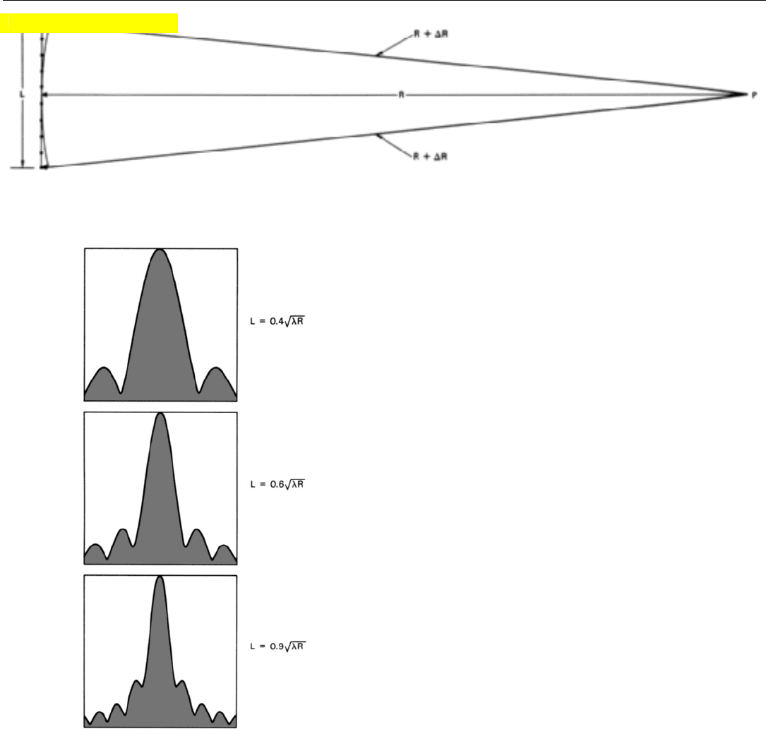
ments will not all be the same (Fig. 8, above). Since the
wavelength is generally fairly short, very small differences
in these distances can result in considerable differences in
the phases of the returns which the individual array ele-
ments receive from the point.
Because these phase errors are not compensated in the
unfocused array, its capabilities are quite limited. While the
azimuth resolution distance the array provides at any given
range can initially be reduced by increasing the length of
the array, a point is soon reached beyond which any further
increase in length only degrades performance.
Degradation begins with a gradual increase in gain of the
sidelobes relative to the mainlobe and a merging of the
lower order sidelobes with the mainlobe (Fig. 9).
This effect continues increasingly and is accompanied by
a progressive fall-off in the rate at which the mainlobe gain
increases with array length.
The reason for the fall-off in gain can be seen if we exam-
ine Fig. 8 again. It shows the distance from point P on the
boresight line to each element of an array of length L. For
elements near the array center, there is very little difference
in this distance. But for elements farther and farther
removed from the center, the difference grows increasingly.
As the array is lengthened, therefore, the phase of the
returns received by the end-most elements falls increasingly
far behind the phase of the sum of the returns received by
the other elements.
This progressive phase rotation and its effect on the
mainlobe gain of the synthetic array is illustrated in Fig. 10
(top of facing page). The phasors shown there represent the
returns received by the individual elements of a 27-element
array from a distant point (P) on the boresight line. The
phase of the return received by the middle element (14) is
taken as the reference. The gain in the boresight direction
corresponds to the sum of the phasors.
The returns received by the central elements (9 through
19) are so close to being in phase that their sum is virtually
undegraded by the lack of focus. But the phases of the
returns received by elements farther and farther out are
8. Distance from a point (P) on the boresight line of an array antenna to the individual array elements. If array length (L) is an appreciable frac-
tion of the range (R), the distances to the end elements will be appreciably greater than the distances in the central element.
9. Radiation pattern of an unfocused synthetic array showing
increase in relative gain of sidelobes and merging of side-
lobes with mainlobe as array length (L) is increased.
Click for high-quality image
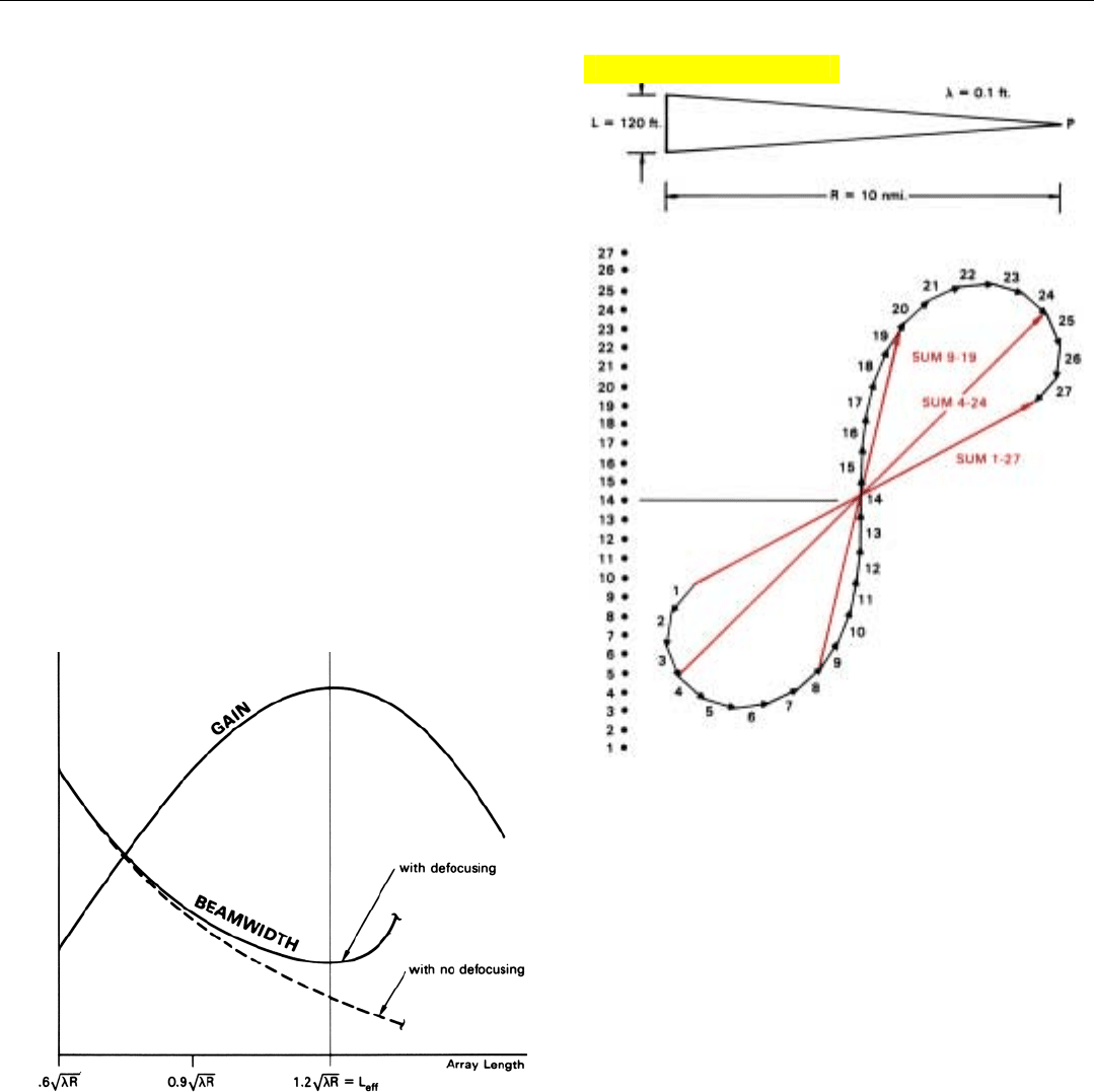
rotated increasingly. The returns received by elements 4 and
24 are nearly 90˚ out of phase with the sum of the returns
received by the elements closer in, hence, contribute only
negligibly to that sum. The returns received by elements 1,
2, and 3 and 25, 26, and 27 are actually subtractive.
Obviously, under the conditions for which Fig. 10 was
drawn, the gain would have its maximum value if the array
were only 21 elements long (elements 4 through 24).
The degradation of beamwidth closely parallels that of
mainlobe gain. Initially, the gain at angles slightly off bore-
sight is degraded by the lack of focus to nearly the same
extent as the gain in the boresight direction. So at first,
there is little reduction in the rate at which the beam nar-
rows as the array is lengthened. But when the length reach-
es the point where the gain in the boresight direction stops
increasing, the beamwidth stops decreasing. If we lengthen
the array beyond this point, the beam starts spreading.
From the standpoint of both gain and beamwidth, the max-
imum effective length has been reached.
In Fig. 11, the gain and beamwidth for an unfocused
array are plotted versus array length.
11. Effect of increased array length on gain and beamwidth of an
unfocused synthetic array. Gain is maximum and beamwidth
is minimum when length, L = 1.2
公
僓
λR.
CHAPTER 31 Principles of Synthetic Array Aperture Radar
409
10. Degradation in the gain of an unfocused array. Phasors repre-
sent returns received from a distant point P by individual array
elements. Gain is the sum of the phasors. In this case, the gain
could be increased by decreasing the length of the array.
It can be shown from the geometry of the situation that
the array length for which given values of gain and
beamwidth are obtained varies in proportion to 公
僓
λR ,
where
λ is the wavelength and R is the range. To make the
graph of Fig. 11 applicable to any combination of
λ and R,
the array length is plotted there in terms of 公
僓
λR. As you
can see, the maximum effective array length is
L
eff
= 1.2 λR.
Click for high-quality image
PART VII High Resolution Ground Mapping and Imaging
410
Another way of looking at the effects of defocusing is
this. Imagine that you are approaching an unfocused array
of a given length from a long enough distance that the lines
of sight to each “elements” of the array are essentially paral-
lel. The beamwidth of the array at your range, therefore,
does not change as you advance.
However, as you approach the range for which the array
length is optimum and defocusing comes into play, the
beamwidth starts increasing.
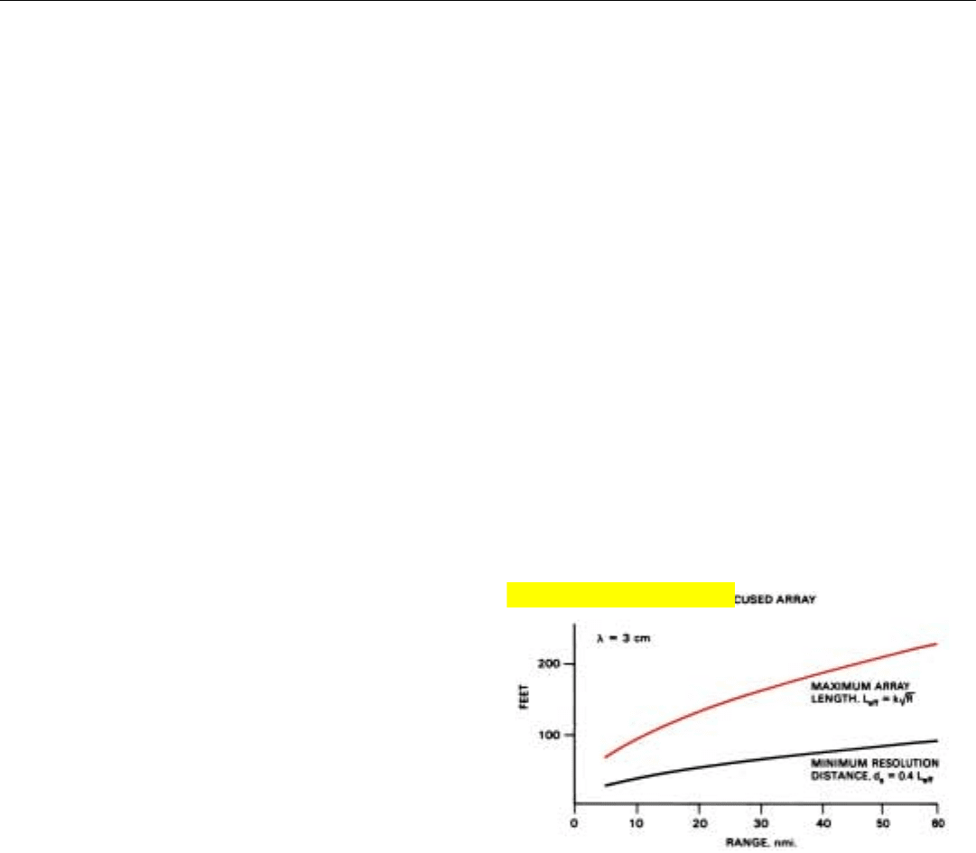
The azimuth resolution distance, hence the finest achiev-
able resolution at that range, turns out to be roughly 40
percent of the array length.
d
a
min
=
~
0.4 L
eff
Moreover, beyond that range, we cannot make the
azimuth resolution of the radar independent of range, as we
would like. For when we lengthen the array further, the res-
olution distance increases as the square root of the range
(Fig. 12).
12. Maximum effective length of unfocused array increases only as
square root of range. Resolution distance at range for which
length is optimized is roughly 40 percent of array length.
Focused Array
The limitation on array length may largely be removed
by focusing the array. Then, by suitably increasing the
length of the array in proportion to the range, virtually the
same resolution may be obtained at any desired range.
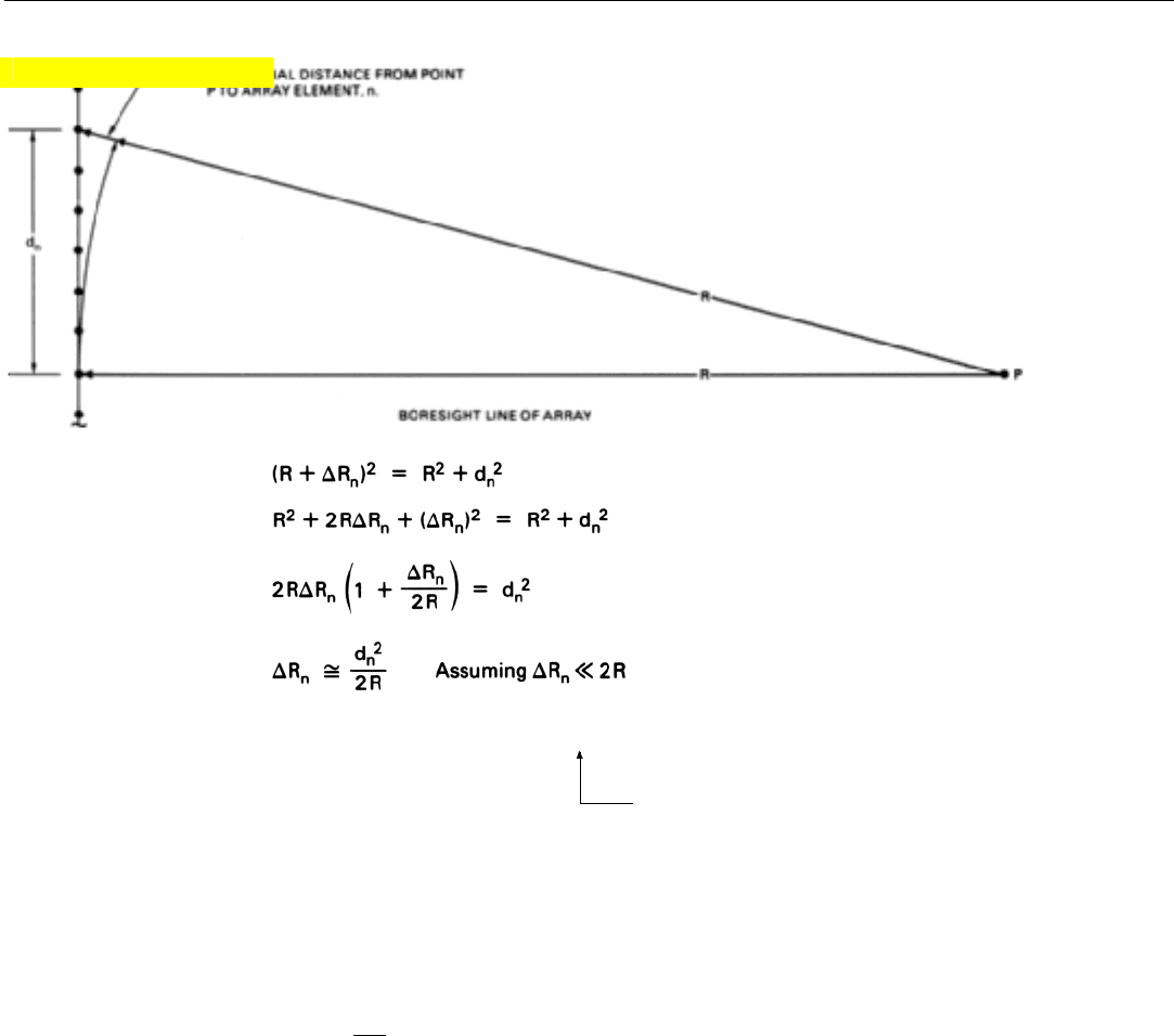
How Focusing Is Done. In principle, to focus an array all
you need to do is apply an appropriate phase correction
(rotation) to the returns received by each array element. As
illustrated in Fig. 13 (top of facing page), the phase error
for any one element, hence the phase rotation needed to
cancel the error, is proportional to the square of the dis-
Click for high-quality image
∴ PHASE ERROR,
φ
n
=
____
2π
(2∆R
n
) ≈
____
2π
(
____
d
n
2
)
Radians
λλR
Accounts for Round-Trip Travel
CHAPTER 31 Principles of Synthetic Array Aperture Radar
411
tance of the element from the center of the array.
Phase correction = –
2π
d
n
2
λR
where
d
n
= distance of element n from array center
λ = wavelength (same units as d
n
)
R = range to area being mapped (same units as λ)
In some cases, it may be possible to presum the returns
received by blocks of adjacent elements without impairing
performance. By rotating only the phases of the sums, com-
puting and storage requirements may be eased.
To simplify the description, however, we will omit presum-
ming here. Also, we will assume that the combination of array
length, PRF, and range is such that the resolution distance,
d
a
, is roughly equal to the spacing between array elements.
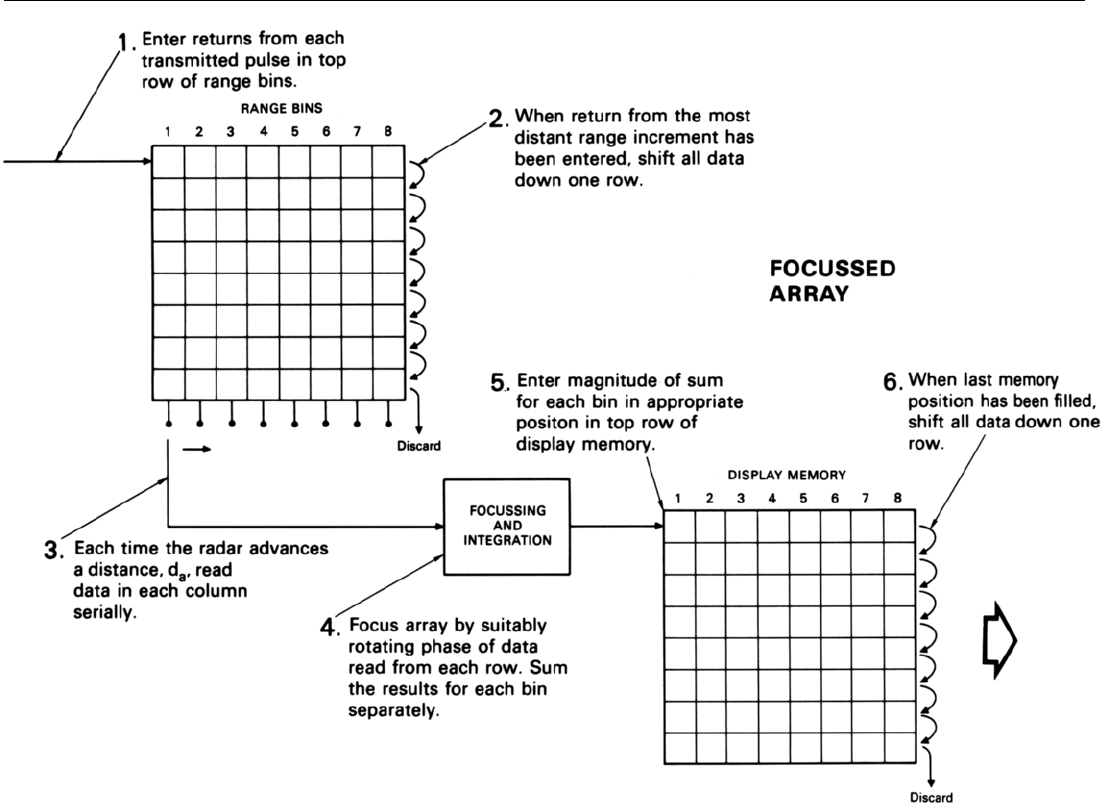
To focus an array when no presumming is done, we must
provide as many rows of storage positions in the bank of
13. Phase error for return received by any one array element (n) is proportional to the square of the distance (d
n
) from the element to the array
center. Factor of two by which ∆R
n
is multiplied accounts for the phase error being proportional to the difference in
round-trip
distance from
the element to point P (see page 416).
Click for high-quality image
PART VII High Resolution Ground Mapping and Imaging
412
14. How array is focused in a line-by-line processor. To simplify the description, conditions are assumed to be such that the resolution distance,
d
a
, equals the spacing between array elements. Hence, every time a pulse is transmitted a new array must by synthesized.
range bins as there are array elements (Fig. 14, above). As
the returns from any one transmitted pulse (array element)
come in, they are stored in the top row. When the return
from the most distant range increment has been received,
the contents of every row are shifted down to the row
below it to make room for the incoming returns from the
next transmitted pulse. The contents of the bottom row are
discarded.
Between these shifts, the column of numbers in each bin
is read serially and the numbers are appropriately phase
shifted and summed—a process called azimuth compression.
The magnitude of the sum for each range bin is entered in
the appropriate range positions in the top row of the dis-
play memory. Thus (for the conditions assumed in this
example), every time the returns from another transmitted
pulse have been received—i.e., every time the radar has
advanced a distance equal to the spacing between array ele-
ments—another array is synthesized.
3
3. If the resolution distance, d
a
were greater than the spacing
between array elements, an
array would be synthesized
only after the radar had
advanced a distance d
a
.
CHAPTER 31 Principles of Synthetic Array Aperture Radar
413
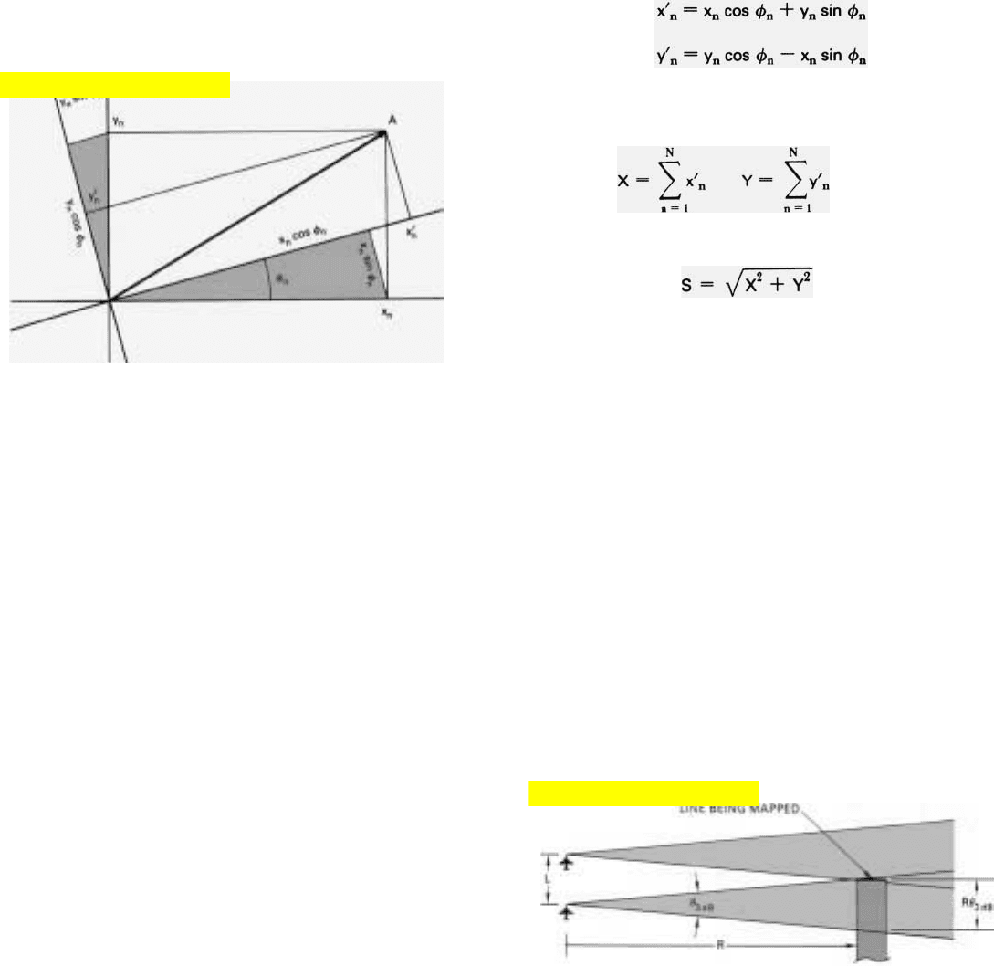
Signal Processing Required. The computations (per
range bin) required to perform the phase rotation and sum-
ming for a focused array are shown in the panel, above.
They are exactly the same, you will notice, as the computa-
tions required to form a doppler filter with the DFT.
Azimuth Resolution. With focusing, the length of the
array can be greatly increased. But as with all things, a point
is ultimately reached where a further increase in length does
not improve resolution. In the case of an array whose
azimuth angle is fixed—that is, one which looks out at a
constant angle relative to the flight path—this limit is estab-
lished by the physical size of the elemental radiator, the real
antenna. Surprisingly, the smaller this antenna is, the longer
the array can be made.
The reason is simple enough. For return to be received
from any one ground patch by all elements of the array, the
beam of the real antenna must be wide enough for the
patch to fall within the beam for every position of the
antenna in the entire length of the array (Fig. 15). For that
condition to be satisfied, the width of the beam at the range
of the patch must at least equal the length of the array. The
smaller the real antenna is, the wider its beam; hence, the
longer the array can be made and the finer the resolution
that can be achieved.
For a given real-antenna size, how fine can that be?
Before answering this question, we must consider an impor-
15. Each line that is mapped must be within the mainlobe of the
real antenna while the radar traverses the entire length of the
array, L.
SIGNAL PROCESSING FOR A FOCUSED ARRAY
To focus an array, for every range bin the signal processor
must mathematically perform the equivalent of rotating the
phasor representation (A) of the return received by each
successive array element (n) through the phase angle,
n
(the
value of which was derived in Figure 13).
The I and Q components of the phasor before rotation are the
inputs, x
n
and y
n
After rotation, we’ll represent the components by
x⬘
n
and y⬘
n
To perform the rotation, the following algorithms must
be computed.
The values of x⬘
n
and y⬘
n
for the total number of array elements (N)
must then be summed separately
and the magnitude of the vector sum of x and y must be calculated.
These, you’ll recognize, are the same algorithms that are
computed when forming a digital filter with the DFT.
Click for high-quality image
Click for high-quality image
PART VII High Resolution Ground Mapping and Imaging
414
tant difference between the beam of a synthetic array and
the beam of a real array.
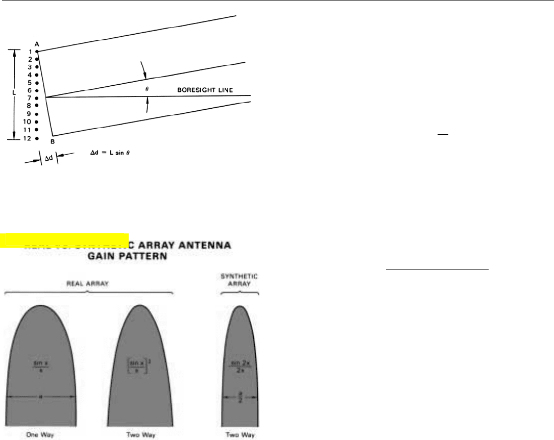
A real array has both a one-way and a two-way radiation
pattern. The one-way pattern is formed upon transmission
as a result of the progressive difference in the distances
from successive array elements to any point off the bore-
sight line (Fig. 16). (The phases of the radiation from the
individual elements arriving at that point differ in proportion
to the differences in distance.) This pattern has a sin x/x
shape. The two-way pattern is formed upon reception,
through the same mechanism. Since the phase shifts are the
same for both transmission and reception, the two-way
pattern is essentially a compounding of the one-way pat-
tern, and so has a (sin x/x)
2
shape.
A synthetic array, on the other hand, has only a two-way
pattern. For the array is synthesized out of the returns
received by the real antenna, which sequentially assumes
the role of successive array elements. Because each element
receives only the returns from its own transmissions, how-
ever, the element-to-element phase shifts in the returns
received from a given point off the boresight line correspond
to the differences in the round-trip distances from the indi-
vidual elements to the point and back (see panel, page 416).
This is equivalent to saying that the two-way pattern of the
synthetic array has the same shape as the one-way pattern of
a real array of twice the length, sin 2x / 2x (Fig. 17).
For a uniformly illuminated real array, the one-way 3-dB
beamwidth is 0.88 times the ratio of the wavelength to the
array length. Consequently, for a uniformly illuminated syn-
thetic array, the two-way 3-dB beamwidth is
θ
3 dB
= 0.44
λ
__
radians
L
The point on the radiation pattern where the beamwidth is
measured, of course, is fairly arbitrary. It turns out that by
measuring the beamwidth at a point 1 dB lower down, the
factor 0.44 can be increased to one half. To simplify the
beamwidth equation, therefore, the minus 4-dB point is
commonly used.
θ
4 dB
=
λ
___
radians
2L
The azimuth resolution distance, then is
d
a
=
λ
___
R
2L
Armed with this expression, we can now go back and
answer the question raised earlier: if the length of the syn-
thetic array is limited to the width of the beam of the real
16. One-way radiation pattern of a real array is formed during
transmission as a result of progressive difference in distance
from successive array elements to observation point.
17. Comparison of mainlobes of real and synthetic arrays of same
length. Synthetic array has no one-way radiation pattern since
the array is synthesized from the radar return.
Click for high-quality image
antenna at the range being mapped, for a given sized anten-
na how fine can the resolution of the synthetic array be?
If the real antenna is a linear array and its length is
l,
then its one-way 4-dB beamwidth is λ /
l, where l is the
array length. Multiplying this expression by the range, R, of
the swath being mapped gives the maximum length of the
real array.
L
max
=
λ
R
l
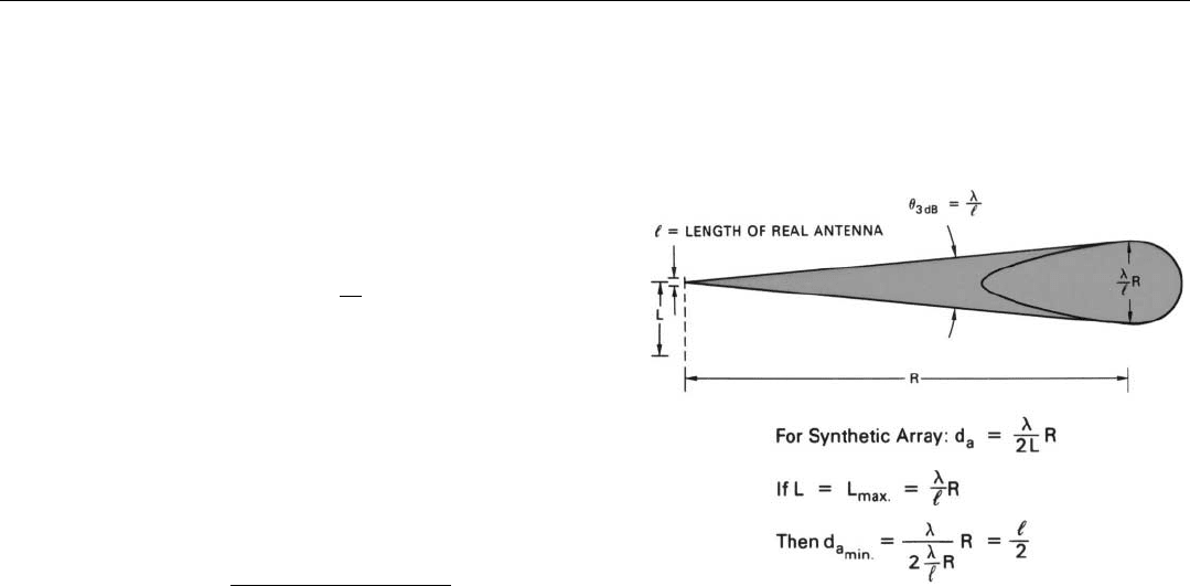
Substituting L
max
for L in the expression for azimuth
resolution distance (Fig. 18), we find that the minimum
resolution distance d
a
min
is half the length of the real
antenna.
d
a
min
=
Length of real antenna
2
This, then, is the ultimate resolution of a synthetic array
whose beam is positioned at a fixed angle relative to the
flight path, as in strip map radars. As we will see in the next
chapter, this limitation is removed in the “spotlight” mode,
by keeping the beam of the real antenna continuously
trained on the area being mapped.
Reducing the Computing Load: Doppler Processing
As is clear from Fig. 14 (page 412), if the array is very
long, an immense amount of computing is required for
line-by-line processing of a focused array. In the simple
example illustrated there, every time the radar transmits a
pulse, it must perform the phase correction all over again
for every pulse that has been received over an entire array
length and sum the results.
Put another way, if there are N elements in the array,
every time the radar advances a distance equal to the array
length, it must phase correct and sum (N x N) returns for
every range bin. This load may be reduced somewhat by
presumming (if conditions permit presumming). But it is
still formidable.
The computing load can, however, be dramatically
reduced by processing the data in parallel for many lines of
the map at one time, rather than serially, a line at a time.
For parallel processing, the returns from different
azimuth angles are isolated with doppler filters. But before
getting into the details of that, we must see how doppler
frequency is related to azimuth angle.
CHAPTER 31 Principles of Synthetic Array Aperture Radar
415
18. If array length, L, is made equal to beamwidth of real anten-
na at range, R, azimuth resolution of synthetic array will
equal 1/2 length of real antenna.
PART VII High Resolution Ground Mapping and Imaging
416
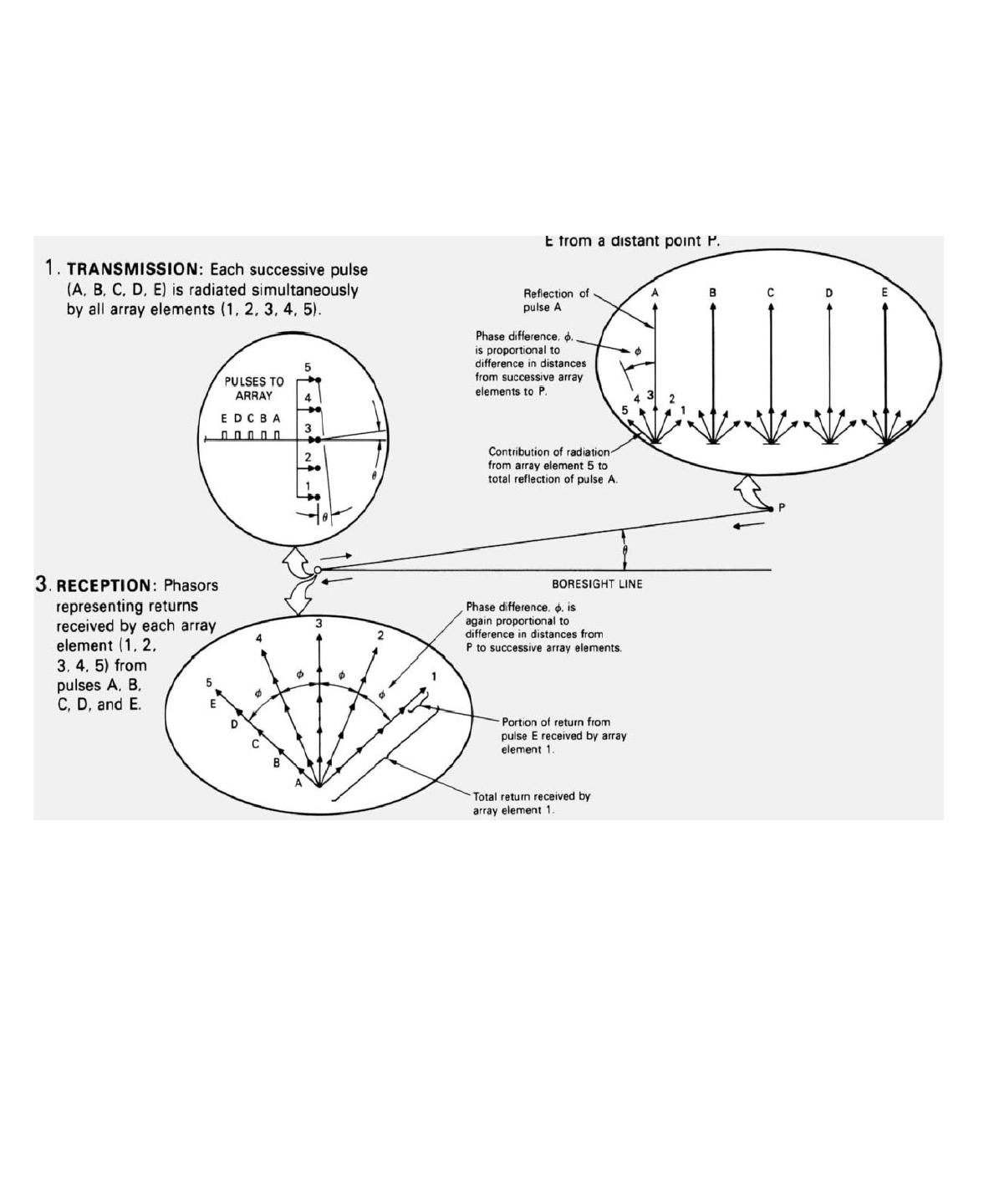
WHY THE ELEMENT-TO-ELEMENT PHASE SHIFT
IS DOUBLE IN A SYNTHETIC ARRAY
A linear-array radar antenna achieves its directivity by virtue of
the progressive shift in the phases of the returns received by
successive array elements from points off the antenna boresight
line. For any one angle off boresight, this shift is twice as great
for a synthetic array as for a real array having the same inter-
element spacing. The reason can be seen by considering the
returns received from a distant point, P, displaced from the
boresight line by a small angle,
.
Real Array. In the case of a real array, transmission from all
array elements is simultaneous. Every time a pulse is
transmitted, the radiation from all elements arrives at P
simultaneously—albeit staggered in phase as a result of the
progressive differences in the distances from successive
elements to P. The phase differences naturally reduce the
amplitude of the sum of the radiation received at P from the
individual elements. (This reduction gives the one-way radiation
pattern its sin x/x shape.) But for each pulse, the phase shift of
the sum is determined by the distance from the central element
(3) to P. Therefore, if the position of the antenna is not changed,
all of the pulses reflected by P have the same phase.
The portions of each reflected pulse that are received by the
individual array elements similarly differ in phase as a result of
the progressive difference in the distances from P to the
elements. As with transmission, the phase differences reduce
amplitude of the sum of the outputs the received pulse produces
from the individual elements. This reduction, compounded with
the reduction in the amplitude of the pulses reflected ffom P,
gives the two-way radiation pattern its (sin x/x) shape. But the
phase differences are again due only to the differences in the
one-way
distances from P to the elements.
