George W. Stimson introduction to Airborne Radar (Se)
Подождите немного. Документ загружается.

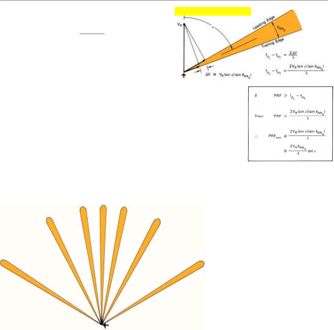
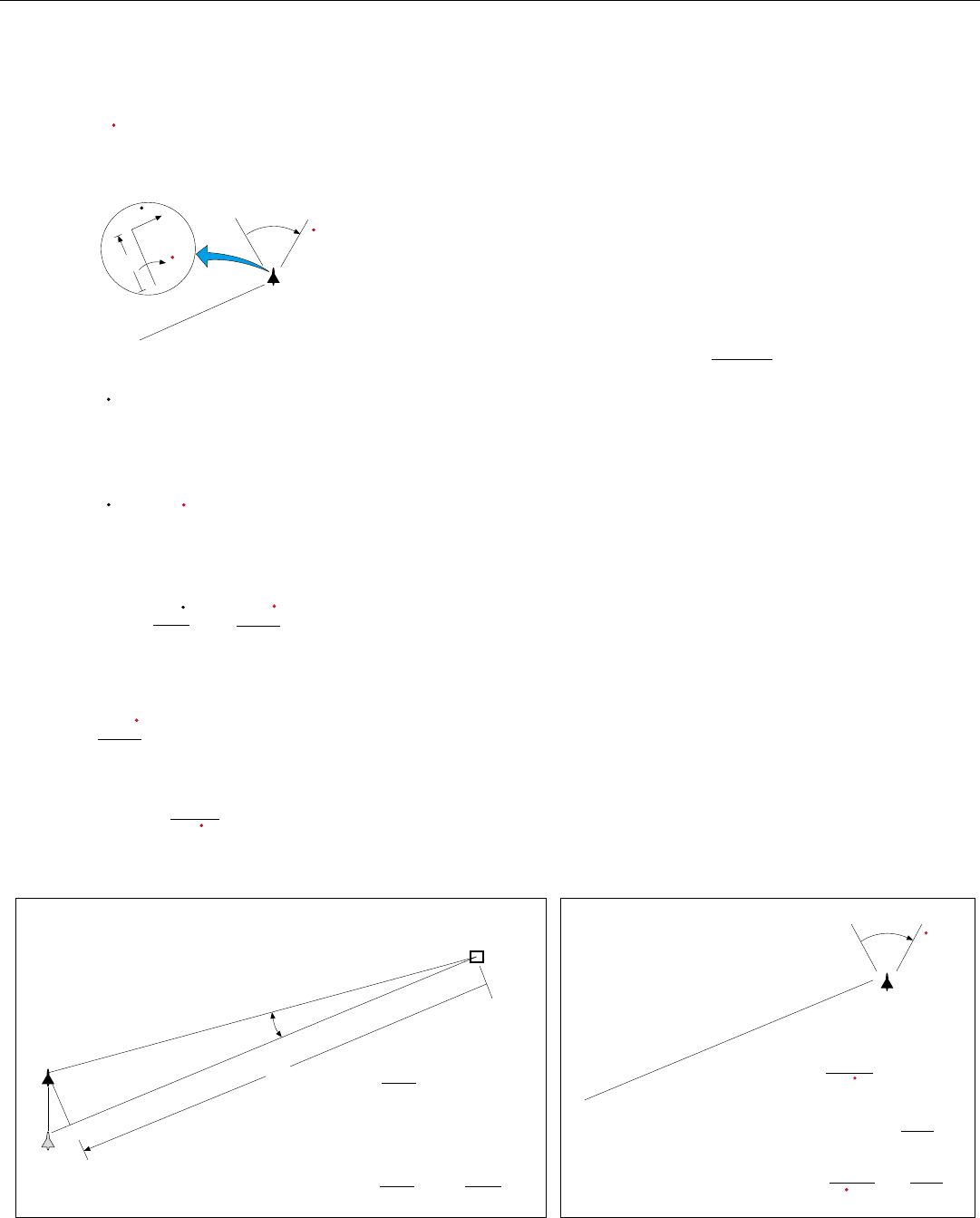
of the look angle, ε (Fig. 3). So the minimum acceptable
PRF is
PRF
min
≅
2 V
R
θ
NN
a
sin ε
λ
where
V
R
= velocity of the radar
θ
NN
a
= null-to-null azimuth beamwidth of
real antenna in radians
ε = azimuth look angle
λ = wavelength, units consistent with V
R
In typical airborne applications, V
R
is between 800 and
1500 feet per second.
1
Grating Lobes. Some people find the limitation on min-
imum PRF easier to visualize in terms of antenna theory. In
those terms, what determines the minimum PRF is the dis-
tance, d
e
, between successive array elements. Now, d
e
equals the radar's speed times the interpulse period, 1/f
r
. If
d
e
is greater than half a wavelength, as it generally will be
in most SARs, so-called grating lobes will be produced.
These are replicas of the mainlobe, occurring at increasingly
large intervals on either side of the mainlobe
2
(Fig. 4).
CHAPTER 32 SAR Design Considerations
427
3.
Geometric relationships
determining the spread
between doppler
frequencies of return
from leading and trail-
ing edges of the real
antenna’s mainlobe.
1. If we assume that
θ
NN
a
=
2λ/
l, where l is the length
of the real antenna, then
at an azimuth look angle
of 90˚, PRF
min
= 4V
R
/l.
4. Grating lobes are replications of an array’s mainlobe occurring
at increasingly large intervals on either side of the mainlobe.
Grating lobes are not unique to synthetic arrays. But
they are more of a problem in these arrays then in real
arrays. There are two reasons for this. First, because of the
restrictions on maximum PRF, the array elements generally
cannot be placed as close together in a synthetic array as in
a real array. Second, as we saw earlier, for a reflector at any
one angle off boresight, the difference in the phase shift of
the returns received by successive array elements is twice as
great in a synthetic array as in a real array.
2. They are called grating
lobes because they are the
kind of lobes produced
when monochromatic
light is passed through an
optical diffraction grating
(series of extremely nar-
row, closely spaced slits
in a flat plate).
Click for high-quality image
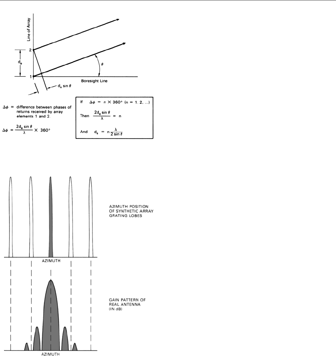
6. Minimum acceptable PRF places first grating lobe between
first and second sidelobes of real antenna.
PART VII High Resolution Ground Mapping & Imaging
428
How the lobes are produced can be explained as fol-
lows. If a reflector is gradually moved away from the bore-
sight line of the array, a phase difference develops between
the returns received by successive array elements (Fig. 5).
This difference is proportional to twice the spacing of the
elements times the sine of the azimuth angle (
θ
) of the
reflector relative to the boresight line. The familiar pattern
of nulls and sidelobes is thus observed.
However, if the spacing of the array elements is much
greater than half a wavelength, as the azimuth of the reflec-
tor is increased, a point is soon reached where the phase
shift is 180˚. Beyond this point, the amplitudes of succes-
sive lobes start increasing (sin [180 +
θ
] = – sin
θ
). The
increase continues until the element-to-element phase shift
reaches 360˚. At this point, the returns received by all of the
elements add up, once again, exactly as they did when the
reflector was in the center of the mainlobe. This “replica” of
the mainlobe is the first grating lobe.
If the azimuth of the reflector is increased further, the
process repeats and successive grating lobes appear.
In a real antenna, the gains of grating lobes fall off grad-
ually from that of the mainlobe with increasing azimuth
angles; but in a synthetic array, the fall off is much greater.
The reason for
this is that the synthetic array is formed from
returns received through the real antenna. The strength of the
returns received from any one direction, of course, is propor-
tional to this antenna’s two-way gain in that direction. In gen-
eral, that gain decreases rapidly as the azimuth angle increas-
es. If the azimuth angle of the first grating lobe can be made
sufficiently large, the amount of energy received through the
grating lobes can be reduced to negligible proportions.
Generally, the restriction imposed on the PRF by the
requirement that range not be ambiguous is reasonably
loose. So the PRF can usually be set high enough to place
the first grating lobe well outside the mainlobe of the real
antenna. If it can’t be, it is placed in a null between side-
lobes (Fig. 6). But it must not be placed closer to the main-
lobe than the second null.
3
To maintain the desired spacing between array elements,
as well as to keep the number of pulses that must be
processed in a given array length constant, a common prac-
tice is to adjust the PRF to the speed of the radar.
Minimizing Sidelobes
Performance of a synthetic array radar may be degraded
by both range sidelobes due to pulse compression and the
sidelobes of the synthetic array. The sidelobes affect the
radar maps in two different ways. First, the peaks of the
stronger sidelobes may cause a string of progressively weak-
5. Conditions under which grating lobes are produced. If spac-
ing between array elements (d
e
) times sine of angle
θ
off bore-
sight is a multiple of half a wavelength, returns received from
angle
θ
by successive elements will be in phase.
3. Since the angle
θ
N
between
this null and the boresight
line equals
θ
NN
, the PRF that
places the first grating lobe
here is the same as PRF
min
derived on page 427.
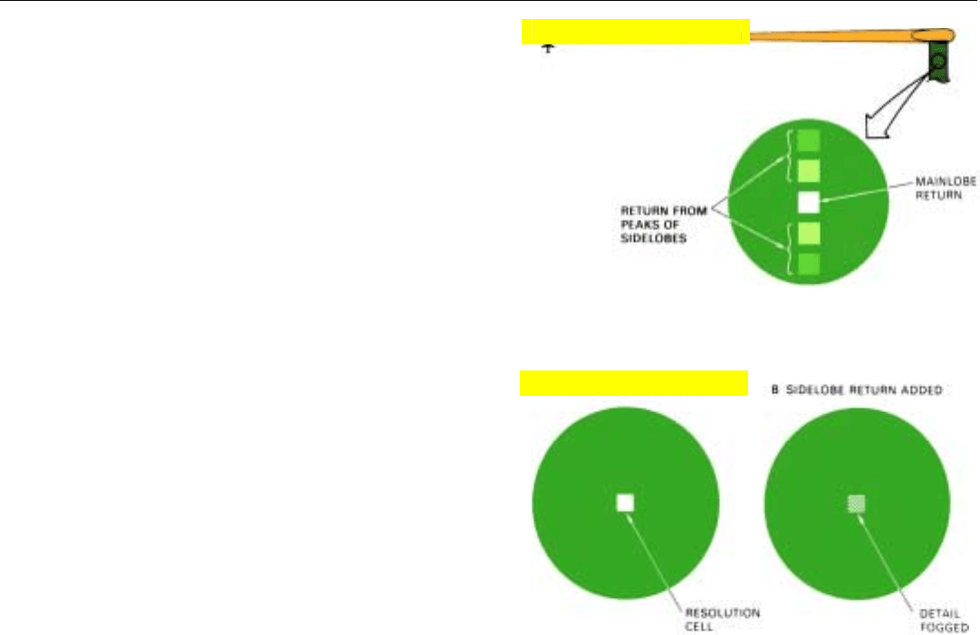
er false targets to appear on either side of a strong target
(Fig. 7).
Second, the combined power of all sidelobes—called
the integrated sidelobe return—together with receiver noise,
tends to fog or wash out the detail of the maps.
The effect of the integrated sidelobe return can be visu-
alized by imagining an area of ground the size of a resolu-
tion cell which produces no return—a smooth surfaced
pond, for example—in the middle of a region of uniform
backscattering—say a grassy field. The signal output when
the pond is being mapped is the sum of the simultaneously
received power of the range sidelobes and the azimuth side-
lobes (Fig. 8)—plus the receiver noise. To the extent that
this power is comparable to that received from the sur-
rounding terrain, the "hole" in the map corresponding to
the pond will be filled in. If nothing is done to reduce the
sidelobes, the integrated sidelobe return alone may contain
up to 10 percent as much power as the mainlobe return.
Consequently, the loss of contrast can be considerable.
Like the sidelobes of a real array, the sidelobes of a syn-
thetic array are produced by the elements at the ends of the
array. Consequently, just as the sidelobes of a real antenna
may be reduced through illumination tapering (see Chap.
8), the sidelobes of the synthetic array can be reduced by
weighting the returns received by the individual array ele-
ments (i.e., the returns from successive transmitted pulses)
so as to de-emphasize the returns received by the end ele-
ments relative to the returns received by the central ele-
ments. The cost of this reduction, of course, is a slight loss
of resolution. The weighting can be conveniently accom-
plished when the focusing corrections are applied to the
stored returns. The loss in resolution can be avoided by
increasing the array length (integration time), at the
expense of increased computational load.
Having reduced the range and azimuth sidelobes to
acceptable levels, the remaining loss in contrast due to
noise can be reduced by increasing the gain of the real
antenna or the average transmitted power.
Motion Compensation
In Chap. 31, it was assumed that the aircraft was flying
at constant speed in a perfectly straight line. But this is vir-
tually never the case. Since the whole SAR concept revolves
around the effect of very slight differences in the phases of
signals received over a comparatively long period of time,
typically 1 to 10 seconds, it is essential that any accelera-
tion of the aircraft during that period be compensated. The
acceleration may be measured either by accelerometers
mounted on the antenna or by a separate inertial navigation
CHAPTER 32 SAR Design Considerations
429
7. Close-up of a portion of a radar map showing effect of unsup-
pressed lower-order sidelobes when a strong point target is
mapped.
8. How integrated sidelobe return washes out detail. Cell in cen-
ter represents area from which no return is received.
Click for high-quality image
Click for high-quality image

PART VII High Resolution Ground Mapping & Imaging
430
system, the outputs of which are referenced to the phase
center of the antenna.
On the basis of the measured acceleration, phase correc-
tions are computed. These may be applied to the received
signals at virtually any point in the radar system, from local
oscillator to final integration. Where presumming is
employed, the corrections may, for example, be applied on
a sample-by-sample basis after the presumming.
Limit on Uncompensated Phase Errors
The common sources of phase errors and their effects on
the radar’s performance are listed in the table.
The significance of these errors cannot be overstressed.
It can be shown mathematically that an uncorrected low-
frequency phase error of only 114˚ from the center to the
ends of an array will result in a 10 percent spreading of the
synthetic beam. At X-band wavelengths, 114˚ amounts to
only about 3/8 of an inch. As you might expect from look-
ing at Fig. 9 of the last chapter, though, the predominant
effect of uncompensated phase errors usually is increased
sidelobe levels. As a rule, to keep these within acceptable
bounds, the total random (high-frequency) phase error
must be held to within 2 to 6˚. Yet at X-band, 6˚ of phase is
equivalent to an antenna motion of only 0.01 inch!
Summary
If not duly considered, certain aspects of SAR design
may seriously degrade the radar maps. Among the more
important are choice of PRF, sidelobe reduction, motion
compensation, and uncompensated phase errors.
Two primary factors influence the choice of PRF. The
maximum value is limited by the requirement that no range
ambiguities occur within the span of ranges from which
mainlobe return is received. The minimum value is limited
by the requirement that there be no doppler ambiguities
within the band of frequencies spanning the central spectral
line of the mainlobe return. In terms of antenna theory, this
same minimum PRF places the first grating lobe between
the first and second sidelobes of the real antenna.
A synthetic array’s stronger sidelobes may cause weak,
false targets to appear on either side of strong targets. And
the combined sidelobe return from all targets—integrated
sidelobe return—may wash out detail. The sidelobes may
be reduced through amplitude weighting.
Particularly important is motion compensation
—
measuring
the radar’s acceleration and introducing phase corrections
to compensate for deviations from a straight, constant-speed
course.
COMMON SOURCES
• Unmeasured velocity error
• Unmeasured acceleration along line
of sight during array time
• Non-linear motion of aircraft
• Equipment imperfection
• Processing approximations
• Atmospheric disturbances
EFFECTS
• Increased sidelobe levels
• Degraded resolution
• Reduced antenna peak gain
• Beam wander
PHASE ERRORS
431
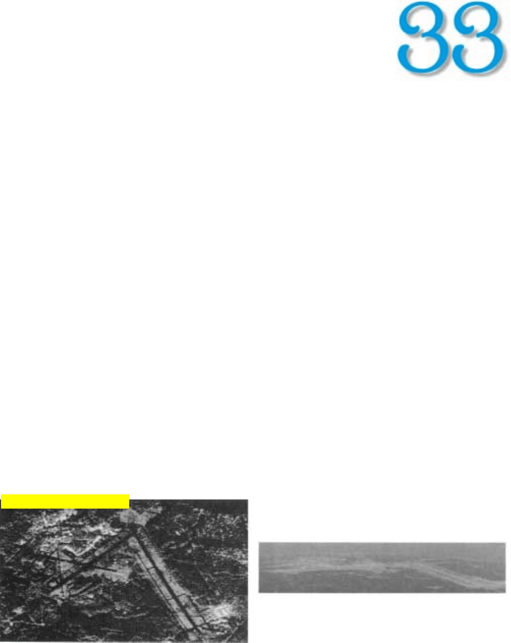
SAR Operating Modes
O
perationally, SAR has several striking advan-
tages. First, with a small physical antenna oper-
ating at wavelengths suitable for long-range
mapping, SAR can provide azimuth resolutions
as fine as a foot or so. Second, by increasing the length of
the array in proportion to the range of the area to be map-
ped, the resolution can be made independent of range.
Third, since the array is formed in the signal processor, the
basic SAR technique can conveniently be adapted to a wide
variety of operational requirements.
Added to these advantages are those of all radar map-
ping. Maps can be made equally well day or night, through
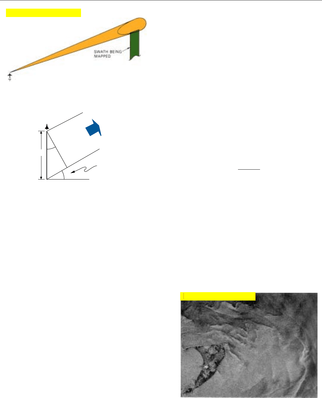
smoke, haze, fog, or clouds. The maps are plan views and
can be made even at shallow grazing angles (Fig. 1, below).
While simple strip-mapping described in Chap. 31 is
quite useful, it has been improved upon and adapted to
special requirements in a variety of modes. Some of the
more important of these are squinted array, multilook map-
ping, spotlighting, doppler beam sharpening, moving-target
display, and inverse SAR (ISAR) imaging. Each is briefly
described in the following paragraphs.
1. Comparison of real-time SAR map with an aerial photo of the same region. Map was made from range many times as great as that from
which photo was taken. Radar not only sees through haze, but provides a plan view.
Click for high-quality image
PART VII High Resolution Ground Mapping & Imaging
432
Squinted Array
In real-time SAR mapping, if the radar’s azimuth look
angle is 90º, the leading edge of the map may lag behind
the radar by as much as two full array lengths. This limita-
tion can readily be eliminated. By training the beam of the
real antenna forward and making an appropriate focusing
correction and coordinate rotation, the synthetic array can
be squinted ahead by any desired amount within a fairly
wide zone to the side of the aircraft (Fig. 2). It can similarly
be squinted behind. The radar can thus be made to map
not only territory which it has long since passed, but terri-
tory which lies far ahead.
A price, of course, must be paid for this versatility. For,
as viewed from the patch being mapped, the effective
length, L
eff
, of the synthesized array is foreshortened in pro-
portion to the cosine of the squint angle, A (Fig. 3). The
azimuth (cross-range) resolution distance, d
a
, is corre-
spondingly reduced.
d
a
=
λR
2L cos A
But this reduction is generally a small price to pay for the
increased utility of the maps obtained.
Multilook Mapping
Sometimes the beam of the real antenna may be wide
enough to enable the same area to be mapped several times
without changing the antenna’s look angle. This is called
multilook mapping. When the maps are superimposed (i.e.,
when successive returns from each resolution cell are aver-
aged), the effects of scintillation are reduced.
Most of the maps used as illustrations in these chapters
were made with more than one look (Fig. 4).
A
A
Squint Angle
L
eff
L
eff
= L cos A
L
To ground patch
being mapped
Synthesized
Array
Antenna
Broadside direction
2. If beam of real antenna is squinted forward and appropriate
focusing correction and coordinate rotation are made, region
ahead can be mapped.
3. Foreshortening of synthesized arrary that occurs when radar
beam is squinted forward (or backward) by an angle A for
SAR mapping.
4. All of SEASAT’s maps were made with four looks. In this one,
surface waves around Nantucket Island reflect the contours of
the ocean floor. (Courtesy Jet Propulsion Laboratory)
Click for high-quality image
Click for high-quality image
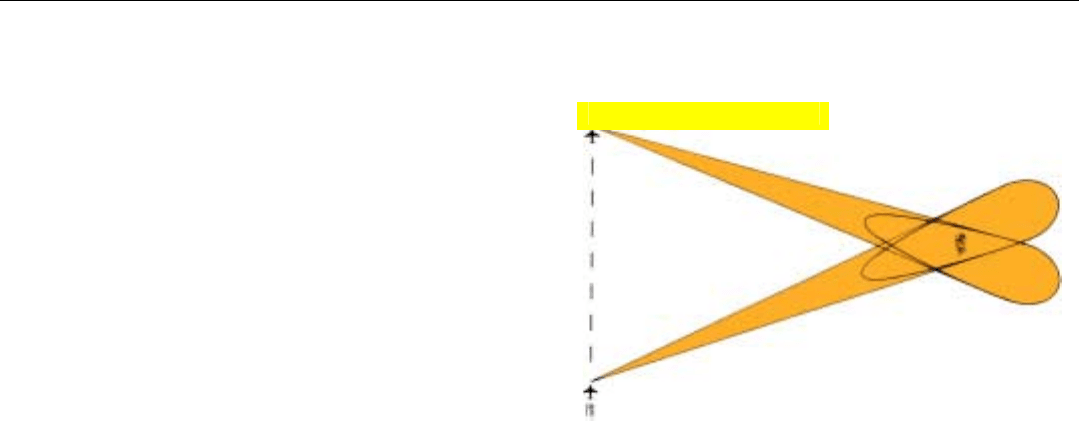
Spotlight Mode
By gradually changing the look angle of the real antenna
as the radar advances and making appropriate phase correc-
tions, the radar can repeatedly map a given region of inter-
est. This mode, called spotlight, not only enables the opera-
tor to maintain surveillance over an area for an appreciable
period of time but can produce maps of superior quality.
Quality may be improved in three basic ways. First, since
the beam is continuously trained on the area being
mapped, the length of the synthetic array is not limited by
the beamwidth of the real antenna.
Second, the size of the real antenna can be increased
without reducing the array length. By using a larger anten-
na, the mainlobe gain can be increased and the signal-to-
noise ratio correspondingly improved (Fig. 5).
The third way in which spotlighting improves the quality
of a map is by filling in gaps in the backscatter from points
on the ground. In Chap. 30, you may recall, it was pointed
out that when a radar illuminates an object on the ground
—such as a parked airplane—from a given angle, mappable
returns may be received from only a few main scattering
centers. The reason (explained on page 394) is that in terms
of fractions of wavelengths, hence radio frequency phase,
the distances from the radar to the various scatterers com-
prising the airplane may differ in such a way that much of
the scatter does not combine constructively in the radar’s
direction. The net result is that the airplane’s shape is not
necessarily as easily recognized as one would expect from
the ratio of the aircraft’s principal dimensions to the size of
th radar’s resolution cells.
In the case of distributed targets, such as fields, grass-
lands, paved areas, etc., this same effect makes the
backscatter spotty. The result in this case is a general graini-
ness of the images.
Since the wavelength is usually comparatively short, the
relative distances to the individual scatters (in fractions of
wavelengths) can change markedly when the same area is
viewed from slightly different angles. Consequently, the
graininess may be considerably reduced by repeatedly
mapping the same region from points progressively farther
along on the flight path and averaging successive returns
from each resolution cell.
The quality of the maps may be further enhanced by
periodically switching from one to another of several differ-
ent radio frequencies. These should be separated by at least
the bandwidth of the transmitted pulses, and the switching
should be done at points that are one or more array lengths
apart. By similarly changing the polarization of the antenna,
the quality may be improved even further.
CHAPTER 33 SAR Operating Modes
433
5. In spotlight mode, the beam of the real antenna is held on a
given region of interest so that it can be mapped repeatedly
from different angles and the array length can be increased,
without decreasing the size, hence the gain, of the real
antenna.
Click for high-quality image
PART VII High Resolution Ground Mapping & Imaging
434
Doppler Beam Sharpening (DBS)
This mode differs from other SAR modes in that the
length of the array is not increased in proportion to the
range of the area to be mapped but is the same for all
ranges. The maps, therefore, are the same as those pro-
duced by a real array having an extremely narrow beam—
hence the name doppler beam sharpening.
Typically, the antenna continuously scans the region of
interest on one side of the flight path or the other, or both.
Because the integration time is limited to the length of time
a ground patch is in the antenna beam—or, if you prefer,
the length of the array that can be synthesized is so limit-
ed—the resolution is coarser than can be achieved with a
nonscanning antenna. Moreover, since the integration time
is the same for the returns from all ranges, the azimuth res-
olution distance increases with range, rather than being
independent of it.
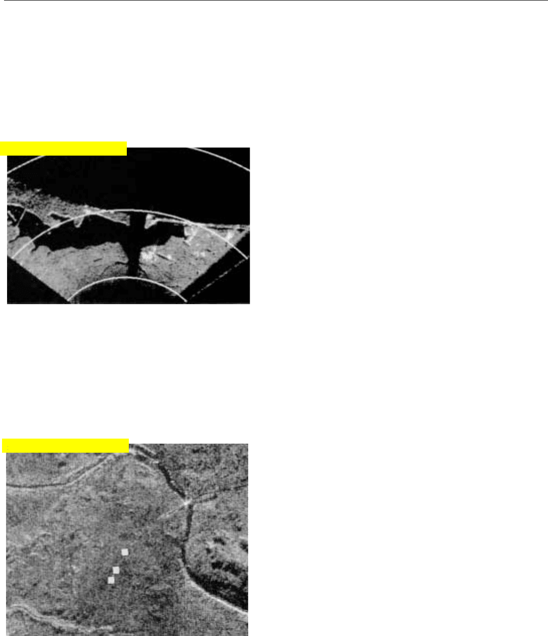
Nevertheless, except for the region directly ahead
(Fig. 6), where there is little or no spread in the doppler fre-
quencies within the mainlobe, the resolution is much finer
than could be achieved by the real antenna. Also, in con-
trast to the higher resolution modes, DBS can provide a
continuously updated map of a large expanse of ground.
Implementation is similar to that of the other SAR modes.
In one advanced design, the gap in the region ahead is filled
in by scanning it in a phase-comparison-monopulse detec-
tion mode providing substantially finer resolution than con-
ventional real-beam mapping (see APN-241, Part X).
Moving Target Display
Frequently, it is desired to show ground-moving targets on
the SAR map. Most of these are essentially point-source
reflectors: cars, trucks, etc. Because of their motion while the
radar is collecting the returns from which to synthesize the
array, they tend to wash out in the map. To detect them, a
ground-moving-target-indication (GMTI) mode is generally
interleaved with SAR mapping. Markers indicating the tar-
gets’ positions (Fig. 7)—and in some cases their range rates
as well—are then superimposed on the SAR map. In one
intriguing design, GMTI and SAR mapping are performed
simultaneously with the same antenna (see APG-76, Part X).
Bigger, larger-RCS targets, such as trains, are clearly visi-
ble on most SAR maps. If a train is moving and has a com-
ponent of velocity toward or away from the radar, however,
the resulting doppler shift will normally be interpreted by
the radar as indicative of a displacement in the cross-range
direction. As a result, the train will be displayed as though
it is traveling off its tracks. In more advanced SAR systems,
the error is sensed and the train is put back on its tracks.
6. With doppler beam sharpening, the antenna scans a wide
region—in this case on both sides of the flight path. Except
for the region directly ahead, resolution is comparable to
that achieved by a real antenna having an exceptionally
narrow beam.
7. Markers indicate locations of moving targets.
Click for high-quality image
Click for high-quality image
Inverse SAR (ISAR) Imaging
The classic SAR is ill-suited for imaging targets such as
ships and aircraft which have rotational motion. For unless
the differential doppler shifts which such motions produce
are accurately predicted and compensated, they tend to
defocus the array and blur the image.
With slightly different algorithms, however, these shifts,
rather than those due to the radar’s forward motion can be
used to provide the angular resolution needed for imaging
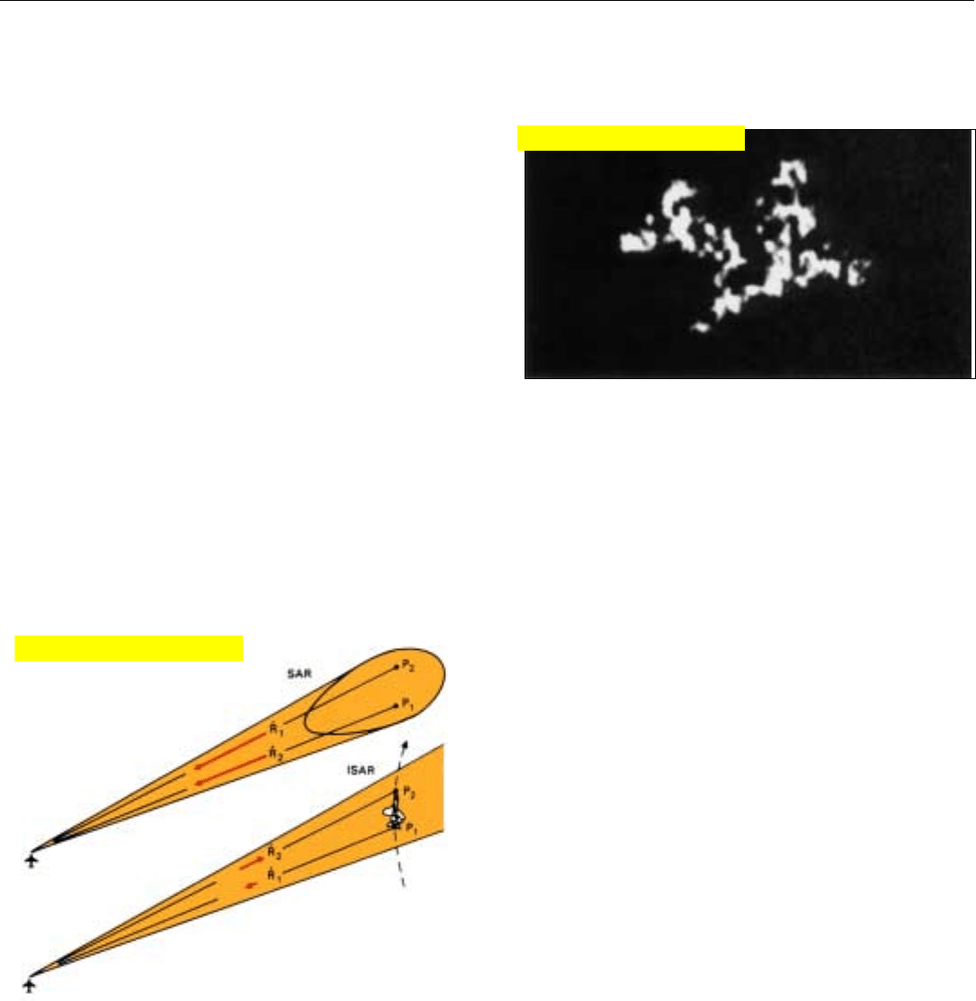
a target (Fig 8). The technique then is called inverse SAR,
or ISAR.
ISAR is most easily explained by starting with the SAR
spotlight mode. As we have seen, in it the radar spotlights
the ground patch that is to be mapped and records the
returns received over a period of time. Returns simultane-
ously received from points at different azimuth angles are
then separated on the basis of differences in their doppler
(phase) histories due to the corresponding differences in
the points’ range rates.
With ISAR, the principle is the same. But the differences
in range rate are those due to rotation of the spotlighted
target about its yaw, pitch, and roll axes, as seen by the
radar. This difference is illustrated in Fig. 9.
CHAPTER 33 SAR Operating Modes
435
Since the target shown in Fig. 9 is turning away from the
radar (rotating clockwise) the range rate of point P
1
on the
tail is slightly lower than the range rate of point P
2
on the
nose. Consequently, the doppler frequency of the returns
from P
2
and all points on the target between it and P
1
differ
in proportion to their distances from P
1
.
9. With conventional SAR, the differences in doppler frequency
which enable fine angular resolution to be obtained are due
to the forward motion of the radar-bearing aircraft. With
ISAR, the differences are due to the angular rotation of the tar-
get as seen by the radar
8. An ISAR image of a fighter aircraft.
Click for high-quality image
Click for high-quality image
PART VII High Resolution Ground Mapping & Imaging
436
To make an image of the target, phase corrections must
first be made to compensate for the displacement of the tar-
get relative to the radar while it collects the returns from
which the image will be produced. This is called motion
compensation. The returns from each resolvable range
increment are then applied to a separate bank of doppler
filters, and an image is produced from their outputs just as
in conventional SAR mapping.
As shown in the panel (left), the image’s cross-range reso-
lution, d
n
, is proportional to the ratio of the doppler filters’
3-dB bandwidth, BW
3dB
, to the target’s rate of rotation,
θ
⋅
.
d
n
=
BW
3db
λ
2
θ
⋅
The cross-range dimension, though, is not necessarily
horizontal, as with conventional SAR, but perpendicular to
the axis about which the target happens to be rotating. No
image is formed, of course, if that axis is colinear with the
radar’s line of sight, or if the target has no rotational motion
as viewed from the radar.
Besdies imaging targets having rotational motion, ISAR
has another important advantage over conventional SAR.
This advantage is illustrated in Fig. 10 (below).
With SAR, the cross-range resolution distance, d
a
, is
inversely proportional to the angle,
θ
, through which the
radar flies during the doppler filters’ integration time, t
int
.
With ISAR, the cross-range resolution distance d
n
is
inversely proportional to the angle,
θ
, through which the
target rotates during t
int
. The radar need not fly through any
angle to obtain an image of a target. In fact, the ISAR image
of a fighter aircraft shown in Fig. 8 on the preceeding page
was made by a stationary radar on the ground.
Assuming that
θ = Target’s rate of rotation.
d
n
= Desired cross-range
resolution
As is clear from the diagram,
∆R = incremental increase in
range rate of points on the
target separated by the
distance, d
n
, normal to the
line of sight from the radar
∆R= d
n
The resulting difference in the doppler
frequencies of the radar returns from
successive points on the target is
∆f
d
= =
The minimum difference in doppler frequency
the radar can resolve equals the 3-dB
bandwidth of its doppler filters. Accordingly,
= BW
3dB
making the cross-range resolution distance,
d
n
=
CROSS-RANGE RESOLUTION
OF ISAR IMAGES
2 ∆R
λ
θ
θ
Line of sight
from radar
Target
θ
d
n
∆R
θ
θ
2 d
n
λ
θ
BW
3dB
λ
2
θ
2 d
n
λ
θ
θ
L
eff
≈ θ R
θ
Ground patch
mapped
L
eff
θ
R
d
a
= R
λ
2 L
eff
∴ d
a
≈ R ≈
λ
2
θ R
λ
2 θ
SAR
ISAR
Line of sight from radar
θ is the angle the target has
rotated through in the integra-
tion time, t
int
,
of the radar's
doppler filters.
Target
“Imaged”
d
n
= λ
2
BW
3dB
t
int
BW
3dB
≈
1
∴ d
n
≈ ≈
2 θ t
int
λ
2 θ
λ
θ
θ
θ
θθ
θ
θ is the angle the radar has flown
through in the integration time, t
int
,
of the radar’s doppler filters.
θ
θ
10. With conventional SAR, the cross-range resolution distance, d
a
, is inversely proportional to the angle,
θ
, the radar flies through during the
doppler filters’ integration time, t
int
. With ISAR, the cross-range resolution distance, d
n
, is proportional to the angle,
θ
, the target rotates
through in t
int
.
