George W. Stimson introduction to Airborne Radar (Se)
Подождите немного. Документ загружается.


PART VIII Radar in Electronic Warfare
448
Gate Stealing Deception
If, despite noise jamming, bin masking, and false targets,
a threat radar manages to lock onto a screened target, a gate
stealer may keep the radar from usefully tracking the target.
In essence, the stealer disrupts tracking by transmitting
false target returns contrived to capture the gate which the
radar places around the aircraft
’s
skin return for clutter
reduction and tracking.
Having captured the gate, the stealer may do one of the
following:
• “Walk” it off the skin return, causing the radar to pro-
vide false range and range-rate data
• Break lock, by pulling the gate off the skin return, and
dropping or transferring it to chaff return or clutter
• Facilitate angle deception countermeasures by increas-
ing the jamming-to-signal ratio
By repeatedly breaking lock every time the victim radar
relocks on the skin return, the stealer can drastically reduce
the radar’s tracking accuracy.
Gate stealers are of two basic types: range-gate stealers
(RGS) and velocity-gate stealers (VGS).
6
Range Gate Stealers. These are typically used against
radars operating at low or medium PRFs.
Against noncoherent radars (low PRF only), the stealer
may be mechanized with a transponder. It detects the lead-
ing edge of each radar pulse and, after a delay, transmits an
RF pulse
7
back to the radar.
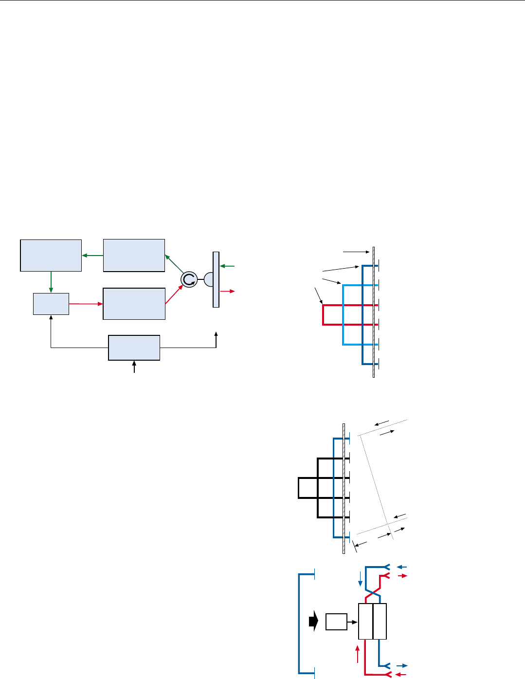
Initially the delay is made short enough that successive
pulses cover the skin return. Being very much stronger than
it, they capture the range gate. The time delay is then grad-
ually increased, pulling the gate out in range and off the
skin return (Fig. 17).
17. Against a noncoherent radar, the range-gate stealer may be mechanized with a transponder. Upon receipt of each radar pulse, the
transponder transmits a delayed RF pulse to the radar.
6. Another type of gate stealer is
the so-called chirp-gate stealer.
It shifts the chirp frequency
used for pulse compression
up or down, thereby moving
the range gate out or in, in
range.
7. Or possibly gated spot noise.
Time
Received Radar Pulse
Delay
Time
Received Radar Pulse
Delay
Time
Initially. Delay is set so that
successive transponder pulses
cover the skin return and thus
capture the radar’s range gate.
Delay
Transponder’s
Pulse
Then: The delay is gradually
increased, so the transponder
pulse will pull the radar’s range
gate out in range.
Finally: The delay has been
increased enough for the range
gate to be pulled completely off
the skin return.
ived Radar Pulse
If the radar’s PRF is known or has been measured by the
stealer’s logic, by initially making the delay equal to the
interpulse period and then gradually reducing it, the gate
can instead be pulled in in range.
Against coherent radars—for which the doppler frequen-
cy of the skin return must be matched—the range-gate
stealer is implemented with a repeater.
Older designs, using circulating-delay-line memories,
• Sample the leading edge of each received pulse
• Delay the sample for the desired length of time
• Amplify and beam the sample back to the radar
Since only the leading edge of the pulse is stored, any pulse
compression coding is not repeated.
Newer designs repeat the coding with a DRFM
8
(Fig. 18).
CHAPTER 34 Electronic Countermeasure (ECM) Techniques
449
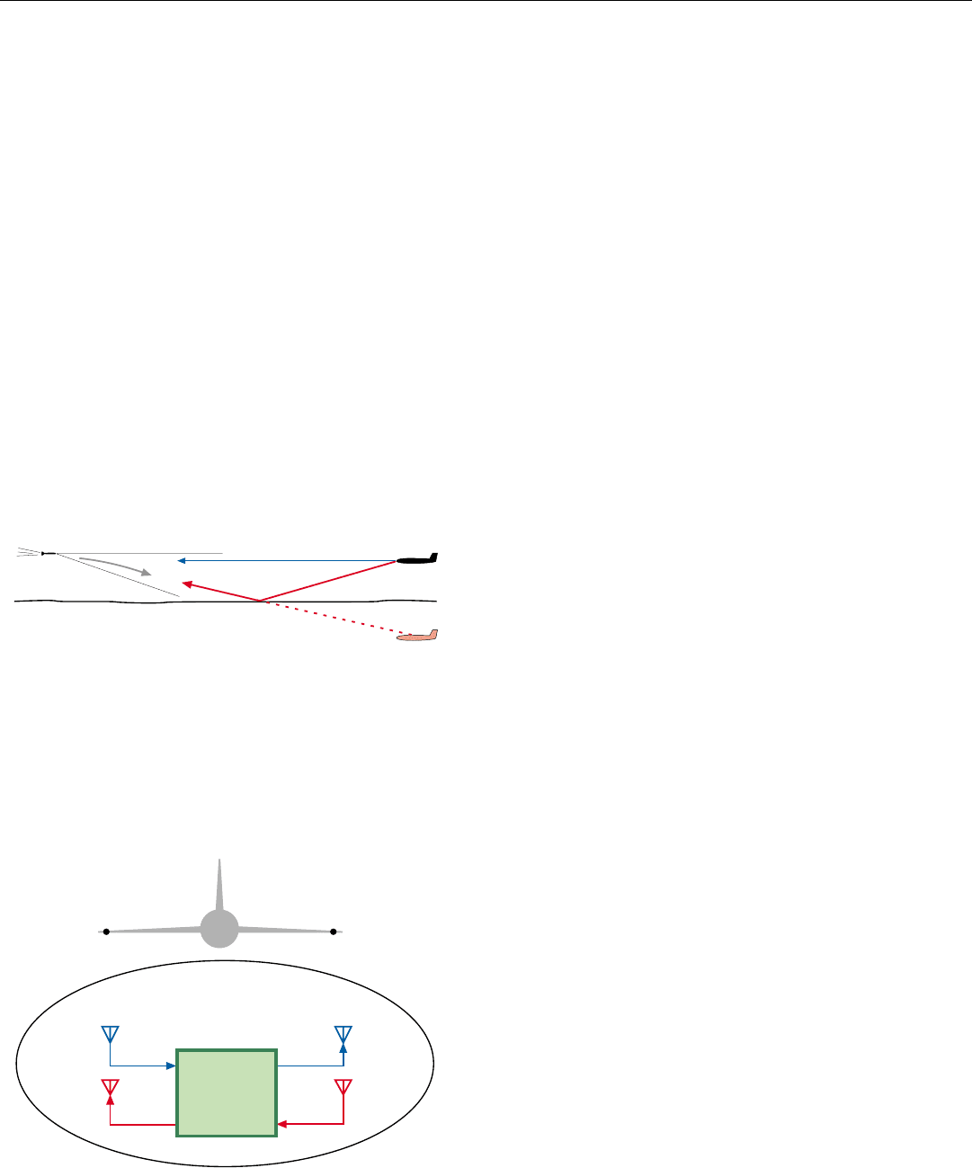
18. A more capable range-gate stealer for use against a coherent
radar. DRFM stores each received pulse enabling stealer to
match doppler frequency and pulse-compression coding of
skin return. Antenna is trained on radar by ECM receiver.
RETRODIRECTIVE REPEATER
cables the same length. Thus, the progressive phase
lag in the radiation received by successive elements
from a direction not normal to the array is reversed in
Operation of the Retrodirective Repeater is best ex-
plained by first considering a simple passive retrodirective
antenna. It consists of a linear array of radiating elements,
interconnected in pairs by coaxial cables.
Face Plate
Equal
Length
Cables
1
2
3
4
5
6
Radiation received by each
element is reradiated by the
other element of the pair. In
the array shown here, for in-
stance, radiation received by
element #1 is reradiated by
element #6, and radiation
received by element #6 is re-
radiated by element #1.
The delay incurred in pas-
sing through the cables is
equalized by making all of the
the reradiated signal. To
illustrate, the radiation
emitted
from element #6
leads the radiation emit-
ted from element #1 by
the same length of time
(∆t)—hence phase—that
the radiation
received
by
element #6 lags the radi-
ation received by #1. Ac-
cordingly, the composite
radiation from all elements
propagates in a direction
exactly opposite that of the
received radiation.
By replacing each pair
of radiators and its
interconnecting cable
in the above-described
antenna with a pair of
repeaters, a retrodirective
repeater may be
implemented.
2
3
4
5
1
6
Line of equal phase
∆t
1
6
T
W
T
T
W
T
1
6
Mod.
8. Or a pulse-compression
code memory.
Amplifies
Delayed Pulses
Trained on
Victim Radar
Variable
Delay
Holds Pulses
In DRFM
Receives
Radar’s Pulses
Control
From ECM Receiver
Velocity-Gate Stealers. These are typically used against
high-PRF and CW radars and missile guidance seekers.
Consisting of a straight-through repeater, such as was illus-
trated in Fig. 12, the velocity-gate stealer performs essen-
tially the same function in the frequency domain as a range-
gate stealer does in the time domain.
Initially the received radar signal is amplified and trans-
mitted back without modification. Thus synchronized with
the skin return in doppler frequency, the much stronger
repeater signal captures the gate the radar uses to isolate
and track the skin return in doppler frequency (velocity).
The radio frequency of the repeated signal is then gradually
shifted up, or down, pulling the gate off the skin return.
In some mechanizations, the retransmitted pulses are
automatically beamed toward the victim radar by a retrodi-
rective antenna (see panel, right). It, unfortunately, requires
much more space than a simple antenna, such as a spiral,
and so has limited applicability.
PART VIII Radar in Electronic Warfare
450
Coordinated Range/Velocity Gate Stealing. While
described here singly, range and velocity gate stealing may
be performed in concert. By employing a repeater having
a DRFM, the combined techniques may be made much
more difficult to counter than either technique alone.
Angle Deception
The object of this countermeasure is to introduce angle-
tracking errors in an enemy’s fire-control radar or radar-
guided missiles, causing his weapons to miss.
Errors were introduced in early angle-tracking systems
that employed lobing simply by sending back suitably
timed false returns.
Several techniques have been devised for introducing
errors in the more advanced, monopulse tracking systems.
All of these, however, require fine-grain information on the
victim radar’s parameters, which may not be available.
More robust techniques capable of defeating both
monopulse and lobing are terrain bounce, crosseye, cross
polarization, and double cross.
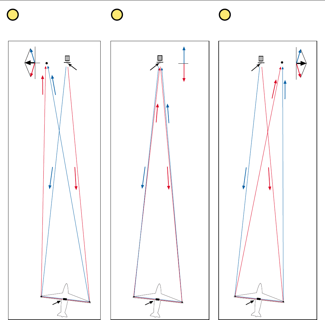
Terrain Bounce Jamming (TBJ). Intended for low-alti-
tude short-range engagements, terrain bounce is an effec-
tive defense against an approaching radar guided missile. A
repeater in the threatened aircraft is equipped with a direc-
tional antenna whose beam is deflected downward to
bounce false returns off the terrain in front of the missile
(Fig. 19).
Overpowering the directly received skin returns,
9
the
bounced signal causes the missile to head for a virtual tar-
get image beneath the surface and miss the aircraft.
Crosseye. For this deception, the aircraft to be protected
is equipped with a repeater having exceptionally high gain
and receiving and transmitting antennas installed as close
as practical to each wing tip (Fig. 20). The repeater is
mechanized in such a way that
• Signals received from the threat radar by the receiving
antenna on the left wing tip are shifted in phase,
amplified, and returned to the radar by the transmit-
ting antenna on the right wing tip
• Signals simultaneously received from the radar by the
receiving antenna on the right wing tip are similarly
shifted in phase, amplified, and returned to the radar
by the transmitting antenna on the left wing tip
• Phase shifts incurred in passing through the repeater
are such that the signal retransmitted from one wing
tip is very nearly 180° out of phase with the signal
retransmitted from the other wing tip.
19.
Terrain bounce. Downward deflected antenna in target bounces
false echoes off terrain in front of missile, causing it to steer for
a virtual image.
20. Crosseye is implemented with a repeater having transmit and
receive antennas on both wing tips. Signals received at right
wing tip are retransmitted from the left wing tip and vice
versa. To ensure extreme stability of gain and phase, both sig-
nals time share the same TWT amplifier chain.
9. Plus directly received sidelobe
radiation from the repeater.
Virtual
Image
Missile
Skin return
False echoes
Target
+90°
-90°
Transmit
Receive
Transmit
Receive
AntennasAntennas
Extremely
High-Gain
Repeater
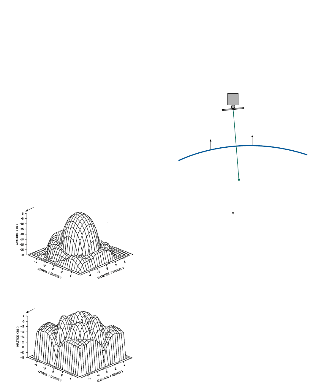
As illustrated in Fig. 21, in going from the radar anten-
na’s phase center, through the repeater, and back to the
phase center, the two signals traverse exactly the same
round-trip distance. Because of the nearly 180° phase dif-
ference imparted by the repeater, they essentially cancel.
10
But at points to the right and left of the phase center, the
round-trip distances traversed are increasingly different. As
a result, the phase difference imparted between the signals
by the repeater is correspondingly reduced, and they com-
bine to produce an appreciable sum. The magnitude of the
CHAPTER 34 Electronic Countermeasure (ECM) Techniques
451
21. How the reradiated crosseye signals combine upon returning to the victim radar.
To left of the phase center, path A is
longer; path B is shorter. So signals are
partially in phase and produce a sum.
At antenna’s phase center, distances
traveled via paths A and B are equal. So,
signals are out of phase. Sum ≈ 0
To right of the phase center, path B is
longer; path A is shorter. So signals are partly
in phase, but sum is reversed.
12
3
B
A
Sum
Victim Radar
Phase
Center
A
A B
B
Sum ≈ 0
A
B
Victim Radar
Phase
Center
A
A B
B
Crosseye
Repeater
Victim Radar
Phase
Center
Crosseye
Repeater
AB
A B
B
A
Sum
Crosseye
Repeater
10. The reason for making the
signals nearly but not exactly
180º out of phase is to ensure
that there will be some output
from the “sum” channel of a
monopulse radar’s antenna.
Otherwise, crosseye would
not be able to drive the anten-
na off the target.
PART VIII Radar in Electronic Warfare
452
sum increases with the distance of the points from the
phase center. What’s more, the sum on the right is 180° out
of phase with the sum on the left.
Consequently, when the crosseye signals merge with the
skin return, they warp the return’s phase front so that it is
not quite normal to the line of sight to the Crosseye-bearing
aircraft. Consequently, in aligning the face of the antenna
with the warped phase front, the radar’s angle tracking sys-
tem trains the antenna in a direction offset to one side.
22. When crosseye’s signals combine with the skin return, they
warp its phase front, causing the victim radar to train its
antenna off to one side of the crosseye-bearing aircraft.
23. Effect of a strong cross-polarization—such as crosspol’s—on
the receive pattern of a planar array antenna in its radome.
Mainlobe is replaced by four lobes, on the diagonal axes,
whose peak gain is reduced by more than 25 dB. Such dis-
tortion results in large and erratic tracking errors.
Victim Radar
Radar trains its antenna
in direction normal to
phase front.
Line of sight to
Crosseye-bearing
aircraft
Phase front of
combined skin return
and Crosseye signals.
Up to a limit that depends primarily on the separation of
the crosseye antennas, the stronger the crosseye signals are
relative to the skin return, the greater the warp; hence, the
greater this offset will be. By slowly varying the amplitude
or phase of the crosseye signals, it is possible to walk the
radar antenna off the target.
Cross Polarization. “Crosspol,” or polarization-exchange
cross modulation (PECM) as this countermeasure is also
called, takes advantage of a distortion in the polarization of
a radar’s received signals due to several possible causes: the
curvature of the radome; the diffraction occurring at the
edges of the antenna; and, in parabolic reflector antennas,
the curvature of the reflector.
Because of this distortion, when an antenna is illuminat-
ed with a very strong signal whose polarization is rotated
90° relative to that of the antenna, the antenna’s receive pat-
tern becomes distorted (Fig. 23). As a result, large and
erratic tracking errors build up.
NORMAL RESPONSE
CROSSPOL RESPONSE
0 dB = 36.4 dBi
0 dB = 11.0 dBi
Towing has the advantage that the decoy is reusable, but
restricts the aircraft’s maneuverability. The restriction is
minimized by designing the decoy to have very little drag,
and possibly by incorporating control surfaces in the decoy
to control its position relative to the towing aircraft.
Expendable decoys (Fig. 26) are more versatile. They
can, for example, pull ahead of the deploying aircraft, fall
behind it, or gradually assume a radically different course.
This capability is gained at the expense of providing self-
contained propulsion and navigation systems and of the
decoys not being recoverable.
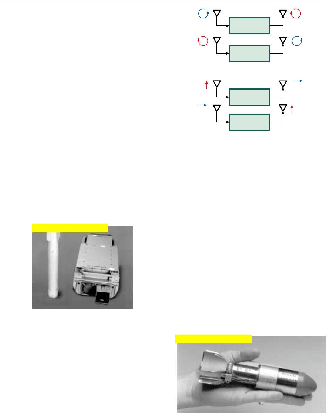
Crosspol is implemented with a repeater employing a
high-gain TWT-amplifier chain and oppositely polarized
receiving and transmitting antennas.
If the victim radar is linearly polarized, in order for the
repeater’s operation to be independent of the direction of
the polarization, circularly polarized antennas may be
used—right-hand for reception; left-hand for transmission;
or vice versa (Fig. 24a).
If the victim radar is circularly polarized, the repeater
may employ two channels of roughly equal gain and
orthogonal linearly polarized antennas (Fig. 24b). So that
the deception can be unobtrusively introduced, the
repeaters’ gain is adjustable.
Double Cross. As the name implies, double cross is a
combination of crosseye and crosspol. Though more com-
plex, it can be more difficult to counter.
Radar Decoys
Radar decoys may be deployed to confuse an enemy and
draw his radar, or the seeker of an approaching radar guid-
ed missile, away from the deploying aircraft. Decoys are of
two basic types: towed and expendable.
A towed decoy is attached to a thin cable, which can grad-
ually be reeled out as much as 300 feet behind the aircraft
(Fig. 25).
CHAPTER 34 Electronic Countermeasure (ECM) Techniques
453
24. Possible implementations of crosspol. To make implementa-
tion independent of direction of victim radar’s polarization,
two channels are used.
25. A towed decoy and the launcher/launch controller used in
the F-16. Decoy is packaged in a sealed canister which also
contains the payout reel (Courtesy of Raytheon Company)
TWT Chain
Hor.
Vert.
Hor.
TWT Chain
Right
Circular
Polarization
TWT Chain
Left
Circular
Polarization
(a) Against a linearly polarized radar, Crosspol would use
circularly polarized antennas of opposite hand.
(b) Against a circularly polarized radar, Crosspol would use
linearly polarized antennas of opposite sense.
TWT Chain
Right
Circular
Polarization
Left
Circular
Polarization
Vert.
26. An active expendable decoy used by the U.S. Navy and RAF.
(Courtesy of Raytheon Company)
Click for high-quality image
Click for high-quality image

PART VIII Radar in Electronic Warfare
454
Decoys of both types may be designed to produce the
desired radar returns either passively or actively. Since a
decoy is necessarily quite small, for passive operation its
radar cross-section must generally be augmented. This may
be accomplished with a corner reflector or a Luneberg lens
(Fig. 26), both of which are comparatively simple and inex-
pensive.
Active decoys generally carry a repeater and need a con-
trol system and power supply. Also, for small decoys, isolat-
ing transmit and receive antennas is a challenging prob-
lem—all of which makes the decoys more expensive.
Regardless of the mechanization, to achieve its purpose a
decoy must:
• Have an RCS greater than twice that of the aircraft
• Initially, match the deploying aircraft’s speed
• For tracking-gate pull-off, initially appear in conjunc-
tion with the deploying aircraft as a single target
• Not exceed reasonably expected accelerations
Provided these conditions are met, an appropriately con-
trolled decoy deployed in synchronism with a critically
timed evasive maneuver may save an aircraft from almost
certain destruction by a radar guided missile.
Future Trends
As radar capabilities grow, they will, as always, be
matched by more severe and increasingly sophisticated
ECM.
The RF coverage and responsiveness of noise jammers
will increase. Their effectiveness in standoff and escort mis-
sions will undoubtedly grow.
Deception ECM will similarly advance. False targets will
become increasingly deceptive, electronically flying realistic
profiles and exhibiting the electronic signatures of friendly,
neutral, or hostile aircraft. The present gate-stealing, ter-
rain-bounce, crosseye, and crosspol techniques will be
refined. New angle deception techniques, not presently
envisioned, may also evolve.
ECM systems will become more intelligent, more respon-
sive. They will adjust agilely to changes in the encounter
scenario, to changing radar characteristics, even to new
waveforms and ECM thwarting radar responses.
Summary
Chaff, the simplest of all ECM, can screen an entire raid
from radars operating over a wide range of frequencies. But
moving-target indication rejects chaff return.
Noise jamming screens targets by swamping out all but
26. In simplest form, a Luneberg lens reflector consists of a dielec-
tric sphere. Its index of refraction increases from 1 at the sur-
face to a maximum at the center, bending the rays of an
incoming plane wave so that they converge at a point on the
opposite surface. There, a metal coating reflects the wave
back in the direction from which it came.
Metal
Coating

ACRONYMS OF ECM
• RBM — Range-Bin Masking, or “Cover Pulse”
• VBM — Velocity-Bin Masking, or “Doppler Noise”
• RGS — Range-Gate Stealer
• VGS — Velocity Gate Stealer
• VGPO — Velocity-Gate Pull-Off
• VGWO — Velocity-Gate Walk-Off
• DRFM — Digital Radio Frequency Memory
• TBJ — Terrain Bounce Jamming
• PECM — Polarization-Exchange Cross-
Modulation (Crosspol)
Bin Masking Techniques
False Targets
Gate Stealing
Angle Deception
the strongest target returns. For maximum efficiency it
must be concentrated at the radar’s frequency (spot jam-
ming) and in those range or doppler bins where the returns
to be masked may appear (bin masking).
Against multiple radars operating on different frequen-
cies, the jamming may be spread over the entire operating
band (barrage jamming), swept through that band (swept
spot jamming), or concentrated at each radar’s frequency
(multiple spot jamming).
Jamming prevents a threat radar from measuring target
range and range rate and assessing raid size. By coopera-
tively blinking their jamming, closely grouped aircraft may
confound the enemy’s attempts both to track the jamming
accurately in angle and to passively measure range.
To delay and possibly prevent acquisition by an enemy,
multiple false targets may be produced with swept-spot
jamming or be realistically simulated with repeaters having
digital RF memories.
If a threat radar achieves lockon, its range or velocity
tracking gates may be captured by a gate-stealing repeater
and pulled off the target’s skin return.
Should these measures fail, the radar’s tracking may be
compromised through these robust deceptions:
• Terrain bounce—a repeater in a low-flying aircraft
deceives an approaching missile by bouncing false
returns off the ground
• Crosseye—a time-shared repeater with receiving and
transmitting antennas on opposite wing tips, warps
the phase front of the aircraft’s skin return
• Crosspol—a repeater returns a strong cross-polarized
signal which distorts a hostile radar’s receive pattern
• Double cross—combines crosseye and crosspol.
As a last resort, a well timed burst of chaff coupled with
a maneuver may disrupt a missile’s tracking, or a towed or
expendable decoy may draw the missile off.
CHAPTER 34 Electronic Countermeasure (ECM) Techniques
455

457
Electronic Counter
Countermeasures
(ECCM)
I
n the previous chapter, we examined the principal
types of electronic countermeasures (ECM). We
learned how each type is implemented and what its
limitations are. In this chapter, we will examine some
of the important electronic counter-countermeasures
(ECCM) which have been devised to exploit the limitations
of ECM and so defeat them. We will begin by examining
the conventional techniques for combating noise jamming,
gate stealing, and angle deception. We will then look at
some significant advanced ECCM developments which
promise quantum jumps in a radar’s ability to contend with
severe noise jamming, as well as with various other ECM.
Conventional Measures for Countering Noise Jamming
Over the years three basic techniques have been used in
airborne radars to counter noise jamming:
• Frequency agility
• Detection and angle tracking on the jamming
• Passive ranging
These techniques and certain conventional clutter
reduction features which also reduce vulnerability to noise
jamming, are discussed briefly in the following paragraphs.
Frequency Agility. Prior to the advent of coherent
pulse-doppler radars, a common means of countering
noise jamming was frequency agility. At the low PRFs used
by noncoherent radars, the interpulse period is sufficiently
long that even a simple magnetron transmitter can be
tuned to widely different operating frequencies from one
pulse to the next. While an enemy’s ECM receiver can
quickly determine the frequency of each pulse it receives,
PART VIII Radar in Electronic Warfare
458
it cannot predict the frequency of the next pulse the radar
will transmit. To jam the radar, therefore, the enemy has
but two options, neither of which is entirely effective.
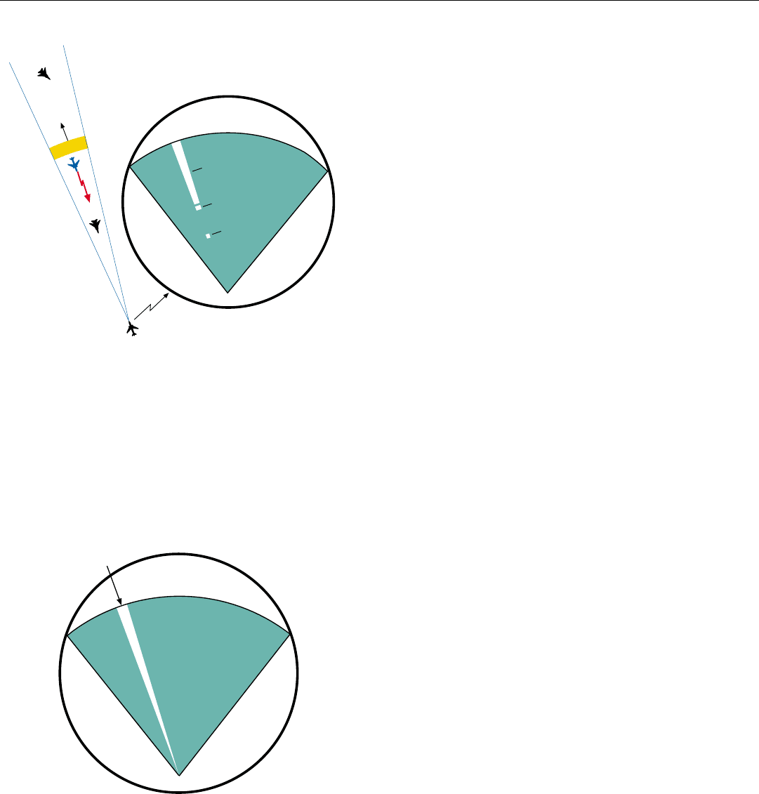
The first is to quickly tune the jammer to the frequency
of the last received pulse. The jamming then will mask the
returns from targets at greater ranges than the jammer from
the radar (Fig. 1). But it cannot mask the jamming aircraft
itself or targets at shorter ranges.
The enemy’s second option is to use barrage jamming—
i.e., spread the jammer’s power throughout the entire
band of frequencies over which the radar happened to be
operating or, in the case of a simple preset jammer, is
known to be capable of operating. The jamming then will
similarly mask the weak returns from long-range targets.
But, if the jammer is in a stand-off position, unless the
jamming is extremely powerful, it generally will be spread
so thin that the returns from shorter-range targets would
burn through.
In a coherent radar, however, frequency agility is of lim-
ited value in countering jamming. For a coherent radar’s
ability to perform predetection integration depends upon
the operating frequency remaining constant throughout the
integration period, which frequently is comparatively long.
A fast-set-on jammer can concentrate its power at the radar’s
frequency during virtually all of this period.
Detection and Angle-Tracking on the Jamming. Although
coherent radars cannot easily avoid noise jamming, they
can exploit it. Early on, a mode—variously called angle-on
jamming (AOJ), jam angle track (JAT), and angle track-on jam-
ming (ATOJ)—was provided which is still implemented in
radars today.
In this mode, the radar’s automatic detection function is
adjusted so that the jamming produces a bright line, or
strobe, on the radar display as the antenna scans across the
jammer in search (Fig. 2). By observing the strobe, the
operator can determine the jamming aircraft’s direction and,
by locking the radar onto the jamming, track the aircraft in
angle.
By then launching IR-guided missiles or radar-guided
missiles capable of homing in on the jamming, a feature
called home-on jamming (HOJ), the pilot has a good chance
of shooting the aircraft down.
But, to avoid blindly wasting missiles, by launching
them at too long a range, or unnecessarily extending the
attack and increasing the risk of getting shot down, the
crew of the launch aircraft must at least have a rough idea
of the target’s range. One way of obtaining that is through
passive ranging.
1. By changing its operating frequency from pulse to pulse, a
noncoherent radar can keep a jamming aircraft from masking
both itself and targets at shorter ranges. But it cannot keep the
jammer from masking targets at longer ranges.
2. In angle-on jamming, as the radar beam scans across a jam-
ming aircraft in search, the jamming produces a bright line
(strobe) on the radar display in the jammer’s direction.
Radar Display
Radar
Pulse
Jamming
Aircraft
Target
Long-Range Target
Jamming
Short-Range
Target
Jamming Aircraft
Jamming
Jamming
Strobe
Radar Display
