George W. Stimson introduction to Airborne Radar (Se)
Подождите немного. Документ загружается.

469
Electronic Warfare
Intelligence Functions
W
ith the continual advances in radar tech-
nology and the increasing complexity of
aerial combat, the effectiveness of ECM
and ECCM has become increasingly
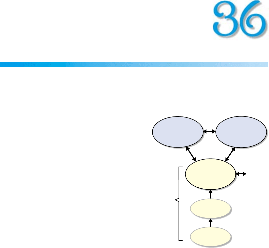
dependent on three levels of intelligence:
• Knowledge of the capabilities and operating parame-
ters of hostile systems which may be encountered—
what’s potentially out there
• Knowledge of the electronic order of battle (EOB) of
the hostile force about to be engaged—what’s out there
today and where
• Real-time threat warning—what’s after me now
Answers to these questions are provided by ELINT, ESM,
and the RWR, respectively. This chapter briefly introduces
them and explains what functions they perform.
Electronic Intelligence (ELINT)
ELINT is the gathering of information on the radars and
associated electronics of potential hostile threats. It is typi-
cally performed by government intelligence agencies. The
continually gathered data from various sources—including
both human agents and sensitive radio receivers—is thor-
oughly analyzed and used as a basis for the design of ESM
systems.
Electronic Support Measures (ESM)
Carried in certain tactical aircraft ESM, systems are
designed to collect, in advance, information on the elec-
ECM ECCM
RWR
Disable or impair
performance of enemy
radars.
Circumvent or other-
wise defeat enemy
ECM.
• Detect RF emissions.
• Identify their sources.
• Determine optimum
responses.
Radar
& other
onboard
resources
ESM
ELINT
What’s out there
today
and where.
What’s after
me
now!
What’s
potentially
out there.
Intelligence
Functions
Collect information
on the EOB
Provide data on
hostile systems
PART VIII Radar in Electronic Warfare
470
tronic order of battle (EOB) for the radar warning receivers
(RWRs) and flight crews of the aircraft about to be
deployed on a mission.
In essence, the ESM system performs three main func-
tions: (1) detects the enemy’s RF emissions; (2) measures
their key parameters; (3) from them, identifies the sources
of the emissions.
Detecting RF Emissions. Combat aircraft may encounter
threats over a broad spectrum of radio frequencies. The
ESM system must cover all of it, yet have the RF selectivity
to separate simultaneously received signals that are closely
spaced in frequency. In the past, this difficult combination
of requirements was satisfied with scanning superhetero-
dyne receivers, which are comparatively slow.
Today, the requirements are satisfied much more rapidly
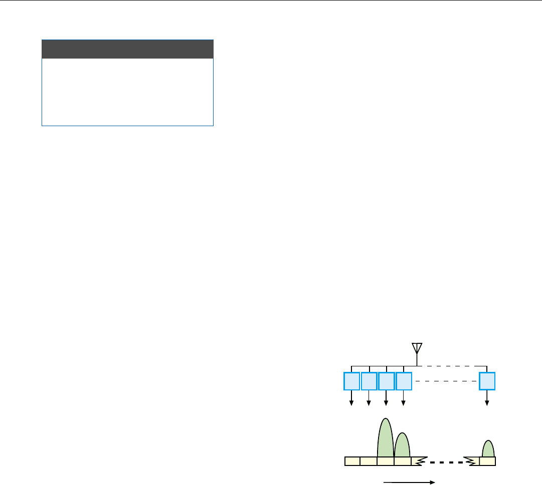
through channelization, that is, by dividing the spectrum to
be monitored into a great many partially overlapping chan-
nels
1
(Fig. 2). Each channel is made wide enough to accom-
modate the spectra of extremely short pulses, with enough
margin to enable accurate measurement of their times and
angles of arrival, yet narrow enough to separate individual
signals.
2
BASIC ESM FUNCTIONS
• Detect enemy’s RF emissions
• Measure their parameters
• Identify their sources
1. For economy, though, a
smaller number of wider
channels may be used.
2. Which entails providing
wideband antenna and other
RF hardware.
Receiver
Channels
Frequency
Channel
Widths
12 3 4 N
1234
N
Antenna
2. With channelization, the spectrum to be monitored is divided
into partially overlapping channels, each just wide enough to
pass the spectra of very short pulses with sufficient margin to
enable measurement of time of arrival and angle of arrival.
Most of the radars whose radiation the ESM system must
detect will have their antennas trained on the aircraft carry-
ing the system only fleetingly. Consequently, the ESM
receivers must be sensitive enough to detect even very weak
sidelobe emissions. Hundreds of radars, therefore, may be
within the system’s detection range at any one time.
Considering that some of these radars may be operating at
high PRFs—a vast number of pulses and other signals may
be received from all directions. So that their sources may be
identified, every received signal—be it a short pulse or a
continuous wave—must be individually detected.
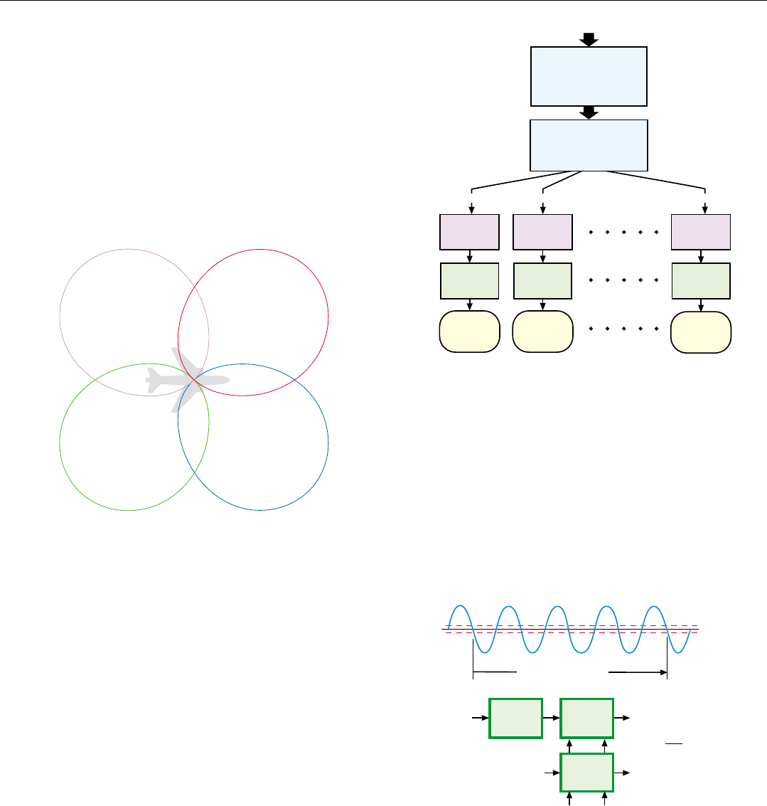
Extracting Key Signal Parameters. The principal steps
in extracting the parameters of the detected signals are out-
lined in Fig. 3. The first step is to record their times of
arrival (TOA) and measure their angles of arrival (AOA)
and radio frequencies (RF).
The angles of arrival may be measured virtually instanta-
neously by either of two methods. One is to provide a sepa-
rate antenna and receiving system for each quadrant in
azimuth and to sense the difference in amplitude of each
signal as received by the four antennas (Fig. 4).
CHAPTER 36 Electronic Warfare Intelligence Functions
471
Counting Interval, T
f =
N
2T
Signal
Clock Pulses
Timing
Strobe
Interval
Select
N
T
Selectable
Delay
Zero
Crossing
Counter
Interval
Counter
MEASURE
• Time of Arrival (TOA)
• Angle of Arrival (AOA)
• Radio Frequency (RF)
Received Signals
DE-INTERLEAVE
Sort Signals By
• AOA
Measure
Key
Parameters
Identify
Source Of
Signal #1
With
Threat Table
Compare
Measure
Key
Parameters
Identify
Source Of
Signal #2
With
Threat Table
Compare
Measure
Key
Parameters
Identify
Source Of
Signal #N
Compare
With
Threat Table
• RF • PRF*
*
From TOA
Signal #1 Signal #2 Signal #N
4. One way to instantaneously measure a signalís angle of arrival
(AOA): sense the difference in amplitude of the outputs it pro-
duces from four antenna beams.
3. Steps the ESM system takes to extract the key parameters of
the signals it detects and characterize their sources.
5. Innovative approach to instantaneously measuring the radio
frequency of a received signal. Number, N, of signal’s zero
crossings in interval, T, is counted and divided by 2T.
Selectable delay compensates for short time it takes to detect
signal and generate a timing strobe.
3. Pulse width is difficult to
measure accurately; for reflec-
tions may be received from
the ground which are stag-
gered relative to the directly
received pulses.
The other method is to place three or four antennas in
each quadrant and to sense the difference in phase of each
signal as received by the individual antennas.
Frequency also may be measured instantaneously. Coarse
frequency is determined from the channel the signal is
received through. Fine frequency may then be determined
by a frequency discriminator or a special instantaneous fre-
quency-measurement circuit (IFM), such as is illustrated in
Fig. 5 in the output of each channel. Less sophisticated sys-
tems may instead make the fine measurements with a scan-
ning narrowband superheterodyne receiver in each chan-
nel.
By sorting the signals according to angle of arrival, fre-
quency, and PRF (obtained from the recorded times of
arrival), the ESM system quickly separates—“de-inter-
leaves”—the signals received from different sources. It then
precisely measures key parameters—such as interpulse
modulation, intrapulse modulation (pulse compression
coding), beam width, scan rate, polarization, and pulse
width
3
—of the signals from each source.
PART VIII Radar in Electronic Warfare
472
Identifying the Sources. Finally, by comparing the mea-
sured signal parameters with the parameters of all known
threats, stored in “threat tables,” the ESM system identifies
each source. For mobile surface-based threats, the system
also determines current location. These data, together with
ELINT data, enable the mission to be planned to avoid
unnecessary exposure to lethal threats.
If the ESM system detects previously unknown wave-
forms or variations of known waveforms it stores the mea-
sured parameters for post-flight analysis and subsequent
permanent entry into the threat tables of the radar warning
receivers.
Radar Warning Receiver (RWR)
As a rule, RWRs are less comprehensive and far more
numerous than the ESM systems. Intended primarily to
warn the air crew of imminent attack, they generally are
sensitive only to the mainlobe emissions of systems track-
ing the aircraft.
Much as in an ESM system, the RWR detects these emis-
sions and identifies the threats they represent by comparing
their characteristics with those stored in a threat table. It
then evaluates and prioritizes the threats. Through expert
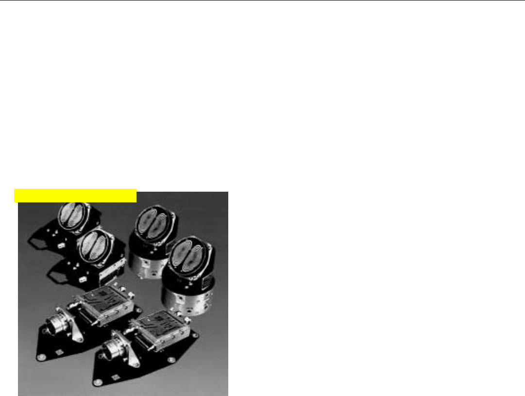
systems techniques, the modern RWR (Fig. 6) may even
determine the optimum responses to be made by the pilot
and/or the appropriate electronic combat (EC) systems—
radar, ECM, ECCM, IR search track set, FLIR, etc. The
RWR may also control the timing and execution of the EC
responses under close oversight of the air crew who are
alerted to the RWR’s actions and can override any of them.
Summary
Effective employment of both ECM and ECCM depends
on the ability of (a) ELINT to determine the capabilities of
the radars of potential hostile forces, (b) the ESM system to
determine the electronic order of battle, and (c) the ability
of the RWRs in the individual aircraft to detect the RF emis-
sions of any enemy system that threatens the aircraft, iden-
tify the sources of the emissions, and determine optimum
responses.
6. While most RWRs are comparatively simple, an advanced
RWR, such as the ALR-67 V3/4, may perform virtually all of
the functions of a highly capable ESM system.
Click for high-quality image
473
Electronically Steered
Array Antennas (ESAs)
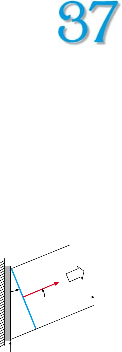
1. The ESA is mounted in a fixed position on the airframe. Its
beam is steered by individually controlling the phase of the
waves transmitted and received by each radiating element.
E
lectronically steered array antennas, ESAs, have
been employed in surface based radars since the
l950s.
1
But, because of their greater complexity
and cost, they have been slow to replace mechani-
cally steered antennas in airborne applications.
However, with the advent of aircraft of extraordinarily
low radar cross section and the pressing need for extreme
beam agility, in recent years avionics designers have given
the ESA more attention than virtually any other “advanced”
radar concept.
In this chapter, we will briefly review the ESA concept,
become acquainted with the two basic types of ESAs, and
take stock of the ESA’s many compelling advantages, as well
as a couple of significant limitations.
Basic Concepts
An ESA differs from the conventional mechanically
steered array antenna in two fundamental respects:
• It is mounted in a fixed position on the aircraft struc-
ture
• Its beam is steered by individually controlling the
phase of the radio waves transmitted and received by
each radiating element (Fig. 1)
A general purpose digital processor, referred to as the
beam steering controller (BSC) translates the desired deflec-
tion of the beam from the broadside direction (normal to
the plane of the antenna) into phase commands for the
individual radiating elements.
The incremental phase difference, ∆φ, which must be
applied from one radiating element to the next to deflect
θ
Broadside
Direction
Wavefront*
*Line of equal phase radiation
Radiating
Elements
ESA
θ
Airframe Structure
1. In surface-based radars, they
were called “phased arrays”—
a name which has carried over
to airborne applications. They
are frequently called electroni-
cally “scanned,” as opposed to
“steered” arrays. In light of the
versatility of the technique,
the more general “steered” is
used here.
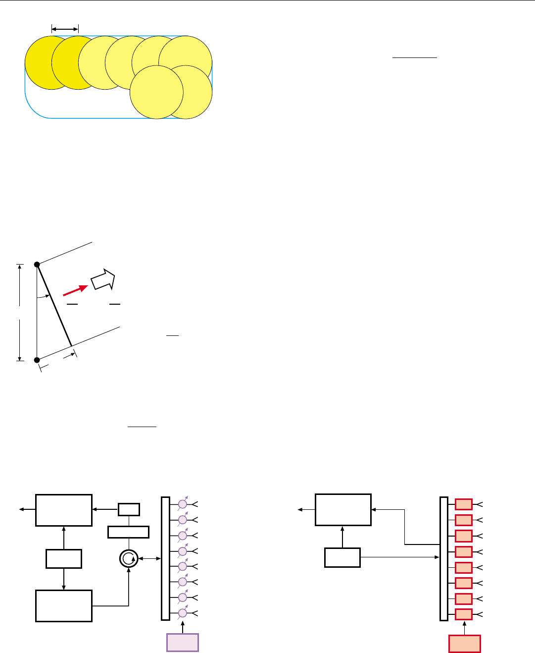
3. The passive ESA uses the same central transmitter and receiv-
er as the MSA. Its beam is steered by placing an electronical-
ly controlled phase shifter immediately behind each radiating
element.
4. In the active ESA, a tiny transmit/receive (T/R) module is
placed immediately behind each radiating element. The cen-
tralized transmitter, duplexer, and front-end receiving ele-
ments are thereby eliminated.
PART IX Advanced Concepts
474
the beam by a desired angle,
θ
, is proportional to the sine
of
θ
(see panel, left center).
∆φ =
2π d sin
θ
λ
where d is the element spacing and λ is the wavelength.
For search, the beam is scanned by stepping it in small
increments from one position to the next (Fig. 2), dwelling
in each position for the desired time-on-target, t
ot
. The size
of the steps—typically on the order of the 3-dB beam
width—is optimized by trading off such factors as beam
shape loss and scan frame time.
Types of ESAs
ESAs are of three basic types: passive, active, and a vari-
ant of the active ESA, called the true-time-delay (TTD) ESA.
Passive ESA. Though considerably more complex than a
mechanically steered array (MSA), the passive ESA is far
simpler than the active ESA. It operates in conjunction with
the same sort of central transmitter and receiver as the
MSA. To steer the beam formed by the array, an electroni-
cally controlled phase shifter is placed immediately behind
each radiating element (Fig. 3, below left), or each column
of radiating elements in a one-dimensional array. The phase
shifter is controlled either by a local processor called the
beam steering controller (BSC) or by the central processor.
Active ESA. The active ESA is an order of magnitude
more complex than the passive ESA. For, distributed within
it, are both the transmitter power-amplifier function and
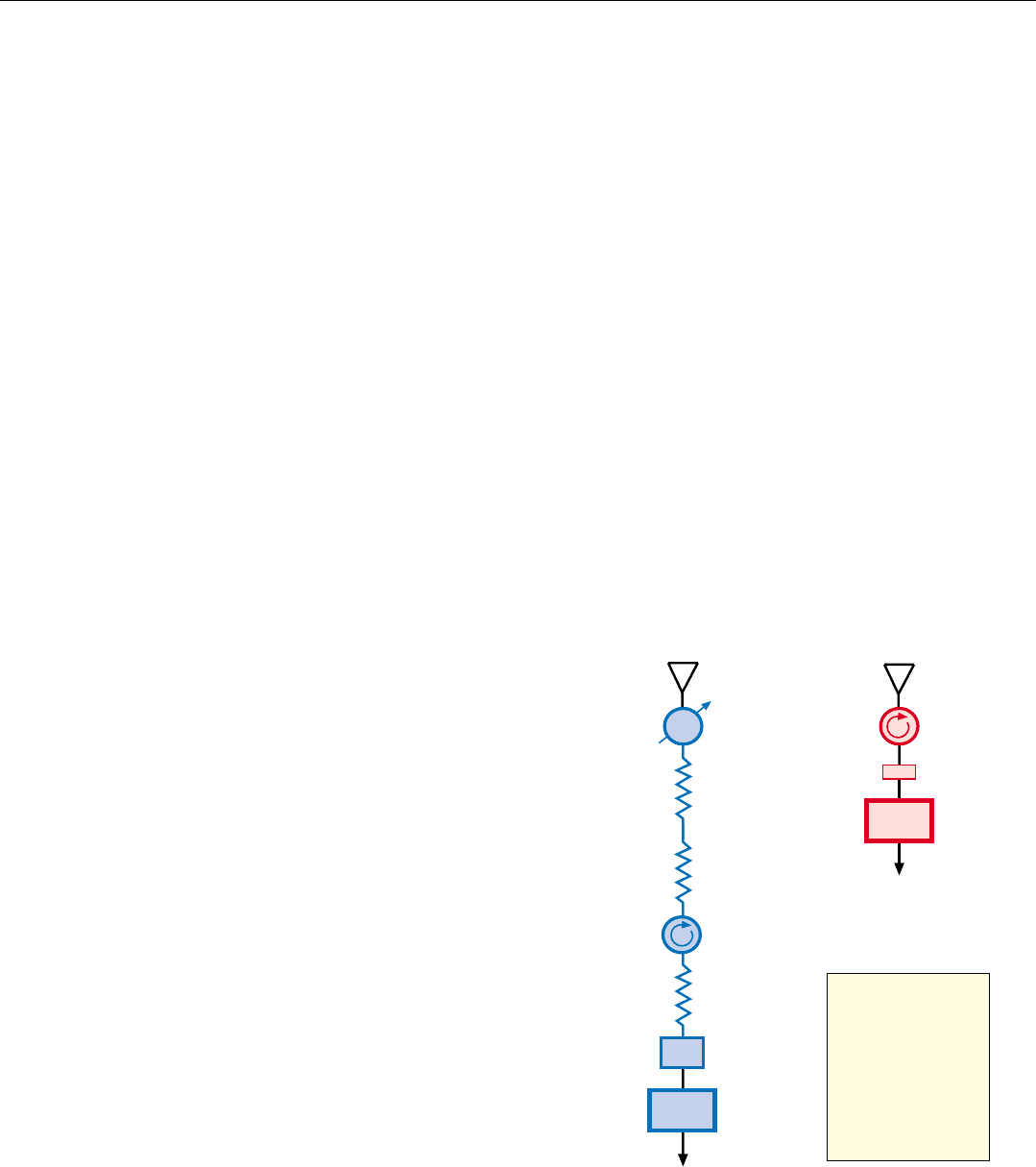
the receiver front-end functions. Instead of a phase shifter, a
tiny dedicated transmit/receive (T/R) module is placed
directly behind each radiating element (Fig. 4).
2. For search, the beam steps ahead in increments nominally
equal to the 3-dB beamwidth, dwelling in each position for a
period equal to the desired time-on-target.
φ
φ
φ
φ
φ
φ
φ
φ
PASSIVE ESA
The beam steering controller (BSC) function
may be performed in the central processor.
Receiver
Exciter
BSC
Duplexer
LNA
Protection
F
E
E
D
Transmitter
Scan Frame
3-dB Beamwidth
ACTIVE ESA
Receiver
Exciter
BSC
T/R
T/R
T/R
T/R
T/R
T/R
T/R
T/R
F
E
E
D
phase lag, ∆φ, that is incurred
in traveling the distance,
∆R,
from radiator B.
In traveling one wavelength
(λ) a wave incurs a phase lag
of 2
π radians. So, in traveling
the distance
∆R, it incurs a
phase lag of
As can be seen from the
diagram,
∆φ = 2 π
d sin
λ
Radiating
Elements
A
B
θ
θ
d
Broadside
To steer the beam
degrees off broadside, the phase of the
excitation for element B must lead that for element A by the
Hence, the element-to-element phase difference needed
to steer the beam q radians off broadside is
∆R
Line of Equal Phase Radiation
θ
θ
PHASE SHIFT NEEDED TO STEER THE BEAM
θ
2 π
∆R
λ
radians
∆R = d sin
θ
CHAPTER 37 Electronically Steered Array Antennas (ESAs)
475
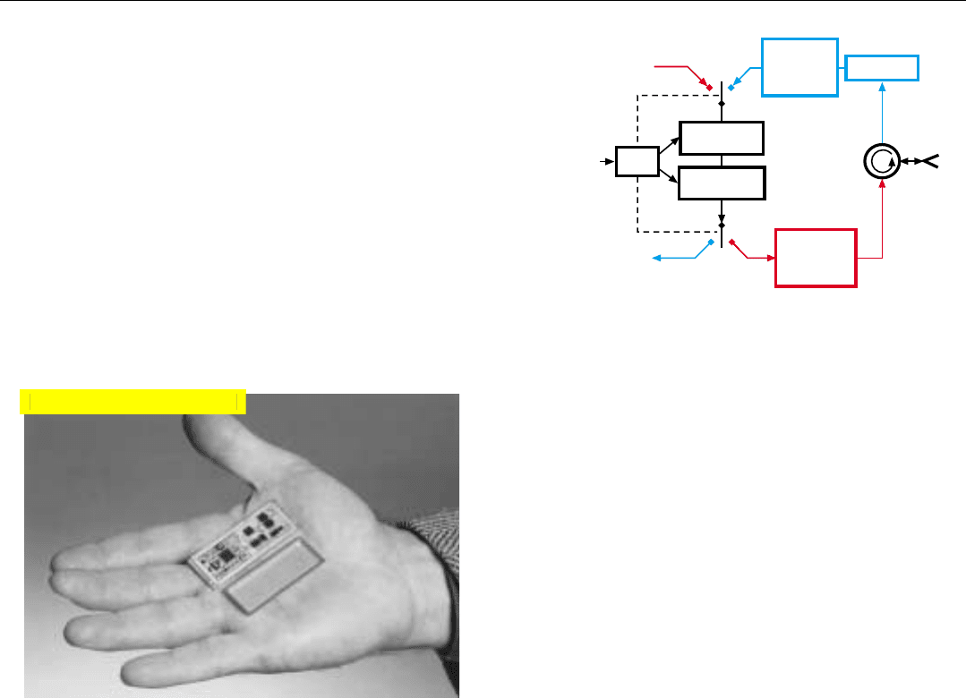
5. Basic functional elements of a T/R module. Variable gain
amplifier, variable phase shifter, and switches are controlled
by the logic element. They may be duplicated for transmit
and receive, or time shared as shown here.
This module (Fig. 5) contains a multistage high power
amplifier (HPA), a duplexer (circulator), a protection circuit
to block any leakage of the transmitted pulses through the
duplexer into the receiving channel, and a low-noise pre-
amplifier (LNA) for the received signals. The RF input and
output are passed through a variable gain amplifier and a
variable phase shifter, which typically are time shared
between transmission and reception. They, and the associat-
ed switches, are controlled by a logic circuit in accordance
with commands received from the beam steering controller.
To minimize the cost of the T/R modules and to make
them small enough to fit behind the closely spaced radia-
tors, the modules are implemented with integrated circuits
and miniaturized (Fig. 6).
Logic
T/R MODULE
Variable
Phase Shifter
Variable
Gain Amplifier
From Exciter
From
BSC
Protection
R
Low-Noise
Amplifier
(LNA)
To Receiver
T
R
Radiator
Duplexer
High-Power
Amplifier
(HPA)
T
6. A representative T/R module. Even a fairly small ESA would
include two to three thousand such modules.
TTD ESA. This is an active ESA in which the phase
shifts for beam steering are obtained by varying the physi-
cal lengths of the feeds for the individual T/R modules.
Drawing on the photonic techniques that have proved so
valuable in communications systems, a fiber-optic feed is
provided for each module. The time delay experienced by
the signals in passing through the feed—hence their
phase—is controlled by switching precisely cut lengths of
fiber into or out of the feed. By avoiding the limitations on
instantaneous bandwidth inherent in electronic phase shift-
ing, the photonic technique makes possible extremely wide
instantaneous bandwidths.
Since TTD is still in its infancy, it will be described in
Chap. 40, Advanced Radar Techniques, rather than here.
Advantages Common to Passive and Active ESAs
Both passive and active ESAs have three key advantages
which have proved to be increasingly important in military
aircraft. They facilitate minimizing the aircraft’s RCS. They
enable extreme beam agility. And they are highly reliable.
Click for high-quality image
PART IX Advanced Concepts
476
Facilitating RCS Reduction. In any aircraft which must
have a low RCS, the installation of a radar antenna is of
critical concern. For even a comparatively small planar
array can have an RCS of several thousand square meters
when illuminated from a direction normal to its face (i.e.,
broadside). With an MSA, which is in continual motion
about its gimbal axes, the contribution of antenna broad-
side reflections to the aircraft’s RCS in the threat window of
interest cannot be readily reduced. With an ESA, which is
fixed relative to the aircraft structure, it can be. How that is
done is explained in Chap. 39.
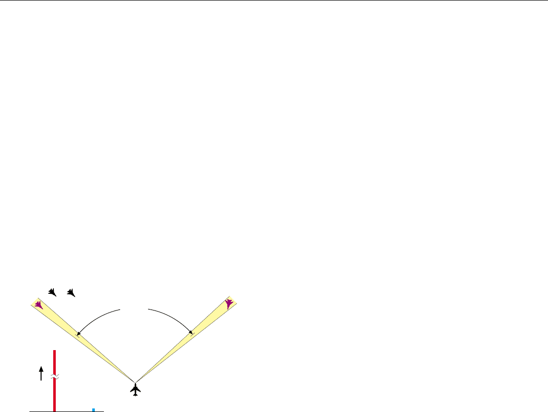
Extreme Beam Agility. Since no inertia must be over-
come in steering the ESA’s beam, it is far more agile than
the beam of an MSA. To appreciate the difference, consider
some typical magnitudes. The maximum rate at which an
MSA can be deflected, hence the agility of its beam, is limit-
ed by the power of the gimbal drive motors to between 100
and 150 degrees per second. Moreover, to change the direc-
tion of the beam’s motion takes roughly a tenth of a second.
By contrast, the ESA’s beam can be positioned anywhere
within a ±60 degree cone (Fig. 7) in less than a millisecond!
This extreme agility has many advantages. It enables:
• Tracking to be established the instant a target is
detected
• Single-target tracking accuracies to be obtained
against multiple targets
• Targets for missiles controlled by the radar to be illu-
minated or tracked by the radar even when they are
outside its search volume
• Dwell times to be individually optimized to meet
detection and tracking needs
• Sequential detection techniques
2
to be used, signifi-
cantly increasing detection range
• Terrain-following capabilities to be greatly improved
• Spoofing to be employed anywhere within the anten-
na’s field of regard
These capabilities have given rise to a whole new, highly
versatile and efficient approach to allocating the radar front-
end and processing resources and to controlling and inter-
leaving the radar’s various modes of operation (see Chap. 41).
High Reliability. ESAs are both reliable and capable of a
large measure of graceful degradation. They completely
eliminate the need for a gimbal system, drive motors, and
rotary joints—all of which are possible sources of failure.
In a passive ESA, the only active elements are the phase
shifters. High quality phase shifters are remarkably reliable.
7. To jump the antenna beam from one to another of two targets
separated by 100°, an MSA would take roughly a second.
An ESA could do it in less than a millisecond.
ESAMSA
Time
1 second
< 1 millisecond
100°
2. Such as alert-confirm detec-
tion. See Chap. 40.
Moreover, if they fail randomly, as many as 5% can fail
before the antenna’s performance degrades enough to war-
rant replacing them.
The active ESA yields an important additional reliability
advantage by replacing the central transmitter with the T/R
modules’ HPAs. Historically, the central TWT transmitter
and its high-voltage power supply have accounted for a
large percentage of the failures experienced in airborne
radars. The active ESA’s T/R modules, on the other hand,
are inherently highly reliable. Not only are they implement-
ed with integrated solid-state circuitry, but they require
only low-voltage dc power.
In addition, like the phase shifters of the passive ESA, as
many as 5% of the modules can fail without seriously
impairing performance. Even then, the effect of individual
failures can be minimized by suitably modifying the radia-
tion from the failed element’s nearest neighbors. As a result,
the mean time between critical failures (MTBCF) of a well
designed active ESA may be comparable to the lifetime of
the aircraft!
Additional Advantages of the Active ESA
The active ESA has a number of other advantages over
the passive ESA. Several of these accrue from the fact that
the T/R module’s LNA and HPA are placed almost immedi-
ately behind the radiators, thereby essentially eliminating
the effect of losses not only in the antenna feed system but
also in the phase shifters.
• Neglecting the comparatively small loss of signal
power in the radiator, the duplexer, and the receiver
protection circuit, the net receiver noise figure is
established by the LNA (Fig. 8). It can be designed to
have a very low noise figure.
• Loss of transmit power is similarly reduced. This
improvement, though, may be offset by the difference
between the modules’ efficiency and the potentially
very high efficiency of a TWT.
• Amplitude, as well as phase, can be individually con-
trolled for each radiating element on both transmit
and receive, thereby providing superior beam-shape
agility for such functions as terrain following and
short-range SAR and ISAR imaging.
• Multiple independently steerable beams may be radi-
ated by dividing the aperture into sub apertures and
providing appropriate feeds.
• Through suitable T/R module design, independently
steerable beams of widely different frequencies may
simultaneously share the entire aperture.
CHAPTER 37 Electronically Steered Array Antennas (ESAs)
477
8. By eliminating sources of loss ahead of the LNA, the active
ESA achieves a dramatic reduction in receiver noise figure
over that obtainable with a comparable passive ESA.
Phase Shifter
Level 1 Feed
Level 2 Feed
Central
Duplexer
Waveguide
Central
Receiver
Protection
PASSIVE ESA
- 0.7 dB
- 0.8 dB
- 0.6 dB
- 0.25 dB
- 0.2 dB
- 0.5 dB
F
n
ACTIVE ESA
Noise Figure:
F
n
+ 0.25 dB
Noise Figure:
F
n
+ 3.05 dB
For both the passive
ESA and the active
ESA, the receiver
noise figure equals the
noise figure of the LNA
(F
n
) plus the total loss
of all elements ahead
of the LNA.
Loss Element
F
n
LNA
Duplexer
Low-Power
Receiver
Protection
- 0.15 dB
- 0.10 dB
Loss Element
LNA
NOTE
φ
PART IX Advanced Concepts
478
Key Limitations and Their Circumvention
Along with its many advantages, the ESA—whether
active or passive—complicates a radar’s design in two areas
which are handled relatively simply with an MSA: (a)
achieving a broad field of regard, and (b) stabilizing the
antenna beam in the face of changes in aircraft attitude.
These complications and the means for circumventing them
are outlined briefly in the following paragraphs.
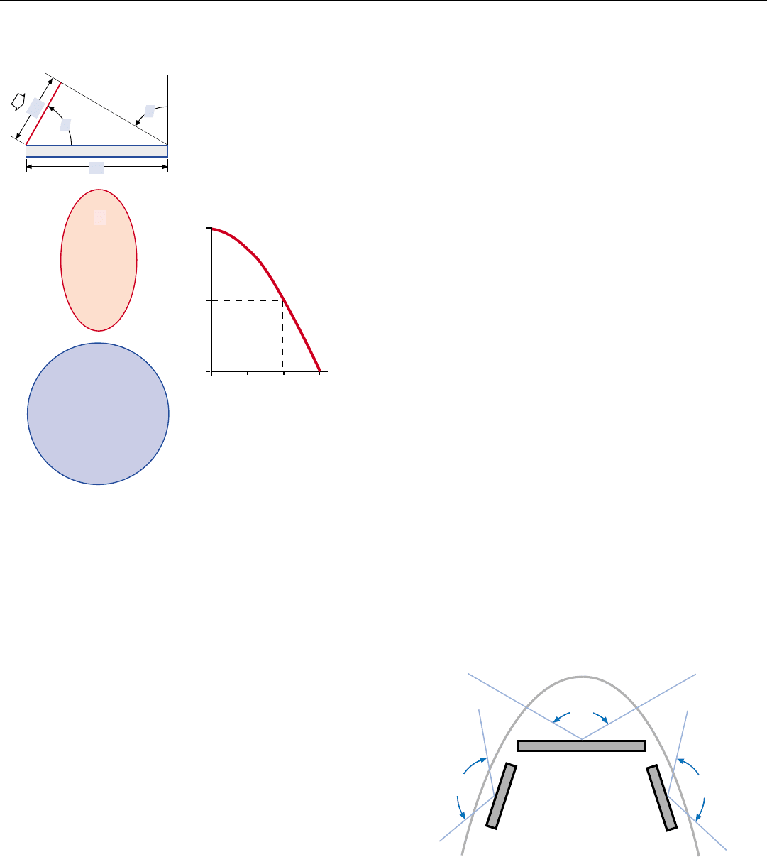
Achieving a Broad Field of Regard. With an MSA, to
whatever extent the radome provides unobstructed visibili-
ty, the antenna’s field of regard may be increased without in
any way impairing the radar’s performance. With an ESA,
however, as the antenna beam is steered away from the
broadside direction, the width of the aperture is foreshort-
ened in proportion to the cosine of the angle off broadside,
increasing the azimuth beam width (see panel, left)
.
More importantly, the projected area of the aperture also
decreases in proportion to the cosine of the angle, causing
the gain to fall off correspondingly. At large angles off
broadside, the gain falls off still further as a result of the
lower gain of the individual radiators at these angles.
Depending upon the application, the fall-off in gain may
be compensated to some extent by increasing the dwell
time—at the expense of reduced scan efficiency. Even so,
the maximum usable field of regard is generally limited to
around ±60°.
While ±60° coverage is adequate for many applications,
2
wider fields of regard may be desired. More than one ESA
may then be provided—at considerable additional expense.
In one possible configuration, a forward-looking main array
is supplemented with two smaller “cheek” arrays, extending
the field of regard on either side (Fig. 10).
Angle Off Broadside,
0306090°
1.0
0.5
0.0
A'
A
W' = W cos
As an ESA’s beam is steered
off broadside, width, W, of the
effective aperture foreshortens.
A' = A cos
Since the gain of the antenna
is proportional to the projected
area, the maximum practical
field of regard for an ESA is
limited to about ± 60°.
The foreshortening broadens
the beam. But more import-
antly, it reduces the projected
area, A', of the array, as view-
ed from angle, , off broadside.
Projected
area of array,
viewed from
angle off
broadside
A'
Area of array as
viewed from
broadside
A
W
θ
W'
LIMITATION ON FIELD OF REGARD
θ
θ
θ
θ
θ
θ
ESA
(
top view
)
9. Where a broad field of regard is desired, more than one ESA
may be used. Here, a central primary array is supplemented
with two smaller, “cheek” arrays providing short-range cover-
age on both sides, for situation awareness.
120°
PRIMARY ARRAY
120°
CHEEK ARRAY
120°
CHEEK ARRAY
2. In many applications, because
of radome restrictions, ±60˚ is
about all that can be obtained,
even with an MSA.
Beam Stabilization. With an MSA, beam stabilization is
not a problem. For the antenna is mounted in gimbals and
slaved to the desired beam-pointing direction in spatial
