George W. Stimson introduction to Airborne Radar (Se)
Подождите немного. Документ загружается.

PART IX Advanced Concepts
490
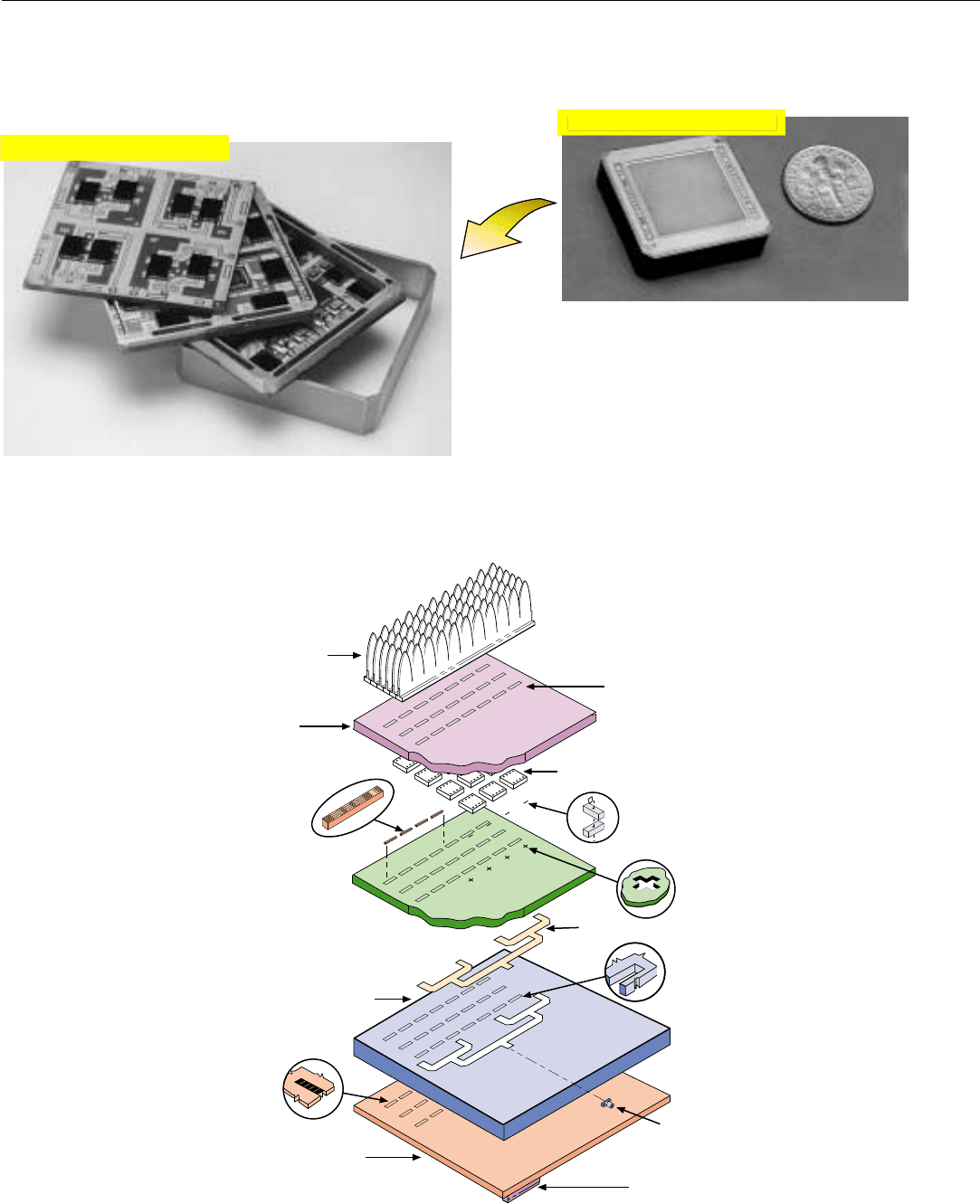
Another approach to the physical design of an active ESA
is a so called “tile” architecture. It employs dime-sized three-
dimensional, four-channel modules (Fig. 15).
15. Dime-sized four-channel, three-dimensional T/R module.
Within each module (Fig. 16), successive sections of four
T/R circuits are placed on three circuit boards, mounted
one on top of the other. Heat generated in the circuits on
each board is conducted to the surrounding metal frame.
The modules are sandwiched between cold plates having
feed-through slots for the RF signals, dc power, and control
signals (Fig. 17).
16. Within the module, successive sections of four T/R circuits are
placed on three boards, the heat from which is conducted out
to the surrounding metal frame.
17. “Tile” array architecture. Four-channel three-dimensional T/R modules (such as shown in Fig. 10) are sandwiched between two cold plates.
RF input and output signals, control signals, and dc-power feed through slots in the lower cold plate. RF signals to and from the radiators
feed through slots in the upper cold plate.
DC and
Control
Signal
Connector
Lower Cold Plate
Power and
Control-Signal
Distribution
Printed Wiring
Board.
RF Connector
Feed
Circuit
DC Power and
Control Signal
Feed Through
Coaxial
Connector
DC and Control
Signal Connector
DC Power and
Control Signal
Pads
Radiators
Upper
Cold
Plate
4-Channel T/R Tile Modules
RF Feed-Through
Cover
Enlarged
Click for high-quality image
Click for high-quality image
For sidelobe reduction, precise control of phase and gain
in each module is essential. Consequently, a comprehensive
automatic self-test and calibration capability is provided. To
account for manufacturing tolerances, the initial calibration
correction for each module is set into a nonvolatile memory
in the module’s control circuit.
Finally, since more than the maximum acceptable num-
ber of modules may malfunction during the operational life
of the aircraft, provisions must be included for removing
and replacing individual modules—a difficult design task,
to say the least.
Summary
To minimize the cost of an ESA—whether passive or
active—the radiating elements must be spaced as far apart
as possible without creating grating lobes. The maximum
spacing is about half a wavelength. For stealth, still closer
spacing may be required to avoid Bragg lobes.
The number of radiators may be reduced by up to 14%
by using a diamond lattice. And it may be reduced still fur-
ther by thinning the density of elements at the array’s edges,
but for such reductions, a price is paid in terms of sidelobe
and RCS performance.
Key elements of a passive ESA are the phase shifters.
They account for more than half the weight and cost of the
array, hence must be lightweight and low cost. Also critical
are the transmission lines and feed. For wideband opera-
tion, strip line and either a corporate or a space feed must
be used. For high power and weak-signal detection, hollow
waveguide is required.
The key element of an active ESA is the T/R module. It is
implemented with a limited number of monolithic integrat-
ed circuits in a hybrid microcircuit. For X-band frequencies
and higher, the monolithic circuits are made of gallium
arsenide. Critical electrical characteristics are the module’s
peak power output, precision of phase and amplitude con-
trol, receiver noise figure, and noise modulation of the
transmitted signal, which must be minimized through fil-
tering of the dc input power.
To minimize the antenna’s RCS, the radiators are mount-
ed on an extremely rigid back plane. The T/R modules are
mounted on cold plates, immediately behind the back
plane. Self-test and self-calibration capabilities are essential.
CHAPTER 38 ESA Design
491
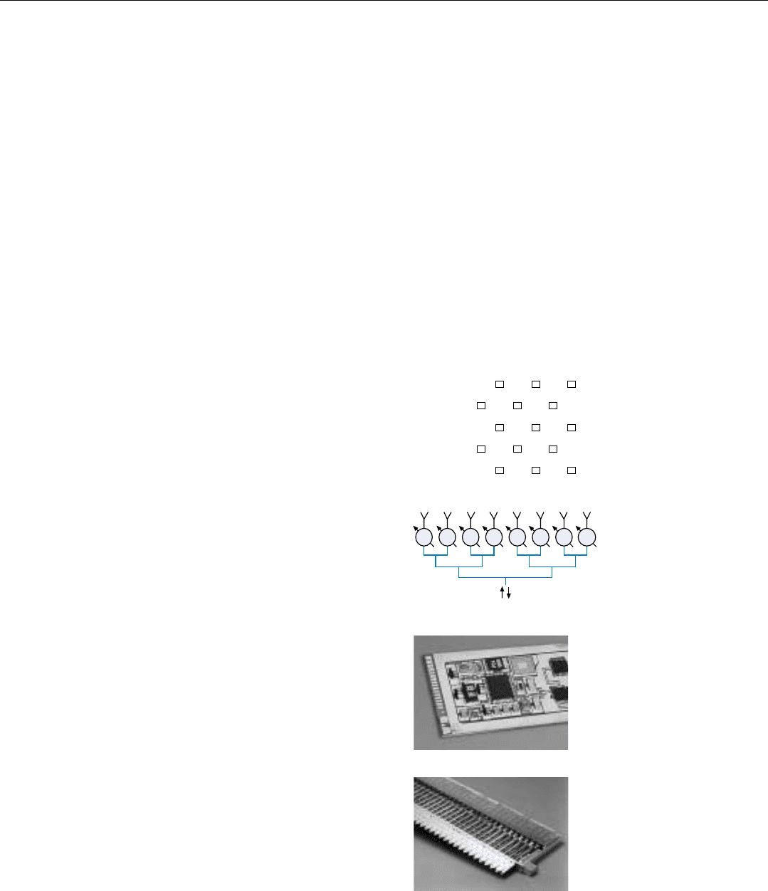
Diamond
Lattice
Corporate Feed
φφφφφφφφ
493
Antenna RCS
Reduction
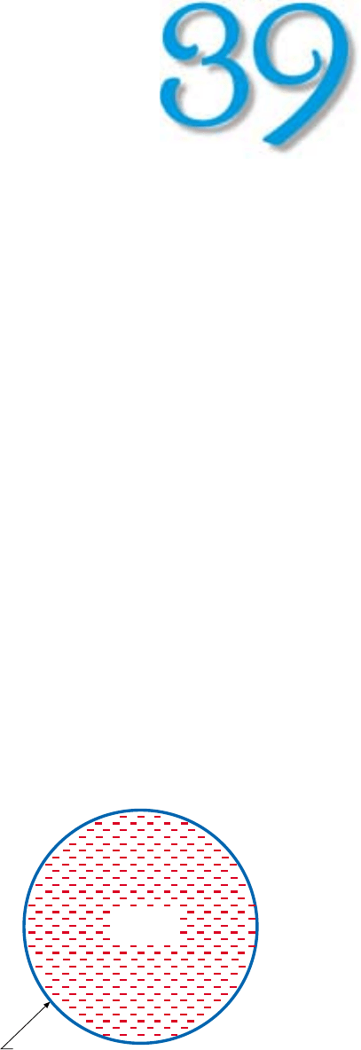
1. A planar array antenna, regardless of whether it is an
MSA or an ESA, can conveniently be though of as a flat
plate, termed the ground plane, containing a lattice of
radiating elements.
V
iewed nose-on, a typical fighter aircraft has a
radar cross section (RCS) on the order of one
square meter. A similarly viewed low observable
aircraft may have an RCS of only 0.01 square
meter. Unless special RCS reduction measures are
employed, even a comparatively small planar array antenna
can have an RCS of up to several thousand square meters
when viewed from a broadside direction! Since an aircraft’s
radome is transparent to radio waves, if stealth is required,
steps must be taken to reduce the RCS of the installed
antenna.
In this chapter, we will be introduced to the sources of
reflections from a planar array antenna, learn what can be
done to reduce or render them harmless, and see why these
steps are facilitated in an ESA.
We will then take up the problem of avoiding so-called
Bragg lobes, which are retrodirectively reflected at certain
angles off broadside if the radiator spacing is too large com-
pared to the radar’s operating wavelength.
Finally, we will very briefly consider the critically impor-
tant validation of an antenna’s predicted RCS.
Sources of Reflections from a Planar Array
For our purposes here, a planar array antenna, regardless
of whether it is an MSA or an ESA, can conveniently be
thought of as consisting of a flat plate—referred to as the
“ground plane”—containing a lattice of radiating elements
(Fig. 1).
The backscatter from the antenna when illuminated by a
radar in another aircraft—threat radar, we’ll call it—is com-
Ground Plane
Radiating
Elements
PART IX Advanced Concepts
494
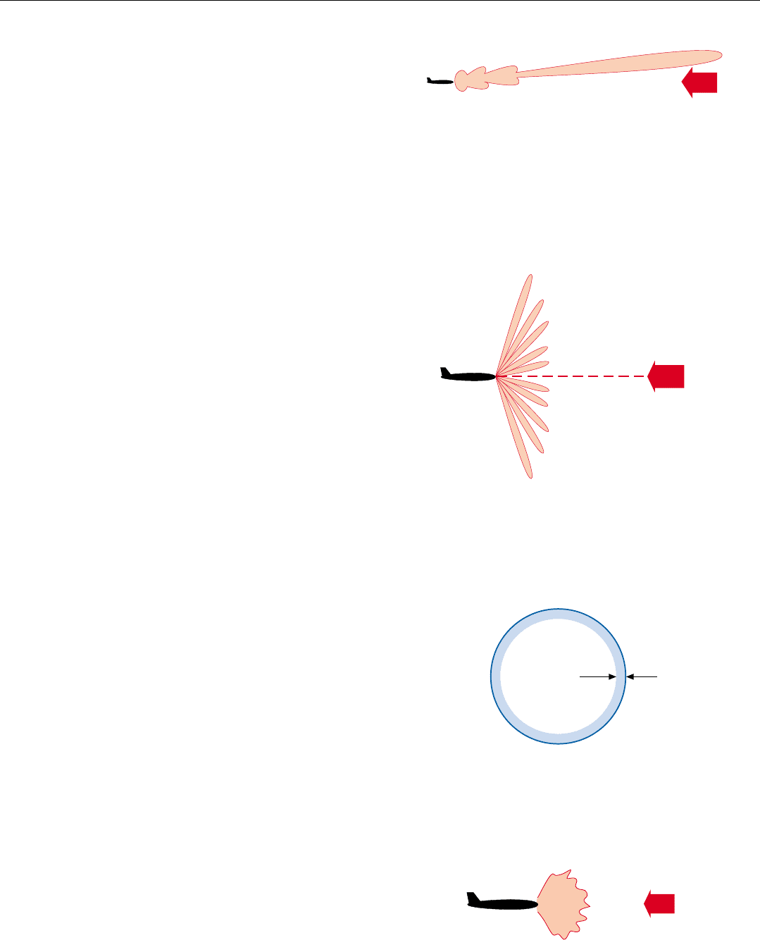
monly categorized as being comprised of four basic compo-
nents (Fig. 2).
1. Specular (mirrorlike) reflections from the ground
plane. These are called structural mode reflections.
2. Reflections of some of the received power by mis-
matched impedances within the antenna. Reradiated
by the radiating elements, these are called antenna
mode reflections.
3. Reflections due to the mismatch of impedances at the
edges of the array, i.e., between the ground plane and
the surrounding aircraft structure. These reflections
are referred to as edge diffraction.
4. Random components of the structural mode and
antenna mode reflections. These components are
called random scattering.
In case you’re wondering, there are two reasons for sepa-
rately breaking out random scattering.
First, with the random scattering removed, the structur-
al-mode and antenna-mode reflections can be characterized
more simply.
Second, there is then a one-to-one relationship between
the individual categories of reflections and the techniques
for reducing or controlling them.
Reducing and Controlling Antenna RCS
By carefully designing and fabricating an antenna, each
of the four components of backscatter may be acceptably
minimized or rendered harmless.
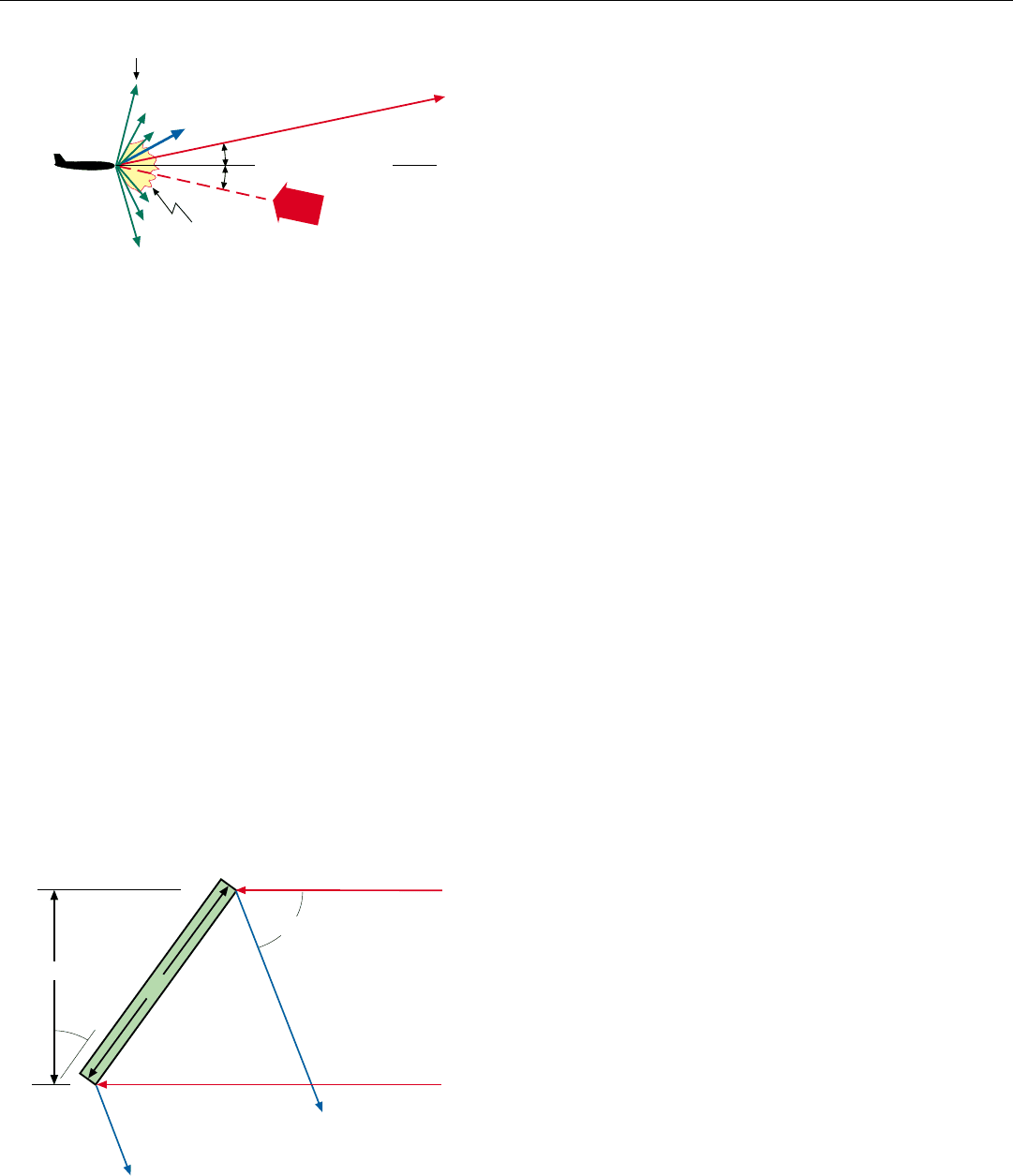
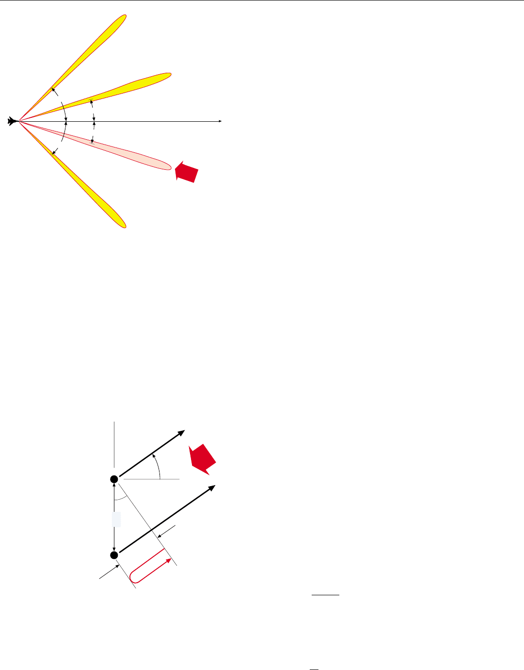
Rendering Structural Mode Reflections Harmless. As
may be seen from Fig. 3, these mirrorlike reflections may be
controlled by physically tilting the antenna so that they are
not directed back in the direction from which the illuminat-
ing radiation came. Although the tilt does not reduce the
reflections, it prevents the threat radar from receiving them.
With an ESA, which is mounted in a fixed position in
the aircraft, the antenna ground plane can be permanently
tilted so that the incident radiation will be harmlessly
reflected in the same direction as the irreducible “spike” in
the pattern of reflections from the aircraft structure. The tilt
reduces the antenna’s effective aperture area somewhat,
reducing the gain and broadening the beam about the axis
of the tilt. But this is a small price to pay for the huge
reduction in detectability that is achieved.
Minimizing Antenna Mode Reflections. At the radar’s
operating frequency, antenna mode reflections have a radia-
3. Structural mode reflections may be rendered harmless by tilting
the array. The tilt reduces the effective aperture somewhat but
that is a small price to pay for the huge reduction in detectabil-
ity achieved.
Rays of Radiation
From Threat Radar
Rays of Structural
Mode Reflections
D' = D cos
STRUCTURAL MODE REFLECTIONS
D
θ
θ
2
θ
2. The four basic components of backscatter from a planar
array antenna. Random scattering is the sum of the random
components of the structural-mode and antenna mode reflec-
tions.
θ
θ
Structural Mode
Reflections
Incident Radiation
from Threat Radar
Antenna Mode
Reflections
Edge
Diffraction
Random
Scattering
Broadside Direction
CHAPTER 39 Antenna RCS Reduction
495
6. Edge treatment must be at least four wavelengths wide.
Depending on the antenna’s size, this can seriously diminish
the effective aperture.
tion pattern similar to that of the transmitted signal: a main
lobe, surrounded by sidelobes (Fig. 4). The direction of the
main lobe is determined by the angle of incidence of the
illuminating waves and the element-to-element phase shift
occurring within the array. As is clear from the figure, these
reflections are not necessarily rendered harmless by the tilt
of the antenna.
They can be acceptably minimized, however, by employ-
ing well matched microwave circuitry in the antenna and
by paying extremely close attention to design detail. In
wideband MSAs and passive ESAs, even reflections from
deep within the antenna must be eliminated. This may be
accomplished by inserting isolators, such as circulators, at
appropriate points in the feed.
Minimizing Edge Diffraction. Edge diffraction produces
backscatter comparable to that which would be produced
by a loop antenna having the same size and shape as the
perimeter of the array. Since the dimensions of this loop are
generally many times the operating wavelength of the radar,
the radiation pattern of the loop typically consists of a great
many lobes fanning out from the broadside direction
(Fig. 5). Consequently, edge diffraction, too, is not rendered
harmless by the antenna’s tilt. Special measures must be
taken to minimize it.
In some antenna installations, edge diffraction is ren-
dered harmless by shaping the edge of the ground plane to
disperse the diffracted energy so that it is beneath the
threshold of detection of the threat radar.
In other installations, the diffraction is reduced by apply-
ing radar absorbing material (RAM) around the edges of the
ground plane so that its resistivity smoothly tapers to that
of the surrounding structure. To be effective, the treatment
must be at least four wavelengths wide at the lowest threat
frequency (Fig. 6). Consequently, it can seriously diminish
the available aperture area, and so reduce the radar’s perfor-
mance. Accordingly, careful tradeoffs are necessary between
radar performance and RCS performance.
In any event, the measures taken to reduce or render the
diffraction harmless are greatly facilitated in an ESA, since it
is permanently mounted in a fixed position on the aircraft
structure.
Minimizing Random Scattering. The random compo-
nents of structural mode and antenna mode reflections may
be spread over a wide range of angles (Fig. 7). So, they are
not rendered harmless by the antenna’s tilt. To reduce them
to acceptable levels, the antenna’s microwave characteristics
must be highly uniform across the entire array. This
requires exceptionally tight manufacturing tolerances.
4. Radiation pattern of these reflections is similar to that of trans-
mitted signal. Since their direction is determined by internal
phase shifts as well as by angle of incidence of illuminating
waves, they are not necessarily rendered harmless by tilt of
antenna.
5. Backscatter due to edge diffraction is comparable to that from
a loop the size and shape of the array’s perimeter. Since its
diameter is many times the operating wavelength, the
backscatter fans out in many directions.
Incident Radiation
from Threat Radar
EDGE DIFFRACTION
Incident Radiation
from Threat Radar
ANTENNA MODE REFLECTIONS
4 λ
At the lowest
threat frequency
7. The random components of structural mode and antenna
mode reflections are spread over a wide span of angles.
Incident
Radiation from
Threat Radar
RANDOM SCATTERING
PART IX Advanced Concepts
496
Avoiding Bragg Lobes
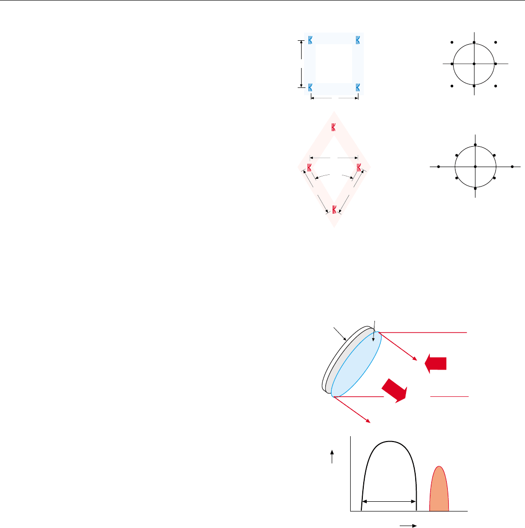
Bragg lobes are retrodirective reflections from the anten-
na’s radiators, which may be received by an illuminating
radar when it is in certain angular positions,
θ
n
, off broad-
side (Fig. 8). Depending on the antenna’s design, besides
direct reflections from the radiators, the lobes may also
include energy reflected from within the antenna (i.e.,
antenna-mode reflections).
The lobes are due to the periodicity of the radiator lat-
tice. They occur at those angles for which the phases of the
waves reflected in the illuminator’s direction by successive
radiators differ by 360° or multiples thereof, hence are all
in phase and add up to a strong signal.
While for simplicity Fig. 8 has been drawn for lobes in a
single plane, bear in mind that for a two-dimensional array
Bragg lobes occur about both lattice axes. As illustrated in
the panel below, the directions of the lobes relative to the
boresight direction are determined by the spacing of the
radiators relative to the wavelength of the illumination. The
greater the spacing and/or the shorter the wavelength, the
closer the lobes will be to the broadside direction and the
more lobes there will be.
8. Bragg lobes are retrodirective reflections which may be
received by an illuminating radar when it is a certain angle,
θ
n
, off broadside, if the spacing of the radiators is larger than
half the wavelength of the illumination.
To minimize the antenna’s RCS, the first
Bragg lobe (n = 1) must be placed 90° off
broadside (sin
1
= 1). Substituting these
values in the above equation yields:
d =
λ
2
When adjacent radiators of an array antenna
are illuminated by a threat radar, a Bragg lobe
will be produced if the wave reflected in the radar’s
direction (
n
) by the far radiator (B) is in phase
with the wave reflected by the near radiator (A).
Assuming no regular radiator-to-radiator phase
shift in reflections from within the antenna, that
condition will occur if the additional round-trip
distance, ∆R, traveled to and from radiator B is
a whole multiple, n, of the incident radiation’s
wavelength, λ.
∆R = 2 d sin
n
where d is the spacing between radiators.
Thus, the relationship between radiator
spacing and Bragg-lobe direction is
∆R = nλ
As is clear from the diagram ,
Incident Radiation
from Threat Radar
Radiator A
Radiator B
d
d sin
n
∆R = 2 d sin
n
CONDITIONS UNDER WHICH A BRAGG LOBE WILL BE PRODUCED
for stealth.
θ
θ
θ
θ
n
θ
n
θ
θ
d =
2 sin
n
n λ
θ
Incident
Radiation from
Threat Radar
Broadside
direction
Potential Lobe
Potential Lobe
Potential Lobe
A potential lobe materializes
if the antenna is illuminated by
a threat radar in the lobe’s
direction.
1
θ
1
θ
2
θ
2
θ
CHAPTER 39 Antenna RCS Reduction
497
Like grating lobes, Bragg lobes can be avoided by spacing
the radiators close enough together to place the first lobe
90° off broadside. As the panel shows, if the illumina
tor’s
wavelength is the same as the radar’s, this may be accom-
plished with a spacing of half the operating wavelength.
But, if the illuminator’s wavelength is shorter, the spacing
must be proportionately reduced. Suppose, for instance,
that the radar’s wavelength is 3 centimeters and the illumi-
nator is operating at 18 GHz (λ = 1.67 cm). To avoid Bragg
lobes, the radiator spacing would have to be reduced to
1.67 ÷ 2 = 0.84 centimeters—little more than a quarter of
the operating wavelength.
If such tight spacing is not economically feasible, the
designer has three options. The first two are comparatively
simple.
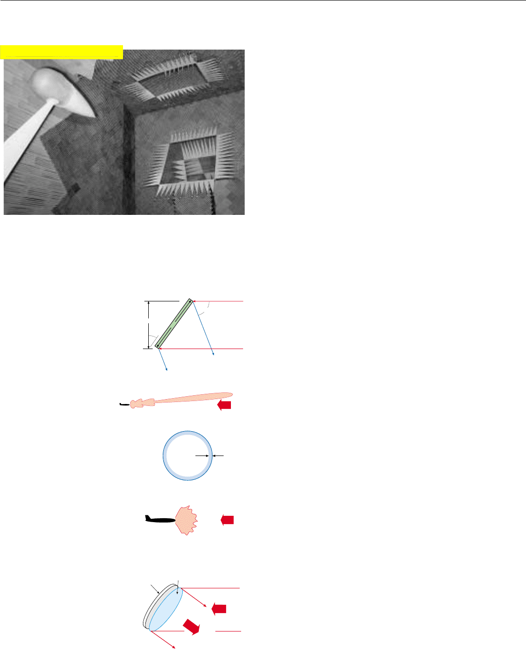
One is to use a diamond lattice such as that illustrated in
Fig. 9. Despite the larger radiator spacing of this lattice,
Bragg lobes may be rendered harmless.
The second option is simply to employ the tightest prac-
tical radiator spacing—at least along the axis of greatest
concern.
The third and more costly option is to prevent any short-
er wavelength radiation from reaching the array. One way of
accomplishing this is to place a frequency selective screen
(FSS) in front of the array (Fig. 10). The screen is designed
to pass all wavelengths in the radar’s operating band with
little attenuation, yet reflect all out-of-band radiation. The
screen may either be mounted externally as shown in Fig.
10 or be built into the antenna face. As with structural
mode reflections, because of the tilt of the antenna—hence
also of the screen—radiation reflected by the screen will be
directed in a nonharmful direction.
In one possible implementation, the screen consists of a
thin metal sheet containing a tight lattice of slots, mounted
between two dielectric slabs. To be effective, the slots must
be separated by no more than half the wavelength of the
highest threat frequency.
Validating an Antenna’s Predicted RCS
Because of the complexity of the factors contributing to
an antenna’s installed RCS, a key step in developing a low
RCS antenna is validating the antenna’s predicted RCS.
For this, one or more physical models of the radiating
aperture are generally built. These are called phenomenology
models, or “phenoms.” Typically, they include not only the
radiators and any covering that goes over them, but also the
first few stages of internal circuitry. If the schedule allows,
the phenoms may even be used to interactively refine the
design.
9. Bragg lobe patterns for square and 60° diamond radiator lat-
tices. Despite the greater radiator spacing of the diamond lat-
tice, all Bragg lobes except the central one are outside the
boundary of visible (real) space. The central lobe is rendered
harmless by the tilt of the antenna.
10. A frequency-sensitive screen acts as a bandpass filter, reject-
ing radiation of such high frequency that making the radiator
lattice tight enough to avoid grating lobes is not practical.
s
s
Square Lattice
s = 0.5263 λ
60°
60° Diamond
Lattice
s = 0.5656 λ
RADIATOR LATTICE BRAGG LOBES
In Sine Theta Space
s
s
s
Radar
Antenna
Frequency Sensitive
Screen (FSS)
Reflections
from screen
From
Threat
Radar
Frequency
Trans-
mission
Coef.
Radar’s
Total
Bandwidth
Frequency of
Threat Radar
PART IX Advanced Concepts
498
Measurements made on the phenoms, as well as on the
complete antennas, include the following:
• Closed circuit measurements at the radiator level to
isolate and quantify the complex reflections from each
radiator and its internal circuitry—commonly referred
to as “look-in” measurements.
• Angular “cuts” of the reflection pattern of the total
array.
• Very high resolution ISAR (inverse synthetic aperture
radar) images of the antenna, made to isolate individ-
ual reflection “hot spots” and to determine the effec-
tiveness of the edge treatment.
To realistically evaluate the installed antenna’s RCS, a
full-scale model of the nose section of the aircraft including
the phenom is generally tested in a large anechoic chamber
(Fig. 11).
Summary
Unless special measures are taken to reduce the reflec-
tions from a planar array, its RCS may be several thousand
square meters. The reflections are of four basic types, which
may be reduced or rendered harmless as follows:
• Mirror-like reflections from the back plane (structural
mode reflections)—may be rendered harmless by tilt-
ing the antenna.
• Reflections due to mismatched impedances within the
antenna (antenna mode reflections)—may be reduced
by minimizing the mismatches.
• Reflections due to mismatched impedances at the
edges of the array (edge diffraction)—may be reduced
by tapering the impedances with radar absorbing
material or shaping the edges of the ground plane to
disperse the diffracted energy.
• Random components of structural and antenna mode
reflections (random scattering)—may be reduced by
holding to extremely tight manufacturing tolerances.
To avoid retrodirective reflections from the radiator lat-
tice—Bragg lobes—the radiator spacing must be less than
half the wavelength of the illumination. If illuminators may
be encountered whose wavelengths are shorter than the
radar’s, either the radiator spacing must be further reduced,
or a frequency-sensitive screen must be placed over the
array to keep out the shorter wavelength radiation.
Because of the complexity of factors contributing to
antenna RCS, RCS predictions are validated with physical
models (phenoms), and a full-scale model of the nose sec-
tion is usually tested in an anechoic chamber.
11. The predicted RCS of the antenna for the radar of a fighter
aircraft is verified in an anechoic chamber. Antenna in its
radome is mounted on a low RCS test body.
Rays of Radiation
From Threat Radar
Rays of Structural
Mode Reflections
D' = D cos
STRUCTURAL MODE REFLECTIONS
D
θ
θ
2
θ
Incident Radiation
from Threat Radar
4 λ
At the lowest
threat frequency
Incident
Radiation from
Threat Radar
Radar
Antenna
Frequency Sensitive
Screen (FSS)
Reflections
from screen
From
Threat
Radar
ANTENNA MODE REFLECTIONS
RANDOM SCATTERING
Click for high-quality image

499
Advanced Radar
Techniques
T
he advent of active ESAs, the emergence of low
RCS aircraft, and the growing threat of electronic
countermeasures have given impetus to advanced
work in several key areas of radar technology.
This chapter, presents some significant developments
spawned by that work:
• Innovative approaches to multiple-frequency opera-
tion—for reducing vulnerability to countermeasures
and avoiding detection by the enemy
• Advanced signal integration and detection tech-
niques—for small target detection
• Bistatic modes of radar operation—for increasing sur-
vivability and for circumventing the limitation on
power-aperture product imposed by a tactical aircraft’s
small size
• Space-time adaptive processing—for efficiently reject-
ing external noise and jamming and compensating for
the motion-induced clutter spread with which long
range surveillance radars must contend
• True-time-delay beam steering—a technique still in its
infancy which promises to broaden the instantaneous
bandwidth of an active ESA sufficiently to enable
simultaneous shared use of the same antenna for
radar, electronic warfare, and communications
• Interferometric SAR—for making accurate high-resolu-
tion topographic maps
Most of these developments have only been made practi-
cal by the high throughput of advanced digital processors.
PART IX Advanced Concepts
500
Approaches to Multiple Frequency Operation
Although the advantages of wideband multiple frequency
operation in avoiding jamming were long realized, virtually
all airborne radars developed in the first 50 years of radar
history were comparatively narrowband. Many could be
switched from one to another of several radio frequencies.
But, with few exceptions, this agility was limited to a small
fraction of the operating frequency. Moreover, no radars
employed more than one operating frequency at a time.
Of many possible approaches to multifrequency opera-
tion, two are presented here. One, called SIMFAR, for simul-
taneous frequency agile radar, is a singularly convenient tech-
nique for generating a multifrequency drive signal for a
radar transmitter in a way which simplifies both transmis-
sion and reception. The other approach, called STAR, for
simultaneous transmit and receive, is a remarkably versatile
multifrequency technique, which uniquely yields a duty
factor of 100%.
Simultaneous Frequency Agile Radar (SIMFAR). This
technique takes advantage of the unique characteristics of
phase modulation to generate multiple frequencies from a
single microwave source. Phase modulation, you’ll recall,
produces sidebands above and below the carrier at multi-
ples of the modulating frequency. The number of sidebands
is determined by the modulation index.
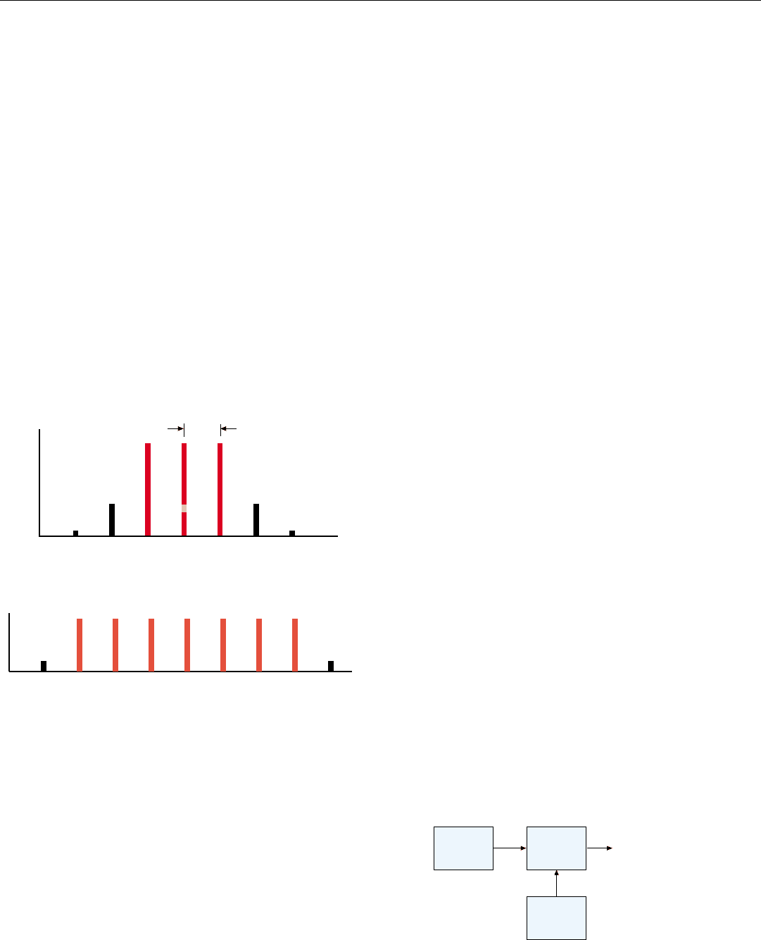
At a low value of the index, a pure sine-wave modulating
signal produces two sidebands having the same amplitude
as the carrier (Fig. 1); with the carrier, they contain 90% of
the output power.
By increasing the modulation index and including har-
monics of appropriate amplitude and phase in the modulat-
ing signal, the number of equal-amplitude sidebands may
be increased and the power in the outer sidebands reduced
to a negligible percentage (Fig. 2).
In this way, SIMFAR produces a constant-amplitude
transmitter-drive signal composed of any desired odd num-
ber
1
of equally spaced, equal-power spectral lines from a
single stable microwave source and a single stable offset-fre-
quency source (Fig. 3).
1. Carrier plus one or more pairs
of sidebands.
1. Spectrum of a phase-modulated carrier. When the modulation
index is low, the carrier and two equal–amplitude sidebands
contain 90% of the output power.
Frequency
f
mod
Amplitude
Carrier
2. By increasing the modulation index and including harmonics
in the modulating signal, the number of equal-amplitude side-
bands may be increased.
Microwave
Source
Phase
Modulator
Offset
Frequency
Source
f
c
f
mod
Constant-Amplitude
Multifrequency
Drive Signal
3. SIMFAR system. From a single stable microwave source and
a single stable offset-frequency source, a constant–amplitude
multifrequency transmitter drive signal is produced.
