George W. Stimson introduction to Airborne Radar (Se)
Подождите немного. Документ загружается.

coordinates by a fast-acting closed-loop servo system incor-
porating rate-integrating gyros on the antenna. If the anten-
na and gimbals are dynamically balanced, this system effec-
tively isolates the antenna from changes in aircraft attitude.
The only beam steering required is that for tracing a search
scan pattern or tracking a target—neither of which necessi-
tate particularly high angular rates.
With an ESA, stabilization is not so simple. Since the
array is fixed to the airframe, every change in aircraft atti-
tude—be it in roll, pitch, or yaw—must be inertially
sensed. Phase commands for steering out the change must
be computed for each radiator, and these commands must
be transmitted to the antenna’s phase shifters or T/R mod-
ules and executed. The entire process must be repeated at a
high enough rate to keep up with the changes in aircraft
attitude.
If the aircraft’s maneuvers are at all severe, this rate may
be exceptionally high. For a nominal “resteer” rate of 2,000
beam positions per second, the phase commands for two to
three thousand radiating elements must be calculated, dis-
tributed, and executed in less than 500 microseconds!
Fortunately, with advanced airborne digital processing
systems, throughputs of this order can be provided.
Summary
Mounted in a fixed position on the aircraft structure, the
ESA produces a beam which is steered by individually con-
trolling the phase of the signals transmitted and received by
each radiating element.
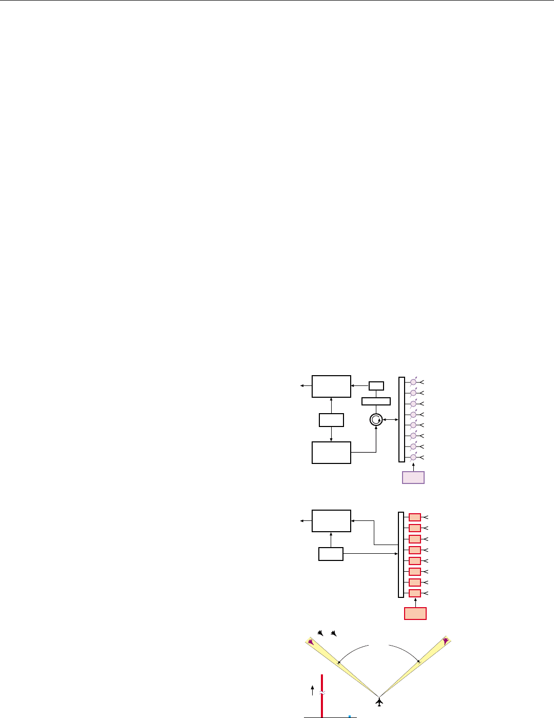
A passive ESA operates with a conventional central trans-
mitter and receiver; while an active ESA has the transmitter
and the receiver front end functions distributed within it at
the radiator level. The passive ESA is considerably more
complex than a mechanically steered array (MSA); the
active ESA is an order of magnitude more complex than the
passive ESA.
Both types have three prime advantages: (1) the contri-
bution of their reflectivity to the aircraft’s RCS in the threat
window of interest can readily be reduced; (2) their beams
are extremely agile; (3) they are highly reliable and capable
of graceful degradation. The active ESA also has the advan-
tages of providing an extremely low receiver noise figure,
affording beam-shaping versatility, and enabling radiation
of independent multiple beams of different frequencies.
The principal limitations of the ESAs are (a) restriction of
the maximum field of regard to roughly ±60° by the fore-
shortening of the aperture and consequent reduction in
gain at large angles off broadside and (b) the requirement
for a substantial amount of processor throughput to stabi-
lize the pointing of the antenna beam in the face of severe
aircraft maneuvers.
CHAPTER 37 Electronically Steered Array Antennas (ESAs)
479
φ
φ
φ
φ
φ
φ
φ
φ
PASSIVE ESA
The beam steering controller (BSC) function
may be performed in the central processor.
Receiver
Exciter
BSC
Duplexer
LNA
Protection
F
E
E
D
Transmitter
ACTIVE ESA
Receiver
Exciter
BSC
T/R
T/R
T/R
T/R
T/R
T/R
T/R
T/R
F
E
E
D
ESAMSA
Time
1 second
< 1 millisecond
100°
481
ESA Design
T
o fully realize the compelling advantages of the
ESA, its design and implementation must meet a
number of stringent requirements, not the least of
which is affordable cost.
This chapter begins by discussing those design consider-
ations common to both passive and active ESAs. It then
takes up the considerations pertaining primarily to passive
ESAs and, finally, those pertaining solely to active ESAs.
Considerations Common to Passive and Active ESAs
The cost of both passive and active ESAs increases
rapidly with the number of phase shifters or T/R modules
required, hence with the number of radiators in the array.
Consequently, a key design requirement common to
both types of ESAs is to space the radiators as widely as
possible without creating grating lobes and—if stealth is
required—without creating Bragg lobes either. The number
of radiators may in some cases be further reduced through
judicious selection of radiator lattice.
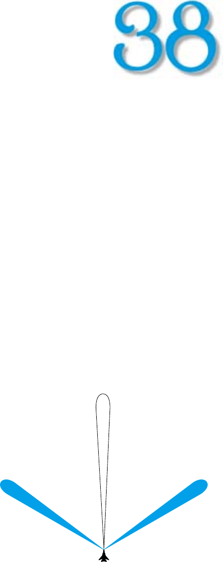
Avoiding Grating Lobes. Grating lobes (Fig. 1) are repe-
titions of an antenna’s mainlobe
1
which are produced if the
spacing of the radiating elements is too large relative to the
operating wavelength. They are undesirable because they
rob power from the mainlobe, radiate this power in spuri-
ous directions, and from these directions receive returns
which are ambiguous with the returns received through the
mainlobe. Also, ground return or jamming received
through the grating lobes may mask targets of interest or
desensitize the radar by driving down the automatically
controlled gain (AGC).
1. And sidelobes, as well.
1. Grating lobes are repetitions of the mainlobe. They are pro-
duced if the spacing of the radiated elements is too large in
comparison to the wavelength.
Main Lobe
Grating Lobe
Grating Lobe
Note: Sidelobes, not
shown, also repeat.
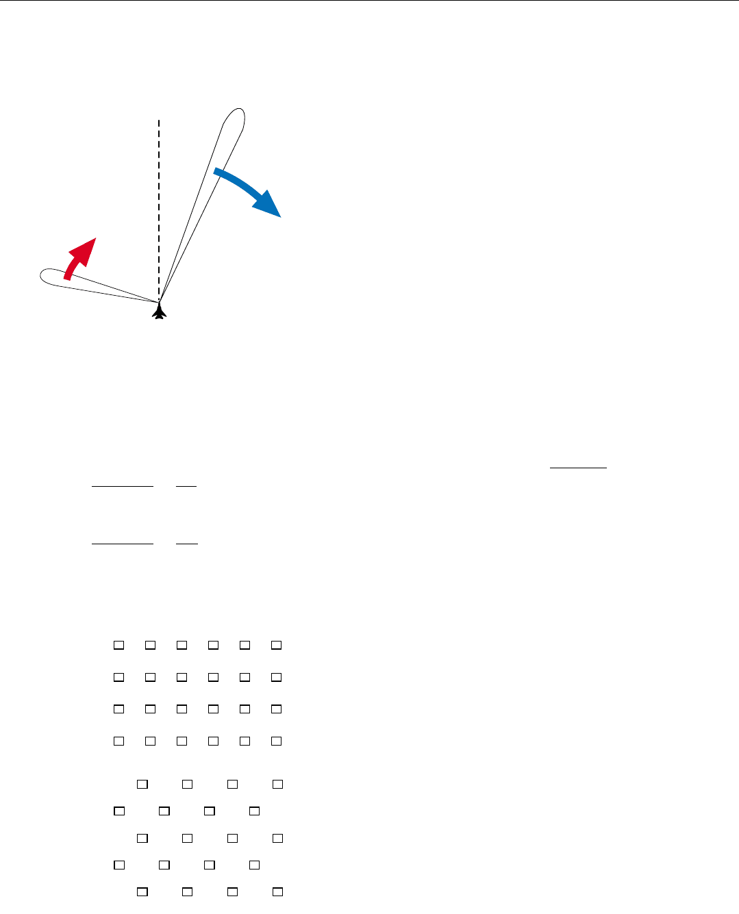
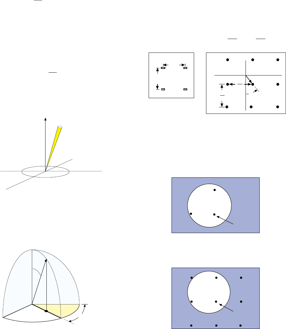
2. With an ESA, if the radiator spacing is not less than 1 wave-
length, as the mainlobe is steered away from broadside, a
grating lobe will appear and move into the field of regard.
PART IX Advanced Concepts
482
Grating lobes are not unique to ESAs. They may be pro-
duced by any array antenna if the radiators are too widely
spaced. Like the mainlobe, they occur in those directions
for which the waves received by a distant observer from all
of the radiators are in phase. As illustrated by the panel on
the facing page, in the case of a mechanically steered array,
where the phases of the waves radiated by all radiators are
the same, grating lobes can be avoided even if the radiators
are separated by as much as a wavelength.
In an ESA, however, the element spacing cannot be this
large. For the angles at which the waves from all radiating
elements are in phase depend not only upon the element
spacing but also upon the incremental element-to-element
phase shift, ∆φ, which is applied for beam steering. As the
mainlobe is steered away from broadside (i.e., as ∆φ is
increased from 0), a grating lobe whose existence was pre-
cluded by the radiators being no more than a wavelength
apart, may materialize on the opposite side of the broadside
direction and move into the field of regard (Fig. 2).
For an ESA, therefore, the greater the desired maximum
look angle, the closer together the radiating elements must
be. The maximum acceptable spacing is
d
max
=
λ
1 + sin
θ
0
where λ is the wavelength and
θ
0
is the maximum desired
look angle. As illustrated in the example (left), for a maxi-
mum look angle to 60°, the maximum radiator spacing is
little more than half the operating wavelength.
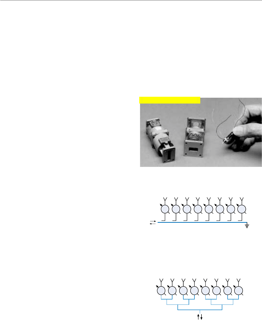
Incidentally, while the possible locations and movement
of grating lobes may be readily visualized for a one-dimen-
sional array, many people find visualizing them for a two-
dimensional array annoyingly difficult. The difficulty may
be avoided, by plotting the lobe positions in so-called Sine
Theta Space, as explained in the panel on page 484.
Avoiding Bragg Lobes. Bragg lobes are retrodirective
reflections
2
which may occur if an array is illuminated by
another radar from certain angles off broadside. If stealth is
required, they must be avoided. As explained in Chap. 39,
avoiding Bragg lobes may require a much tighter radiator
lattice than is necessary to avoid grating lobes.
Choice of Lattice Pattern. For an ESA, the choice of
radiator-lattice pattern may also influence the number of
radiators required.
The most common lattice patterns are rectangular and
triangular or diamond shaped (Fig. 3). With a diamond lat-
tice, the number of radiators may be reduced by up to 14%
without compromising grating lobe performance. The
Main Lobe
Grating
Lobe
Note: Sidelobes, not
shown, also repeat.
Broadside
Direction
If the maximum look angle,
0
, is 30°, what radiator
spacing can be used and still avoid grating lobes?
If
0
is increased to 60°, what must d
max
be reduced to?
d
max
= = = 0.67 λ
λ
1 + sin 30° 1.5
λ
Radiator Spacing Example
d
max
= = = 0.54 λ
λ
1 + sin 60° 1.87
λ
θ
θ
3. Common radiator lattice patterns. With the diamond pattern,
the number of radiators may be reduced by up to 14% with-
out compromising grating lobe performance.
Rectangular
Lattice
Diamond
Lattice
2. Energy reflected back in the
direction from which it came.
CHAPTER 38 ESA Design
483
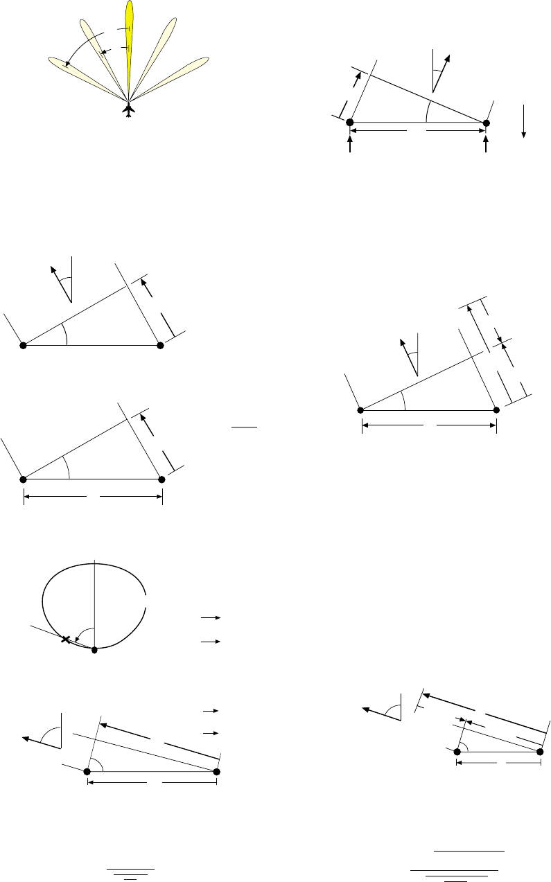
For an ESA, avoiding grating lobes is not quite so
simple. For an incremental phase difference, ∆
φ, is
applied to the excitation of successive radiators to
steer the main lobe to the desired look angle,
L
.
Consequently, for an ESA, grating lobes occur in
those directions,
n
, where the incremental
distance, ∆R
, from successive radiating elements
to a distant observer equals a whole multiple of a
wavelength (nλ) minus the distance, ∆R
φ
,
corresponding to the phase lag, ∆φ.
From this simple relationship,
we can obtain the positions of all possible grating
lobes. Setting n equal to 1 and
L
equal to the
maximum desired look angle,
0
, yields a “worst case”
equation for the position of the first grating lobe.
As with an MSA, to avoid grating lobes the first
grating lobe must be placed at least 90° off
broadside. As illustrated in the diagram below,
1
approaches 90° as d is reduced to λ minus d sin
0
.
So, since sin 90° = 1, letting sin
1
equal 1 and solving
the above equation for d yields the maximum spacing
an ESA's radiators may have and avoid grating lobes.
Where Grating Lobes Occur. Like the main lobe, grat-
ing lobes occur in those directions,
n
,
in which the waves received by a distant observer from
all of the antenna’s radiating elements are in phase.
For an MSA, where all radiating elements are excited in
phase,
n
is simply the direction in which the increment-
tal difference in range, ∆R
, from successive radiating
elements to a distant observer is a whole multiple, n, of
the operating wavelength, λ.
The direction, θ
n
, is thus related to λ and the distance,
d, between radiators by the sine function.
Now, the gain of each radiator goes to zero as
approaches 90°.
And
1
, the direction of the first grating lobe,
approaches 90° as d is reduced to
λ.
So, for an MSA, grating lobes can be avoided by reduc-
ing the spacing of the radiators to 1 wavelength or less.
B
AVOIDING GRATING LOBES
∆R
To Distant
Observer
n
G 0
90°
Gain, G
∆R
= n λ
n = 1, 2, 3, . .
d ≤ λ
∆R
φ
= d sin
d
λ
To Distant
Observer
1
n
∆R
θ
nλ
d
= d sin
n
∆R
φ
= d sin
L
To Distant
Observer
Line of equal
φ
φ
φ –
∆φ
Here, for example, to steer
the beam to the right, the
phase of the excitation for
radiator B is made to lag
that for radiator A by ∆φ.
d
L
∆R
φ
A
1
90°
d
λ
θ
Main
Lobe
1
2
θ
θ
θ
θ
θ
θ
n
θ
θ
θ
θ
θ
θ
1
θ
θ
θ
θ
L
θ
L
θ
θ
θ
θ
n
θ
θ
θ
θ
θ
d sin
1
= λ – d sin
0
θ
θ
θ
θ
θ
(1 + sin
0
)
λ
d ≤
θ
d
1
1
d
sin
0
λ
d sin
1
θ
θ
θ
θ
n λ
d
n
θ
sin
n
=
n λ
d
θ
d sin
n
= nλ – d sin
L
θ
θ
To Distant
Observer
θ
PART IX Advanced Concepts
484
For even a mechanically steered array, visualizing
the possible positions of grating lobes is made difficult
by the fact that their directions,
n
, relative to the antenna
broadside direction are related to the distance, d, between
radiators and the wavelength, λ, by the sine function.
where n is the number of the lobe. (The main lobe is
number 0.)
For an ESA, the difficulty is compounded by
n
being determined not only by the radiator spacing, but
also by the deflection,
0
, of the main lobe from broadside.
In the case of a 2-D ESA, these difficulties are further
compounded by the lobes existing in three-dimensional
space.
An engineer named Von Aulock elegantly solved all
three problems in a single stroke by (a) representing
the main lobe and each grating lobe with a unit vector
(arrow one unit long) and (b) projecting the tip of this
vector onto the plane of the array.
Since the distance from the center of the plane to each
point projected onto it is (1 x sin
n
), Von Aulock named
the plane Sine Theta Space.
SINE THETA SPACE
The beauty of Sine Theta Space is that the position
of the main lobe can be plotted on it simply by scaling
off (in the direction φ relative to the related lattice axis,
u or v) a distance equal to the sine of the lobe's deflection,
0
. The positions of any grating lobes can then be
predicted by scaling off on either side of the main lobe
distances equal to n
λ divided by the radiator spacings
d
u
and d
v
. Thus:
• Main lobe distance = sin
0
(at angle φ)
• Grating lobe distances = ± and ±
Since lobes cannot exist at angles greater than 90°
off broadside, a circle of radius 1 (the sine of 90°) is
drawn around the origin. The area within this circle is
termed “real space”; the area outside it, “imaginary
space.”
When evaluating radiator lattice patterns and radiator
spacing, potential grating lobe positions are often plotted
in imaginary space.
One can then readily see whether any of these lobes
will materialize—i.e., move into real space—when the
main lobe is steered to the limits of the desired field of
regard.
Grating Lobe Diagram
Plotted in Sine Theta Space
Radiator Lattice
φ
sin
0
λ
u
λ
d
u
v
d
u
d
v
d
v
θ
θ
θ
θ
θ
Plane of array
u
position relative to
radiator
–
lattice axis
=
v
θ
φ
Array
Broadside
Main Lobe
u
v
θ
λ
d
u
λ
d
v
Imaginary
Space
Main Lobe
Real Space
Real Space
Main Lobe
sin
n
= n n = 1, 2, 3, . . .
θ
λ
d
sin
n
= n ± sin
0
λ
d
θθ
θ
CHAPTER 38 ESA Design
485
choice of lattice pattern, though, is also influenced by other
considerations, such as RCS-reduction requirements.
The number of radiators may be reduced still further by
selectively thinning the density of elements near the edges
of the array. In assessing thinning schemes, however, their
effects on sidelobes and their interaction with edge treat-
ment for RCS reduction must be carefully considered.
In short, no matter what the scheme, some price is
always paid for reducing the number of radiators beyond
what is achieved by simply limiting their spacing to d
max
.
Design of Passive ESAs
Among basic considerations in the design of passive
ESAs are the selection of phase shifters, the choice of feed
type, and the choice of transmission lines.
Selection of Phase Shifters. In a two-dimensional array
employing 2000 or more radiators, phase shifters (Fig. 4)
typically account for more than half the weight and cost of
the array. Consequently, it is critically important that the
individual devices be light weight and low cost. Also, so as
not to reduce the radiated power and not to increase the
receiver noise figure appreciably, the phase shifters’ inser-
tion loss must be very low. Other critical electrical charac-
teristics of the phase shifters are accuracy of phase control,
switching speed, and voltage standing-wave ratio.
Choice of Feed Type. The feeds used in passive ESAs are
of two basic types: constrained and space. Constrained
feeds may be either traveling-wave or corporate.
In a traveling-wave feed, the individual radiating ele-
ments, or columns of radiating elements, branch off of a
common transmission line (Fig. 5). This type of feed is
comparatively simple. But it has a limited instantaneous
bandwidth. The reason is that the electrical length of the
feed path in wavelengths, hence also the phase shift from
the common source to each radiator is different.
The difference may be compensated by adding a suitable
correction to the setting of the phase shifter for each radia-
tor. But since the required correction is a function of the
wavelength of the signals passing through the feed, any one
phase setting generally provides compensation over only a
narrow band of frequencies.
3
A corporate feed has a pyramidally shaped branching
structure (Fig. 6). It can readily be designed to make the
physical length, hence also the electrical length, of the feed
paths to all radiating elements the same, thereby eliminat-
ing the need for phase compensation. The instantaneous
bandwidth then is limited only by the bandwidths of the
radiators and of the phase shifters, transmission lines, and
connectors making up the feed system.
4. Ferrite phase shifters of the sort used in passives ESAs: X-band
(left); Ku-band (center); Ka-band, removed from its housing
(right).
5. Traveling-wave feed is simple and inexpensive. But, since the
electrical length of the path to each radiator is different, a
phase correction must be made for each element, limiting the
instantaneous bandwidth.
3. Some feeds get around this
limitation but are impractica-
bly bulky.
6. Corporate feed makes the electrical length of paths to all radi-
ators the same, eliminating the need for phase corrections and
widening the instantaneous bandwidth.
Traveling-Wave Feed
φφφφφφφφ
Corporate Feed
φφφφφφφφ
Click for high-quality image
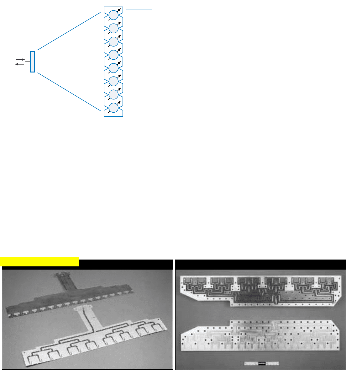
This type of strip line is made of two thin metalized dielectric
sheets. The bottom sheet (foreground) is metalized on both sides.
Metal on top is etched away leaving a strip-like conductor.
The upper sheet is metalized only on top. When the two sheets
are put together, the conductor is sandwiched between the metal
layers and insulated from them by the dielectric.
The result is lightweight, compact, low cost, and can pass
wideband signals. It is lossy, but good for low-power and strong-
signal applications.
Strip-like conductor, etched from the metalized surface of a
dielectric sheet, is sandwiched between thin aluminized sheets into
which matching grooves have been stamped. Supported by the
dielectric, the conductor is separated from the metal by air in the
groves. Also very wide band, it is more expensive than dielectric strip
line but has much lower losses.
In another version of air strip line, conductor is supported at
intervals by plastic standoffs in groves cut into light metal plates by
an automated machine tool.
(RS95-4626)
PART IX Advanced Concepts
486
Space feeds vary widely in design. Figure 7 shows a repre-
sentative feed. In it, a horn or a small primary array of radi-
ating elements illuminates an electronic lens filling the
desired aperture. The lens consists of closely spaced radiat-
ing elements, such as short open-ended wave guide sections,
each containing an electronically controlled phase shifter.
The space feed is simple, lightweight, and inexpensive. It
has low losses and an instantaneous bandwidth comparable
to that of a corporate feed. But the focal length of the pri-
mary array adds considerably to the depth of the antenna.
Also, sidelobe control is difficult to obtain without ampli-
tude tapering at the radiator level.
Choice of Transmission Lines. The transmission lines
commonly used in antenna feed systems are of two general
types: strip line and hollow waveguide.
4
Strip line consists of narrow metal lines (strips) sand-
wiched between metal surfaces. It is lightweight, compact,
and low cost. Moreover, it can pass signals having instanta-
neous bandwidths of up to a full octave! It thus meets the
requirements of applications ranging from ECCM and LPI
to high resolution mapping.
Strip line is of two general types (see panel below). In
one, the strips are insulated from the metal surfaces by a
dielectric sheet, making this feed cheaper but lossy. In the
other—called “power” strip line—losses are minimized by
isolating the strips from the metal surfaces with an air gap.
7.
The space feed is simple, inexpensive and has an instantaneous
bandwidth comparable to a corporate feed’s. But the focal
length of the primary array adds to the depth of the antenna.
4. Strip line is more precisely
defined as transverse electro-
magnetic mode (TEM) trans-
mission line; hollow wave
guide, as transverse electric/
transverse magnetic (TE/TM)
transmission line.
SPACE FEED
Primary
Array
L
e
n
s
φ
φ
φ
φ
φ
φ
φ
φ
REPRESENTATIVE STRIP LINE CONSTRUCTION
Air (Power) Strip Line
Dielectric Strip Line
Click for high-quality image
Hollow metal waveguide (Fig. 8) is heavier, more expen-
sive, and has a limited instantaneous bandwidth. But it has
very low losses. Consequently, it is required for high trans-
mitted powers, weak signal detection, and long runs.
With advances in plastic molding and plating tech-
niques, high-quality low-cost metal-coated hollow plastic
wave guide has become an attractive option.
Design of Active ESAs
The key element of an active ESA is the T/R module.
Among the many important considerations in its design, are
the number of different types of integrated circuit chips
required, the power output to be provided, the limits
imposed on transmitted noise, and the required precision
of phase and amplitude control. Not to be overlooked is the
array’s crucial physical design. Each of these considerations
is discussed briefly below.
Chip Set. Ideally, all of a module’s circuitry would be
integrated on a single wafer. However, because of differ-
ences in the requirements of the various functional ele-
ments, technology for achieving this goal is not presently
available. Consequently, the circuitry is partitioned by func-
tion and placed on more than one chip. The chips are then
interconnected in a hybrid microcircuit (Fig. 9).
CHAPTER 38 ESA Design
487
8. A section of hollow metal waveguide. It is heavier and more
expensive than stripline and has a limited instantaneous band-
width. But, having very low losses, it is required in applica-
tions requiring high transmitter powers and/or weak signal
detection.
9.
Closeup of a representative T/R module (cover removed). Inte-
grated circuit chips are interconnected in a hybrid microcircuit.
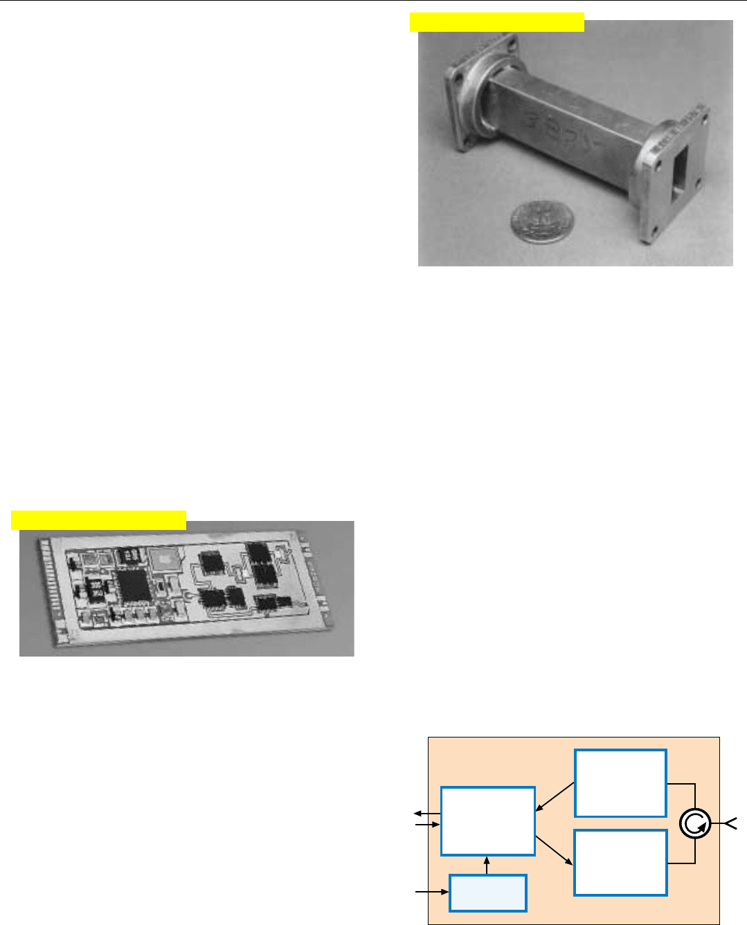
The basic chip set for a T/R module (Fig. 10) includes
three monolithic microwave integrated circuits, called MMICs,
5
plus a digital VLSI (very large scale integrated circuit):
• High-power amplifier (MMIC)
• LNA plus protection circuit (MMIC)
• Variable-gain amplifier and variable phase shifter
(MMIC)
• Digital control circuit (VLSI)
Depending upon the application, to these may be added
other chips, such as a driver MMIC to amplify the input to
the high-power amplifier when high peak powers are
required, circuitry for built-in testing, and so on.
5. Circuits for millimeter wave-
lengths are called MIMICs.
10. Basic chip set for a representative T/R module. Set consists of
three monolithic microwave integrated circuits (MMICs) and
one digital very large
-
scale integrated circuit (VLSI).
Control
(VLSI)
Hybrid Microcircuit
LNA
+
Protection
Circuit
(MMIC)
High-power
Amplifier
(MMIC)
Variable Gain
Amplifier
+
Phase Shifter
(MMIC)
Click for high-quality image
Click for high-quality image
PART IX Advanced Concepts
488
To date, virtually all MMICs for X-band and higher fre-
quencies have been made of gallium arsenide (GaAs), since
it is the only material yet proven capable of handling such
high frequencies. One limitation of GaAs is its very low
thermal conductivity. For the circuitry on a chip to be ade-
quately cooled, the chip must either be ground very thin—
making it fragile and difficult to handle—or mounted on
the hybrid substrate face down (flip-chip technique).
Power Output. In general, for a given array size, the
array’s average power output is dictated by the desired max-
imum detection range. The realizable average power out-
put, however, is usually constrained by (a) the amounts of
primary electrical power and cooling the aircraft designer
allocates to the ESA and (b) the module’s efficiency. For a
given primary power and cooling capacity, the higher the
efficiency, the higher the average power can be.
Regarding module efficiencies, two terms which often
come up are “power added efficiency” and “power over-
head.” These are explained in the panel on the facing page.
In designing the module’s high-power amplifier, the
required peak power is of greatest concern. It, of course,
equals the desired average power per module divided by
the minimum anticipated duty factor.
For a given peak power output from the array as a
whole, the peak power per module is inversely proportional
to the number of modules, hence to the area of the array.
Consequently, to obtain the same peak power from an array
having an area of 4 square feet, as from an array having an
area of 8 square feet, the peak power of each module must
be doubled (Fig. 11).
Transmitter Noise Limitations. As with a radar employ-
ing a central transmitter, noise modulation of the transmit-
ted signal must be minimized. The principal sources of noise
modulation in an active ESA are ripple in the dc input volt-
age and fluctuations in the input voltage due to the pulsed
nature of the load. Because the voltages are low and the cur-
rents are high, adequately filtering the input power is a
demanding task. It may require distributing the power con-
ditioning function at an intermediate level within the array,
or even including a voltage regulator in every T/R module.
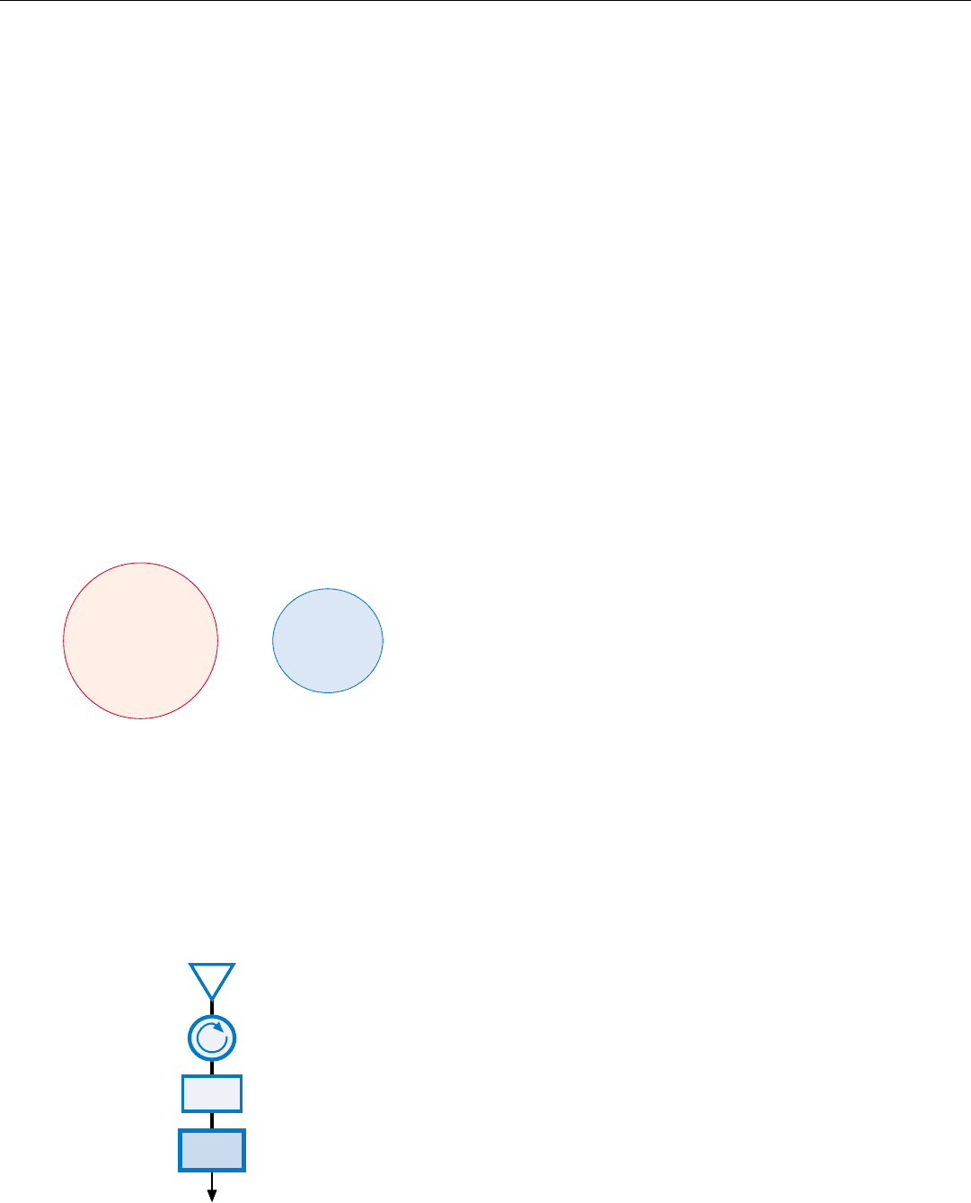
Receiver Noise Figure. Since one of the main reasons for
going to an active ESA is reduction of receive losses, to fully
realize the ESA’s potential it is essential that the T/R module
have an extremely low receiver noise figure. Typically, the
receiver noise figure is quoted for the module as a whole. It
equals the noise figure of the LNA plus the losses ahead of
the LNA—i.e., losses in the radiator, the duplexer, the pro-
tection circuit, and the interconnections (Fig. 12).
12. Receiver noise figure equals the noise figure for the LNA plus
the losses in the elements ahead of the LNA: radiator, duplex-
er, receiver protection circuit, and interconnections.
Duplexer
Receiver
Protection
Radiator
LNA
11. Relationship between the peak power per module and the
area of an array.
For the same peak power output:
8 sq. ft.
Required Peak Power
Per Module = P
4 sq. ft.
Required Peak Power
Per Module = 2P
Phase and Amplitude Control. The precision with which
the phase and amplitude of the transmitted and received
signals must be controlled at the radiator level is dictated
by the maximum acceptable peak sidelobe level of the full
array. The lower it is, the
• Smaller the quantization step sizes of the phase and
amplitude control circuits must be
• Wider the amplitude-control range needed to achieve
the necessary radiation taper across the array for side
lobe reduction
• Smaller the acceptable phase and amplitude errors
Array Physical Design. The performance and cost of an
active ESA depend critically not only upon the design of
the T/R modules, but also upon the physical design of the
assembled array.
In general, the radiators must be precisely positioned
and solidly mounted on a rigid back plane. This is essential
if the antenna’s RCS is to be minimized; for any irregulari-
ties in the face of the array will result in random scattering
which cannot otherwise be reduced (see page 495).
The modules are typically mounted behind the back plane
on cold plates, which carry away the heat they generate.
Behind the cold plates then are: (a) a low-loss feed mani-
fold connecting each module to the exciter and the central
receiver; (b) distribution networks providing control signals
and dc power to each module; and (c) a distribution system
for the coolant that flows through the cold plates.
Just how this general design is implemented may vary
widely. One approach, called stick architecture, is illustrated
in Figs. 13 and 14.
CHAPTER 38 ESA Design
489
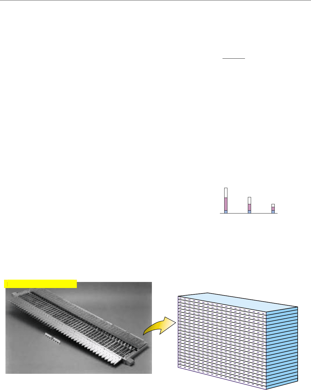
13. A single “stick” for an active ESA of stick-architecture design.
A row of precisely positioned radiators is solidly mounted on a
rigid structure serving as: (a) back plane for the radiators, (b)
cold plate and housing for the T/R modules, and (c) housing
for RF feed, power, and control-signal distribution network.
14. Sticks are rigidly mounted on top of each other to form the
complete array.
Power-Added Efficiency. Since a module’s high-
power amplifier (HPA) typically includes more than
one stage, the efficiency of the final stage is generally
expressed as power added efficiency, E
PA
.
where
P
o
= RF output power
P
i
= RF input power
P
dc
= DC input power.
If the gain of the final stage is reasonably high, the
power added efficiency very nearly represents the
efficiency of the entire amplifier chain.
Power Overhead. This is the power consumed by
the other elements of the module—switching circuitry,
LNA, and module control circuit. Because of this
overhead, a module’s efficiency may be considerably
less than the HPA’s efficiency, which typically is
somewhere between 35 and 45%.
Since much of the overhead power is consumed
continuously, while the RF output is pulsed, module
efficiency may vary appreciably with PRF.
Also, since overhead power is independent of
output power, if all modules are identical, as they
reasonably would be, aperture weighting can
significantly reduce the efficiency of many modules.
To minimize this reduction yet achieve extremely low
sidelobes, special weighting algorithms have been
developed for active ESAs.
MEASURES OF MODULE EFFICIENCY
Aperture
Weighted
PRF 1 PRF 2
Output Power
Loss In HPA
Overhead Power
E
PA
=
P
o
– P
i
P
dc
Click for high-quality image
