Gebali F. Analysis Of Computer And Communication Networks
Подождите немного. Документ загружается.

582 16 Examples of Switches
16.2.4 Promina 4000 Features
In summary, the main features of the Promina 4000 switch are the following:
1. The switch is equipped with a per-VC accounting capability to meet goals of
fairness, QoS guarantees, and efficient buffer use.
2. The switch fabric is based on a contentionless broadcast matrix.
3. An output buffer is employed with adaptive packet discard scheme on a per-VC
basis.
4. The switch can support more than one service class for each of the standard ATM
Forum service classes (CBR, rt-VBR, nrt-VBR, ABR, and UBR).
16.3 The VRQ Switch
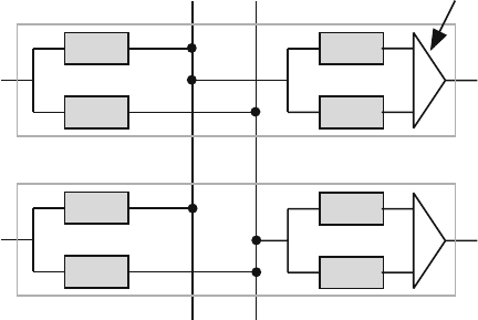
A block diagram of the virtual routing, virtual queuing (VRQ) switch is shown in
Fig. 16.2 [3–5]. The VRQ switch has buffers at both the input and output modules.
However, the switch could be classified as an output queue switch since all decisions
about packet transmission and scheduling are carried out at the output ports. This
is one of the main requirements of a high-performance switch. The switch fabric
is contention-free (contentionless) and is based on a broadcast matrix of dedicated
backplane buses.
An N × N VRQ switch is composed of N stacked modules where each module
contains an input port and an output port, as shown. The modules are connected
together using N backplane buses. Each bus is dedicated to an output port but can
take its data from any input port. The reader can immediately see that contention
1
N
Dedicated
input buffers
1
N
1
K
1
K
Module 1
1 N
Module N
Virtual
output queues
Dedicated
backplane buses
...
...
...
...
...
...
...
Output
selectors
Fig. 16.2 The virtual routing, virtual queuing (VRQ) high-performance switch
16.3 The VRQ Switch 583
could potentially occur when two or more inputs want to access a certain output.
This is prevented here since the bus is output driven, not input driven, in the sense
that each output dictates which input is to access the bus. This choice is based on
the scheduling algorithm employed at each output port.
16.3.1 Input Port Operation
The input port contains N buffers and each buffer is dedicated to an output port.
This in itself presents certain advantages and disadvantages. The main advantage is
that a buffer has to perform only one read/write operation per time step, irrespective
of the switch size.
Clever memory design ensures that each input buffer has a cycle time that is the
least possible through elimination of memory address decoders and bit line drivers.
This design ensures that buffer speed will present no bottleneck to switch perfor-
mance.
When a packet arrives, the input port controller routes it to one of the input buffer
in the module, based on the header information. The input controller also informs
the destination output port that a packet has arrived and also provides to the output
an address,orapointer, indicating where this packet is located in the input buffer.
Thus packet routing has been virtually accomplished through this pointer exchange,
hence the name virtual routing. The packet will actually get routed out of the switch
when the output port selects it based on its scheduling algorithm.
16.3.2 Backplane Bus Operation
Each bus is dedicated to an output port and could be driven by any input port, as
shown in the figure. The output port controls access to the bus, and we say that the
bus is output driven. Thus, only one packet moves across the bus per time step and
the bus speed matches the line speed without the need to use any speedup factor or
multiplexing schemes, such as TDMA. Again, bus speed will present no bottleneck
to switch performance. In effect, the switch fabric is contentionless since it is based
on a matrix of dedicated buses that are output driven.
16.3.3 Output Port Operation
The output port contains K queues. The queues store the packet pointers and not the
actual packets, hence the name virtual queuing. The queues could be constructed
based on a per-connection basis, per-input basis, or per-service class basis. In either
case, the size of these queues is minimal since they do not store actual packets.
They only store pointer to the packets. This gives the designer much freedom in
configuring the queues based on actual traffic requirements.
584 16 Examples of Switches
16.3.4 VRQ Features
In summary, the main features of the VRQ switch are as follows:
1. Fast input buffers: Each input module of the switch contains input buffers to store
incoming packets. Those buffers are shift register based, as opposed to RAM
based. The use of shift registers dramatically increases buffer speed due to re-
moval of address decoding circuitry, word and bit line drivers, and sense ampli-
fier delays. A shift register acts in effect as a pipelined memory with operation
speed dictated only by the speed of moving data between adjacent flip-flops.
Thus, memory delay is the sum of setup and delay times of one-bit flip-flop.
This is a much higher memory speed compared to a standard memory where the
delay time is determined by the sum of delays of the address decoder, word line,
bit line, and sense amplifier.
2. Distributed routing: The routing operation is localized in each input port.
3. Distributed scheduling algorithm: Packet selection among the different output
queues is localized in each output port. The small size of output queues enables
supporting several scheduling algorithms.
4. Contentionless switch fabric: The switching fabric is output driven which pre-
vents any contention and its operating speed matches the line rate.
5. Modularity: The switch is very modular at the input ports, output ports, and at
the backplane switch matrix itself.
6. Local communication: The input and output modules need not communicate any
state information. This removes the need for global communication between the
input ports.
7. Point-to-point bussing: The backplane buses between each output port and as-
sociated buffers at the inputs can be implemented by point-to-point optical fiber
lines. This results in fast operation and ability to directly drive output optical
fiber links.
8. Low packet loss probability: Packets can only be lost due to filled input buffers
because internal and output blocking are eliminated.
16.4 Comparing Promina 4000 with VRQ Switch
As a final note, we can compare the two switches since superficially both seem
to possess very similar structures. The main differences between the two switches
are:
1. In the VRQ switch, each backplane bus is dedicated to an output port. In the
Promina 4000 switch, each backplane bus is dedicated to an input port.
2. The buses in the VRQ switch are output driven to prevent contention and colli-
sions. Thus, contention is removed in the VRQ switch without having to resort
to time multiplexing, as in the Promina 4000 switch. The buses in the Promina
switch are input driven and contention, or collision, is avoided by using TDMA
16.5 Modeling the VRQ Switch 585
multiplexing. This implies high bus speed which could prove to be a bottleneck
for higher line rates.
3. The backplane bus speed in the VRQ switch exactly matches the line rate (e.g.,
155 Mbps), while the bus speed in the Promina 4000 switch is four times the
input line rate. This might prove to be a bottleneck if higher line rates are contem-
plated unless space division switching (SDM), instead of TDMA, is employed.
Of course, this will only increase the area, power, and pin count of the system.
4. The buffer location is different in the two switches. In the VRQ switch, pack-
ets are stored in input buffers. In one time step, only one read/write operation
is required as a maximum. This relaxes to a great extent the requirements on
memory cycle time. In the Promina 4000 switch, the buffer is located at each
output port. In one time step, a maximum of N write and one read operations
are required. This naturally is a severe restraint on the memory cycle time. The
option, of course, is not to share the buffer among all the connections or ser-
vice classes but to partition the memory so that the number of access requests
is reduced.
5. Buffer partitioning is also different in the two switches. In the VRQ switch,
a two-level partitioning scheme is employed. First, the buffers are distributed
among the input ports. Second, the buffers in each input port are further parti-
tioned such that each local partition stores packets destined to a particular out-
put port. In the 4000 switch, a one-level partitioning scheme is employed. The
buffers are distributed among the output ports. In one time step, a maximum of N
write and one read operations are required. This naturally is a severe restraint on
the memory cycle time. The option of course is not to share the buffer among all
the connections or service classes but to partition the memory so that the number
of access requests is reduced.
6. Traffic flow in the VRQ switch is output driven which eliminates contention
altogether. In the Promina 4000 switch, traffic flow is input driven which nor-
mally gives rise to contention. This is avoided by use of time-division multiplex-
ing and dedicated backplane buses dedicated to each input port.
16.5 Modeling the VRQ Switch
We provide in this section a simple queuing model for the VRQ switch to illustrate
its performance and to provide more examples of applying queuing theory to another
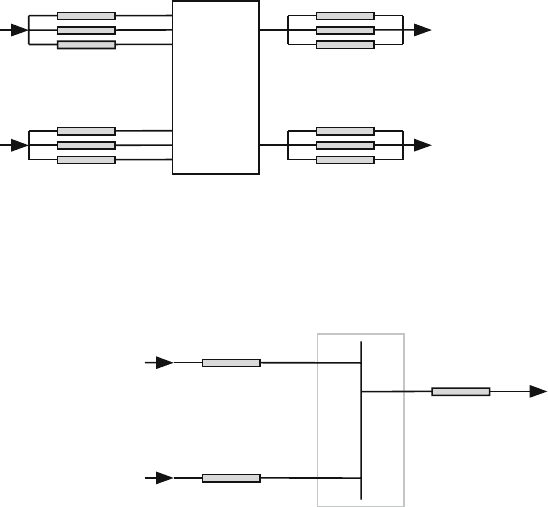
switch architecture. Figure 16.3 is a simplified version of the VRQ switch. The
diagram shows a VRQ switch with N input ports and each input port has N buffers
for storing the packets destined to the N output ports. Each output port has N virtual
queues such that there is one virtual output queue dedicated to each input port. Let
us look at a particular tagged output port. That port will have associated with it N
input buffers in each of the N input ports as shown in Fig. 16.4. The figure shows
the backplane bus connecting all the input buffers in each input to the output virtual
queue at the tagged output port.
586 16 Examples of Switches
Backplane
Bus
Matrix
Input
Buffers
N
1
...
1: N
1: N
Output
Virtual
Queues
N
1
...
1: N
1: N
Fig. 16.3 A simple implementation of the virtual routing, virtual queuing (VRQ) high-
performance switch
Fig. 16.4 The input buffers
associated with a particular
output port
Input Buffers
Associated with
Tagged Output
N
1
...
Tagged
Output
We make the following assumptions for our analysis.
1. There are N buffers at each input port.
2. Each input buffer has one input and one output.
3. The size of each input buffer is B
1
.
4. a is the packet arrival probability at any input of the switch.
5. An arriving packet is served at the same time step at which it arrives.
6. Each arriving packet has equal probability 1/N of requesting an output port.
7. There is only one service class supported by the switch. Support of different
service classes requires more elaborate modeling or can be done accurately
only using numerical techniques.
8. There are N queues at each output port such that each output queue is dedicated
to a particular input port.
9. Each output queue has N inputs and one output.
10. The size of each output queue is B
2
.
11. When a packet arrives at an input port, the corresponding output queue is also
updated.
12. When a packet leaves an output port, the corresponding input buffer is also
updated.
13. Data broadcast or multicast are not implemented.

16.5 Modeling the VRQ Switch 587
14. Packet loss occurs only in the input buffers.
15. The backplane bus is contentionless.
Based on the above assumptions, we model the input buffer in each input port
as an M/M/1/B queue and we model each output queue as an M/M/1/B queue.
Furthermore, each input buffer has an identical output queue and the buffer size for
both queues are equal and is given by
B
1
= B
2
= B
16.5.1 Analysis of the Input Buffer
Queuing analysis of the buffers at each input port is very similar to the analysis used
for the input buffer switch discussed in Chapter 15. The assumptions imply that the
input buffer can be treated as M/M/1/B queue since only one packet can arrive per
time step and only one packet can depart. The arrival probability at an input buffer
is given simply by
a
1
=
a
N
(16.2)
and the departure probability from an input buffer c
1
is given by
c
1
= c
2
(16.3)
where c
2
is the departure probability from an output queue. This equation shows
that there is close and unavoidable coupling between the input and output queues in
the VRQ switch.
The transition matrix for the input buffer is of dimension (B +1) ×(B +1) and
is given by
P
1
=
⎡
⎢
⎢
⎢
⎢
⎢
⎢
⎢
⎢
⎢
⎢
⎢
⎢
⎢
⎣
1 −a
1
d
1
b
1
c
1
0 ··· 00 0
a
1
d
1
fb
1
c
1
··· 00 0
0 a
1
d
1
f ··· 00 0
00a
1
d
1
··· 00 0
.
.
.
.
.
.
.
.
.
.
.
.
.
.
.
.
.
.
.
.
.
000··· b
1
c
1
00
000··· fb
1
c
1
0
000··· a
1
d
1
fb
1
c
1
000··· 0 a
1
d
1
1 −b
1
c
1
⎤
⎥
⎥
⎥
⎥
⎥
⎥
⎥
⎥
⎥
⎥
⎥
⎥
⎥
⎦
(16.4)

588 16 Examples of Switches
where
b
1
= 1 −a
1
d
1
= 1 −c
1
f = a
1
c
1
+b
1
d
1
The throughput or output traffic for the input buffer is given by
Th
1
= N
a,1
(out)
= a
1
c
1
s
0
+
B
i=1
c
1
s
i
packets/time step (16.5)
where s
i
is the probability that the queue has i packets. The first term on the RHS
is the probability that a packet arrives while the queue is empty and the second term
on the RHS is the probability that the queue has packets to transmit. Simplifying,
we get
Th
1
= c
1
×
(
1 −b
1
s
0
)
packets/time step (16.6)
The throughput in units of packets/s is
Th
1
=
Th
1
T
packets/s (16.7)
where T is the time step value.
To find the efficiency of the input buffer, we must estimate the input traffic in
units of packets per time step. The input traffic is given by
N
a
(in) = 1 ×a
1
+0 ×b
1
= a
1
=
a
N
packets/time step (16.8)
The efficiency of the input buffer is defined as the ratio between output traffic
and input traffic
η
1
=
Th
1
N
a
(in)
=
c
1
(
1 −b
1
s
0
)
a
1
(16.9)
16.5 Modeling the VRQ Switch 589
The average lost traffic in the input buffer is given by
N
a,1
(lost) = N
a
(in) − N
a,1
(out)
= a
1
−c
1
(
1 −b
1
s
0
)
packets/time step (16.10)
The packet loss probability at the input buffer is given by
L
1
= 1 −η
1
= 1 −
c
1
(
1 −b
1
s
0
)
a
1
(16.11)
The average queue size is given by the equation
Q
1
=
B
i=0
is
i
packets (16.12)
where s
i
is the probability that there are i packets in the input queue.
Using Little’s result, the input buffer delay is given by
Q
1
= W
1
Th
1
packets (16.13)
or
W
1
=
Q
1
Th
1
time steps (16.14)
The delay in seconds is given by
W
1
= W
1
T seconds (16.15)
16.5.2 Analysis of the Output Queue
The VRQ dedicates at least one output queue for each output port. The output
scheduler selects a packet from one of the queues for service based on any of the
scheduling techniques discussed in Chapter 12.
For the case when the VRQ supports differentiated services with K classes, each
output port would dedicate K queues for each input port. Thus, each output port
would have a total of KN queues. The output scheduler selects a packet from one
of the queues for service based on any of the scheduling techniques discussed in
Chapter 12. However, we assume that K = 1 here for simplicity.
The assumptions we used for the VRQ switch imply that the output queues are
M/M/1/B type. The VRQ works on the principle that an arriving packet at an
input port updates the contents of the virtual queue of its destination output port.
590 16 Examples of Switches
Therefore, the arrival probability at the input of a tagged output queue is given by
a
2
= a
1
=
a
N
(16.16)
The departure probability of the output queue is really simple
c
2
= c
1
=
1
N
(16.17)
We conclude, therefore, that the output queue dedicated to an input port behaves
exactly like the input buffer we studied in the previous section.
We can write
Th
2
= Th
1
=
1
N
×
(
1 −b
1
s
0
)
packets/time step (16.18)
η
2
= η
1
=
1 −b
1
s
0
a
(16.19)
N
a,2
(lost) = N
a,1
(lost)
=
1
N
×
(
a − 1 +b
1
s
0
)
packets/time step (16.20)
L
2
= L
1
= 1 −
1 −b
1
s
0
a
(16.21)
W
2
= W
1
=
Q
1
Th
1
time steps (16.22)
16.5.3 Putting It All Together
The throughput of the switch per output port equals the throughput of the output
queue
Th = Th
1
=
1
N
×
(
1 −b
1
s
0
)
packets/time step (16.23)
The lost traffic for the switch is given by
N
a
(lost) = N
a,1
(lost)
=
1
N
×
(
a − 1 +b
1
s
0
)
packets/time step (16.24)
16.5 Modeling the VRQ Switch 591
The total packet loss probability is given by
L = L
1
= 1 −
1 −b
1
s
0
a
(16.25)
and the total delay of packets within the switch is given by
W = W
1
=
Q
1
Th
1
time steps (16.26)
16.5.4 Performance Bounds on VRQ Switch
Under full load conditions (a → 1), the packet arrival probability in (16.2) becomes
a
1
=
1
N
(16.27)
Thus, the packet arrival and departure probabilities from any input buffer become
equal
a
1
= c
1
=
1
N
(16.28)
The M/M/1/B queue distribution index ρ becomes unity
ρ =
a
1
d
1
b
1
c
1
= 1 (16.29)
Thus, the probability of the queue being in state i is given from the M/M/1/B
queue results in 7.17 on page 230 by
s
i
=
1
B
0 ≤ i ≤ B (16.30)
The throughput in (16.18) under full load conditions will become
Th(max) =
1
N
×
1 −
1
B
1 −
1
N
packets/time step (16.31)